
Related Manuals for horiba LAQUA-PC1100


Summary of Contents for horiba LAQUA-PC1100
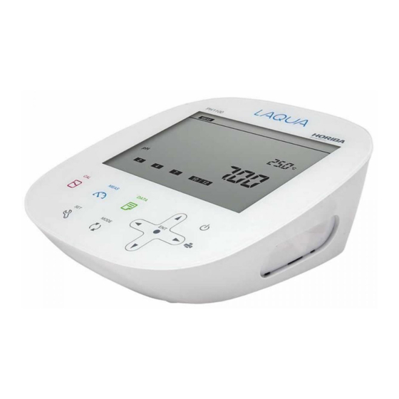
- Page 1 Benchtop pH/ORP/Conductivity Meter LAQUA-PC1100 Instruction Manual CODE:GZ0000427795...
- Page 3 HORIBA, Ltd. warrants that the Product shall be free from defects in material and workmanship and agrees to repair or replace free of charge, at option of HORIBA, Ltd., any malfunctioned or damaged Product attributable to responsibility of HORIBA, Ltd. for a period of two (2) years from the delivery unless otherwise agreed with a written agreement.
- Page 4 Check items Items in package ■ After opening the package, check for damage on the instrument and that the standard accessories (see below) all exist. If damage or defects are found on the product, contact your dealer. Instrument Instruction manual (this book) USA Europe U.K.
- Page 5 Regulations ■ EU regulations ●Conformable standards This equipment conforms to the following standards: EMC: EN61326-1 Class B, Basic electromagnetic environment Safety: EN61010-1 RoHS: EN50581 9. Monitoring and control instruments Warning: This product is not intended for use in industrial environments. In an industrial environment, electromagnetic environmental effects may cause the incorrect performance of the product in which case the user may be required to take adequate measures.
- Page 6 Regulations ■ FCC rules Any changes or modifications not expressly approved by the party responsible for compliance shall void the user's authority to operate the equipment. ●WARNING This equipment has been tested and found to comply with the limits for a Class A digital device, pursuant to part 15 of the FCC Rules.
-
Page 7: Hazard Classification And Warning Symbols
For your safety Hazard classification and warning symbols ■ Warning messages are described in the following manner. Read the messages and follow the instructions carefully. ●Hazard classification This indicates an imminently hazardous situation which, if not avoided, will result in death or serious injury. This is to be limited to the most extreme situations. -
Page 8: Safety Precautions
For your safety Safety precautions ■ This section provides precautions for using the product safely and correctly and to prevent injury and damage. The terms of DANGER, WARNING, and CAUTION indicate the degree of imminency and hazardous situation. Read the precautions carefully as it contains important safety messages. -
Page 9: Product Handling Information
For your safety Product handling information ■ ●Operational precautions (instrument) ・Only use the product including accessories for their intended purpose. ・Do not drop, crash, or give any physical impact on the instrument. ・Do not immerse the instrument into alcohol, organic solvent, strong acid, strong alkaline, or the like. - Page 10 For your safety ●Disposal ・Standard solution used for the calibration must be under neutralized before the disposal. ・When disposing of the product, follow the related laws and/or regulations of your country for disposal of the product. VIII...
-
Page 11: Description In This Manual
Manual information Description in this manual ■ Note This interprets the necessary points for correct operation and notifies the important points for handling the product. Reference This indicates the part where to refer for information. This indicates reference information. -
Page 12: Table Of Contents
Contents Preface ................... I ■ Items in package..............II ■ Hazard classification and warning symbols ....V ■ Safety precautions............. VI ■ Product handling information ......... VII ■ Description in this manual..........IX Part names and basic operation......... 1 ■ Names of each part..............2 ●... - Page 13 Contents ● Saving measured values ............30 ● Printing measured values in the measurement mode...30 ■ mV, ORP measurement.............31 ● Switching between absolute value and relative value...31 ● Performing measurement............32 ● Saving measured values ............33 ● Printing measured values in the measurement mode...33 ■...
- Page 14 Contents ● Resetting to factory default settings ........65 ● Setting the date and time ............66 ● Performing test printing of the printer unit ......68 ● Setting automatic print............. 69 ● Setting password..............70 ■ Other settings ..............71 ●...
- Page 15 Contents ■ Troubleshooting ..............89 ● The indicated value fluctuates..........89 ● The response is slow..............90 ● The indicated value does not change/No response ....90 ● The measured value is outside the display range ....90 ● Repeatability of the measured value is poor......91 ●...
-
Page 17: Part Names And Basic Operation
Part names and basic operation This section describes the name of each part and the main role, function, and basic operation method of each part. ■ Names of each part..............2 ● Instrument....................2 ● Display....................4 ● Operation key ..................5 ■... -
Page 18: Names Of Each Part
Names of each part Names of each part ■ ● Instrument Display Electrode stand Operation key CH1 reference electrode (R) jack CH2 measurement electrode (G) CH1 measurement electrode (G) connector connector CH2 temperature electrode (T) jack CH1 temperature electrode (T) jack CH1: For pH or ORP measurement CH2: For Conductivity measurement Printer or RS-232C connector... - Page 19 Names of each part • Identification of manufacturing date Manufacturing date can be identified from MFG No. described in the ID label on the backside of the instrument. Third number from the left in the MFG No. indicates manufacturing year. Forth alphabet from the left in the MFG No.
-
Page 20: Display
Names of each part ● Display Electrode status icon Printer connecting icon Data memory icon Status icon Error No., USB icon Data No., Date Temperature Active mode Measurement Measurement unit parameters Calibration points HOLD indicator... -
Page 21: Operation Key
Names of each part ● Operation key This instrument employs capacitance switches. You can not operate them with thick gloves. Operate them with bare hands or thin rubber gloves. Name Function Enters the calibration mode. CAL key Performs the calibration. Enters the measurement mode. -
Page 22: Basic Operation
Basic operation Basic operation ■ ● Function layer The function layer of the data mode and setting mode is shown as below. "dX" and "PXX" indicates the program number which is shown in the screen of the instrument. • Data mode Screen Layer Description... - Page 23 Basic operation • Setting mode < Channel 1 > Screen Layer Description P1: PH pH measurement settings P11: RESOL Selection of resolution: 0.1, 0.01, 0.001 P12: BUFFER Selection of standard solution type for calibration: USA, NIST, CUST P13: CAL.DAT Calibration data display P14: CAL.ALR Calibration alarm setting: 1 day to 400 days...
- Page 24 Basic operation < Channel 2 > Screen Layer Description P1: COND Conductivity measurement settings P11: CELL Cell constant setting P12: UNIT Selection of unit: S/cm, S/m, mS/cm FIX P13: CAL.DAT Calibration data display P14: AT. CAL Selection of auto calibration, manual calibration P15: CAL.CLR Deletion of calibration data...
-
Page 25: Changing The Operation Mode
Basic operation ● Changing the operation mode Change the operation mode from four available modes depending on the purpose of use. The status icon indicates the current mode. You can change the operation mode using the corresponding key. However changing to the calibration mode, data mode, or setting mode is possible only from the measurement mode. -
Page 26: Switching The Active Channel
Basic operation ● Switching the active channel Press the keys to switch the active channel between CH1 and CH2. When CH1 is active, "ACT" icon is displayed on the upper part of the screen. When CH2 is active, "ACT" icon is displayed on the lower part of the screen. ●... -
Page 27: Entering Numeric Values
Basic operation ● Entering numeric values When entering numeric values to make various settings and set a calibration value, you can change the selected digit using the keys and increment or decrement the value (0 to 9) using the keys. ●... - Page 28 M E M O...
-
Page 29: Measurement
Measurement This section describes the basic method of measurement of each measurement parameters. ■ Preparation ................. 14 ● Confirmation before starting measurement ........14 ● Turning ON the instrument..............15 ● Connecting an electrode ..............16 ■ pH measurement................ 17 ●... -
Page 30: Preparation
Preparation Preparation ■ ● Confirmation before starting measurement ・ Have you prepared the appropriate electrode for the measurement parameter? ⇒ If not, purchase the appropriate electrode. ・ Is the prepared electrode in good condition? ⇒ If the responsive part is stained or damaged, it may not be possible to obtain ... -
Page 31: Turning On The Instrument
Preparation ● Turning ON the instrument Perform the following procedure to connect AC adapter to the instrument. 1. Insert the AC adapter cable by fitting with the AC adapter jack. 2. Insert the AC adapter into the electrical socket. AC adapter jack 3. -
Page 32: Connecting An Electrode
Preparation ● Connecting an electrode To perform measurement, it is necessary to use the appropriate electrode for measurement parameters. Recommended electrodes for each measured sample are listed in our product catalog and on our website. Refer to them when preparing electrodes. -
Page 33: Ph Measurement
pH measurement pH measurement ■ You can measure the pH of the sample with a combination pH electrode or a single pH electrode. When a single pH electrode is used, the reference electrode is needed and the reference electrode connector has to be inserted into the jack of the CH1 reference electrode (R). pH can be measured using CH1 of the instrument. - Page 34 pH measurement 3. In the case of "MTC", enter the temperature to be compensated for and press key to confirm. Enter a number To return to the measurement mode, press the key.
- Page 35 pH measurement • Setting the standard solution used for calibration (default: USA) Set the standard solution used for calibration. With this instrument, you can choose from three types, USA, NIST, and CUST (the standard solution other than USA and NIST). Set according to the standard solution to be used.
- Page 36 pH measurement 4. Press the keys to select "USA", "NIST", or "CUST" according to the standard solution to be used, and then press the key to confirm selection. Selected "USA" and press the To return to the measurement mode, press the key.
-
Page 37: Performing Calibration
pH measurement ● Performing calibration Calibration is necessary to measure pH accurately. We recommend performing calibration once a day, before the first measurement. According to the following procedure, perform calibration accurately. Note ・ Perform two-point calibration using pH 7 and pH 4 when you know that the sample is acidic;... - Page 38 pH measurement 5. Press the key or key. Calibration to the standard solution value at the measured temperature is performed. The 1st point calibration ends and the "7" calibration history icon lights, indicating that pH 7 calibration is complete. The display returns to the measurement screen. key or Stabilized 6.
- Page 39 pH measurement Two-point calibration is complete. When calibrating three points or more, use the same procedure to continue calibrating the 3rd and subsequent points after the 2nd point calibration. You can calibrate up to five points. Also, you can inspect repeatability using the pH 7 standard solution. About the repeatability inspection procedure, refer to “...
- Page 40 pH measurement • Inspecting repeatability You can inspect repeatability using the pH 7 standard solution by returning to the calibration screen after calibration ends and pressing the key. Measure the pH 7 standard solution by using the calibrated electrode to display the difference between the measured value and standard solution value with absolute value.
- Page 41 pH measurement • pH standard solution setting: CUST This section describes the procedure for two-point calibration. 1. Clean the pH electrode with pure water (or deionized water) and wipe it with filter paper or tissue paper. 2. Open the internal solution filler port of the pH electrode.
- Page 42 pH measurement 5. Enter the standard solution value and press the key or key. Calibration to the set standard solution value is performed. The 1st point calibration ends and the "1" calibration history icon lights, indicating that 1st point calibration is complete.
- Page 43 pH measurement 8. Enter the standard solution value and press the key or key. Calibration to the set standard solution value is performed. The 2nd point calibration ends and the "2" calibration history icon lights, indicating that 2nd point calibration is complete.
- Page 44 pH measurement • Check of the pH electrode status After calibration is complete, the current pH electrode status is diagnosed from the calibration result. Refer to the following table for maintenance of the electrode. Display Description Reference Both Electrode sensitivity: 85% to 100% ERROR No.
-
Page 45: Performing Measurement
pH measurement ● Performing measurement You can perform measurement in the measurement mode by immersing the pH electrode in the sample. You can use the automatic hold function to judge the stability of the measured value. The automatic hold function has two modes, the auto stability mode and the auto hold mode. -
Page 46: Saving Measured Values
pH measurement Note ・ The criteria of stability judgment in the automatic hold measurement are as follows. Potential variation for 10 seconds is less than 1 mV (0.015 pH equivalent) and temperature variation is less than 2.0°C ・ If the measured value is below the display range, "Ur" (under) appears. If the measured value is above the display range, "Or"... -
Page 47: Mv, Orp Measurement
mV, ORP measurement mV, ORP measurement ■ You can measure the electromotive force between the electrode and the sample by using a pH electrode. The mV value can be used to understand the status of the electrode in the mV measurement. You can measure the ORP (oxidation-reduction potential) of the sample by using an ORP electrode in the ORP measurement. -
Page 48: Performing Measurement
mV, ORP measurement ● Performing measurement You can perform measurement in the measurement mode by immersing the pH electrode in the sample. Also, you can use the automatic hold function to judge the stability of the measured value. The automatic hold function has two modes, the auto stability mode and the auto hold mode. -
Page 49: Saving Measured Values
mV, ORP measurement Note ・ The criteria of stability judgment in the automatic hold measurement are as follows. Potential variation for 10 seconds is less than 1 mV and temperature variation is less than 2.0°C ・ If the measured value is below the display range, "Ur" (under) appears. If the measured value is above the display range, "Or"... -
Page 50: Conductivity Measurement
Conductivity measurement Conductivity measurement ■ The conductivity cell can be used to measure the conductivity, salinity, TDS, and resistivity of a sample. Salinity, TDS, and resistivity are calculated from the measured conductivity value. Press the key to select the measurement parameter (refer to “ Changing the measurement parameter ”... -
Page 51: Setting The Instrument
Conductivity measurement ● Setting the instrument • Setting the temperature display When a conductivity cell with a temperature sensor is used, or a conductivity cell without a temperature sensor is used with a temperature electrode, the automatic temperature measurement function can be used. During measurement, the temperature sensor measures the temperature of the sample and displays the result on the instrument. - Page 52 Conductivity measurement • Setting the conductivity unit (default: S/cm) Select the conductivity unit from three options, S/cm, S/m, mS/cm FIX (fixed at mS/cm) depending on your application. When measuring resistivity, these units correspond to Ω·cm, Ω·m, Ω·cm (for mS/cm FIX). 1.
- Page 53 Conductivity measurement 4. Press the keys to select the unit and press the key to confirm selection. (Ex.: "S/cm" is selected) To return to the measurement mode, press the key.
- Page 54 Conductivity measurement • Setting the salinity unit (default: PPT) Select the salinity unit from % or PPT depending on your application. 1. Press the key when to enter the setting mode when "ACT" icon is displayed on the lower part of the screen. 2.
- Page 55 Conductivity measurement • Setting the cell constant (default: 1.000×1.0 cm A cell constant is unique for each conductivity cell. To measure conductivity correctly, the cell constant of the conductivity cell must be set in the instrument. 1. Press the key when to enter the setting mode when "ACT" icon is displayed on the lower part of the screen.
- Page 56 Conductivity measurement 5. Press the keys to enter the number of the cell constant of the conductivity cell and then press the key to confirm. Enter a number To return to the measurement mode, press the key. Note ・The unit used for the cell constant corresponds the unit set in “ Setting the conductivity unit (default: S/cm) ”...
- Page 57 Conductivity measurement • Setting the temperature conversion (Default: ON, 2.00%/°C) The measured value of a sample that is not at 25°C can be converted to a value at the selected temperature. To use the temperature conversion function correctly, temperature coefficient (the rate of change per 1°C of the conductivity) must be set for each sample. The setting of “...
- Page 58 Conductivity measurement • Setting the reference temperature (Default: 25°C) Temperature to be converted can be selected from 15°C to 30°C. 1. Press the key to enter the setting mode when "ACT" icon is displayed on the lower part of the screen. 2.
- Page 59 Conductivity measurement • Setting the TDS method TDS is calculated from the measured conductivity value. The available calibration methods are "Linear": KCl with factor adjustable from 0.40 to 1.00 (default: 0.50), "442": Myron L 442 non-linear standard curve, "En": European environmental standard non- linear curve, and "NaCl": non-linear salinity curve.
- Page 60 Conductivity measurement 4. Press the keys to select the TDS method and then press the key. 5. When selecting "Linear," enter the factor and then press the key to confirm. Selected "Linear" and then press the Enter a number To return to the measurement mode, press the key.
- Page 61 Conductivity measurement • Setting the salinity method Salinity is calculated from the measured conductivity value. The available calibration methods are "NaCl" and "SEA WATER". 1. Press the key to enter the setting mode when "ACT" icon is displayed on the lower part of the screen.
-
Page 62: Performing Conductivity Calibration
Conductivity measurement ● Performing conductivity calibration The factory-certified cell constant is indicated on the label on the electrical conductivity cell. Cell constant may change depending on the usage condition. In such case, the conductivity cell can be calibrate automatically or manually. You can select calibration method. - Page 63 Conductivity measurement • Manual calibration 1. Clean the conductivity cell with pure water (or deionized water) and wipe it with filter paper or tissue paper. Do not touch the black electrode part. Refer to the instruction manual of the conductivity cell for how to clean the conductivity cell.
- Page 64 Conductivity measurement Note The calibration for TDS, salinity, and resistivity is performed with the result of the calibration of conductivity. When pressing the key to enter the calibration mode for TDS, salinity, and resistivity, "CAL in COND" is displayed. It indicates that performing conductivity calibration is recommended.
-
Page 65: Performing Measurement
Conductivity measurement ● Performing measurement Immerse the conductivity cell in a sample to perform measurement. The auto stability mode and the auto hold mode are available to judge the stability of the measurement value. For details of settings, refer to “ Setting the auto stability and the auto hold function ” (page 62). -
Page 66: Saving Measured Values
Conductivity measurement ● Saving measured values To save the measurement data, press the key in the screen that you want to save. For details, refer to “ Saving measurement data in the internal memory ” (page 11). ● Printing measured values in the measurement mode To print the measurement data, press the key in the screen that you want to print. -
Page 67: Using Various Functions
Using various functions This section describes functions available in this instrument. ■ Data functions............52 ● Displaying saved data................. 52 ● Using the automatic data save (default: OFF) ........53 ● Deleting all saved data................ 55 ■ Measurement settings..........56 ●... -
Page 68: Data Functions
Data functions Data functions ■ ● Displaying saved data You can display the data saved in the internal memory. 1. Press the key to enter the data mode. 2. Press the keys to select "DAT.OUT" (display saved data) and then press key. -
Page 69: Using The Automatic Data Save (Default: Off)
Data functions ● Using the automatic data save (default: OFF) This function saves the data in the internal memory of the instrument at the specified interval automatically. While using this function, the auto stability mode and the auto hold mode are not available and the automatic power off setting is disabled. - Page 70 Data functions 6. Pressing the key starts saving the data (when the setting is "ON"). Pressing the key again stops the data saving process. During automatic data saving measurement, data is displayed for one second each time a measurement takes place. When more than 999 data items are saved, data saving stops and "ERROR No.
-
Page 71: Deleting All Saved Data
Data functions ● Deleting all saved data Delete all data saved in the internal memory. Data cannot be deleted selectively. Copy or transfer the data to a PC for storage if necessary. 1. Press the key to enter the data mode. 2. -
Page 72: Measurement Settings
Measurement settings Measurement settings ■ ● Displaying the latest calibration and inspection data • In the case of displaying the latest pH calibration data and repeatability inspection data 1. Press the key to enter the setting mode when "ACT" icon is displayed on the upper part of the screen. - Page 73 Measurement settings When multiple point calibration (more than two points) is performed, the results of multiple point calibration are displayed. ・ Electrode status based on calibration result Display Description Reference Electrode sensitivity: 85% to 105% GOOD - Good condition. • In the case of displaying the latest conductivity calibration data 1.
-
Page 74: Using The Calibration Interval Alarm (Default: Off)
Measurement settings ● Using the calibration interval alarm (default: OFF) If the calibration has not been performed for set period of time after last calibration is performed, "ERROR No. 0008" is displayed to prevent forgetting to perform calibration. When the error is displayed, performing calibration clears the error. This function is for pH component only. -
Page 75: Changing The Calibration Method
Measurement settings ● Changing the calibration method Select automatic calibration or manual calibration for the calibration method. This function is for pH component only. 1. Press the key to enter the setting mode when "ACT" icon is displayed on the lower part of the screen. -
Page 76: Deleting Calibration Data
Measurement settings ● Deleting calibration data Delete the calibration data set in the instrument. 1. Press the key to enter the setting mode. 2. Press the keys to select the component to confirm the data from "pH" or "COND" and then press the key. -
Page 77: Temperature Setting
Temperature setting Temperature setting ■ ● Calibrating temperature sensor The temperature sensor or temperature compensation electrode in the combination electrode has ±1°C accuracy without calibration. You can use a known temperature solution to calibrate the temperature sensor. 1. Insert the temperature connector into the jack of the temperature electrode (T). 2. -
Page 78: General Settings
General settings General settings ■ ● Setting the auto stability and the auto hold function This instrument has the auto stability mode and the auto hold mode. • Auto stability mode (displayed as AS) When the criterion for stability judgment is fulfilled during measurement, the component icon lights and the measured value is fixed. - Page 79 General settings 4. Select "AS" to set the auto stability, or select "AH" to set the auto hold. And then press the key to confirm selection. (Ex.: "AS" is selected) To return to the measurement mode, press the key. Note In the calibration mode, the auto stability mode always works.
-
Page 80: Changing The Automatic Power Off Setting (Default: 30 Min)
General settings ● Changing the automatic power off setting (default: 30 min) You can set the instrument to automatically turn OFF when there is no key operation for a certain period of time. This function is disabled during automatic data memory saving or remote operation using an external device. -
Page 81: Resetting To Factory Default Settings
General settings ● Resetting to factory default settings The instrument settings can be reset to the factory default settings. The calibration data is deleted but the data of date and time, and the saved data are not deleted. Make sure there will be no problems before using this function. -
Page 82: Setting The Date And Time
General settings ● Setting the date and time When using the instrument for the first time, set the date and time. After setting, the date and time data is displayed correctly when saving data in the internal memory. If the setting is incorrect, the date and time of saved data becomes incorrect. - Page 83 General settings 4. Set "YEAR" (current year) and press the key. 5. In the same way, set "MTH" (month), "DAY" (date), and "TIM" (hour and minute), in that order. 6. Press the key to confirm. Press the Press the key and enter key and a number select month...
-
Page 84: Performing Test Printing Of The Printer Unit
General settings ● Performing test printing of the printer unit In order to check whether the printer unit is operating correctly or there is a printer communication problem, you can perform test printing. Connect the instrument and a printer correctly and perform the following procedure for test printing. -
Page 85: Setting Automatic Print
General settings ● Setting automatic print When a printer is connected, you can enable automatic printing. When the setting is ON, printing is executed automatically under the following conditions. ・ When data is saved during measurement ・ When calibration or inspection is completed in the calibration screen 1. -
Page 86: Setting Password
General settings ● Setting password Operation of the others can be prevented by setting password. 1. Press the key to enter the setting mode. 2. Press the keys to select "GEN" (general setting) and then press the key. 3. Press the keys to select "PASS"... -
Page 87: Other Settings
Not hold value: INST Temperature value (outside the display Temperature : 25.5°C ATC range: "Ur" or "Or") and temperature setting Instrument model Inst. model : LAQUA-PC1100 Instrument serial number Inst. SN : KL1TSN20 Electrode status based on calibration result Elect. status : OK... - Page 88 Not hold value: INST Temperature value (outside the display Temperature : 25.5°C ATC range: "Ur" or "Or") and temperature setting Instrument model Inst. model : LAQUA-PC1100 Instrument serial number Inst. SN : KL1TSN20 Cell constant CELL : R1 (0.00-19.99 μS/cm)
- Page 89 Temperature value (outside the display range: "UR" or "OR") and temperature Temperature : 25.0°C MTC setting Instrument model Inst. model : LAQUA-PC1100 Instrument serial number Inst. SN : KL1TSN20 Electrode status based on calibration result Elect. status : OK Data number Memory Num :...
- Page 90 Other settings < Calibration data (pH, inspection was performed) > Printout format Description Instrument model Inst. model : LAQUA-PC1100 Instrument serial number Inst. SN : KL1TSN20 Electrode status based on calibration result Elect. status : OK Asymmetry potential of calibration data Offset :...
- Page 91 Other settings < Calibration data (conductivity) > Printout format Description Instrument model Inst. model : LAQUA-PC1100 Instrument serial number Inst. SN : KL1TSN20 Cell constant CELL : R1 (0.00-19.99 μS/cm) Measurement range (range 1) Cell constant (range 1) 1.000×1 cm R2 (18.0-199.9 μS/cm)
-
Page 92: Transferring Saved Data To A Pc
Other settings ● Transferring saved data to a PC By using a serial cable or USB cable to connect the instrument to a PC, you can transfer the saved data to the PC and edit it. Connect the RS-232C connector at the instrument side to the serial port on the PC or connect the USB connector at the instrument side to the USB port on the PC. -
Page 93: Operating The Instrument From An External Device
Other settings ● Operating the instrument from an external device You can remotely operate the instrument from an external device (such as PC) via RS- 232C communication or USB communication. Use a serial cable or a USB cable to connect the RS-232C connector or the USB connector on the instrument and the serial port or the USB port on the PC. - Page 94 M E M O...
-
Page 95: Maintenance
Maintenance Maintenance This section describes maintenance of the instrument and the electrodes that are used with the instrument. To use them for a long period, perform the described maintenance procedures appropriately. ● Contact for maintenance Please contact your dealer for the product maintenance. ●... -
Page 96: Maintenance And Storage Of The Ph Electrode
Maintenance ● Maintenance and storage of the pH electrode For the detailed procedures for maintaining and storing electrodes, refer to the instruction manual for each electrode. This section describes an overview of the procedures for maintenance and storage to be performed as part of daily use. •... -
Page 97: Maintenance And Storage Of The Orp Electrode
Maintenance ● Maintenance and storage of the ORP electrode For the detailed procedures for maintaining and storing electrodes, refer to the instruction manual for each electrode. This section describes an overview of the procedures for maintenance and storage to be performed as part of daily use. •... -
Page 98: Checking The State Of The Orp Electrode
ORP standard solution can be used to check the state of the ORP electrode. This solution is only used to check the state of the ORP electrode; it is not used to calibrate the instrument. The procedure for checking the electrode using HORIBA ORP standard solution powder 160-22 or 160-51 is explained below. -
Page 99: Maintenance And Storage Of The Conductivity Cell
Maintenance ● Maintenance and storage of the conductivity cell For the detailed procedures for maintaining and storing cells, refer to the instruction manual for each cells. This section describes an overview of the procedures for maintenance and storage to be performed as part of daily use. •... - Page 100 M E M O...
-
Page 101: How To Resolve Errors Or Troubles
When an error message appears How to resolve errors or troubles This section describes the causes of typical problems and the actions to be taken, including questions frequently asked by customers. Check these before contacting us. When an error message appears ■... -
Page 102: Error No.0004 Asymmetric Potential Error
When an error message appears ● ERROR No.0004 Asymmetric potential error Detected that the asymmetric potential of the electrode is out of the setting range that allows proper measurement. Cause How to solve problem The electrode is dirty. Clean the electrode. The electrode is cracked. -
Page 103: Error No.0006 Maximum Calibration Points Exceeded
When an error message appears ● ERROR No.0006 Maximum calibration points exceeded Attempted to perform 6th point calibration during pH calibration. Cause How to solve problem 6th point calibration is Up to five points can be calibrated. attempted. ● ERROR No.0007 Cannot identify standard solution Unable to automatically detect the standard solution during pH calibration. -
Page 104: Error No.0009 Printer Error
When an error message appears ● ERROR No.0009 Printer error An error occurred during printer communication. Cause How to solve problem There is a problem with the Check the printer connection, and connect the instrument printer unit connection. and printer again. The defect of the printer Consult your dealer. -
Page 105: Troubleshooting
Troubleshooting Troubleshooting ■ This section describes causes and actions to take for problems that customers frequently ask us. ● The indicated value fluctuates < Problem with the electrode > Cause How to solve problem The electrode is dirty. Clean the electrode. The electrode is cracked. -
Page 106: The Response Is Slow
Troubleshooting ● The response is slow Cause How to solve problem The electrode is dirty. Clean the electrode. The electrode is cracked. Replace the electrode. The wrong internal solution is Use the correct internal solution. being used. It is important to select an electrode that is appropriate for the sample. -
Page 107: Repeatability Of The Measured Value Is Poor
Troubleshooting ● Repeatability of the measured value is poor Cause How to solve problem Repeatability becomes poor when the pH of the sample Effect of the sample solution changes over time. Clean the electrode. (Electrode cleaning solution 220 or The electrode is dirty. 250 is recommended.) The electrode is cracked. - Page 108 M E M O...
-
Page 109: Appendix
Options for the instrument are also described. Main specifications ■ Item Contents Model LAQUA-PC1100 Measurement pH, mV (ORP), conductivity, salinity, TDS, resistivity, temperature parameters Operating ambient 0°C to 45°C temperature, humidity 80% or less in relative humidity (no condensation) - Page 110 Main specifications Measurement Item Description parameter Measuring principle 2 AC bipola method : 0.00 S/cm to 200.0 mS/cm Cell constant 1 cm Measuring range : 0.000 S/cm to 20.00 mS/cm Cell constant 0.1 cm (Display range) : 0.0 S/cm to 2.000 S/cm Cell constant 10 cm Conductivity Resolution...
-
Page 111: Table Of Conductivity Cell Range
Main specifications ● Table of conductivity cell range ・ Unit: S/m Cell constant Range 1000 m 100 m 10 m 20.0 to 200.0 S/m 2.00 to 19.99 S/m 0.200 to 1.999 S/m 20.0 to 199.9 mS/m 2.00 (0.00) to 19.99 mS/m 0.200 (0.000) to 1.999 mS/m 0.0 to 199.9 µS/m ・... -
Page 112: Table Of Conductivity Cell Range (Resistivity Range)
Functions ● Table of conductivity cell range (resistivity range) ・ Unit: Ω·m Cell constant Range 10 m 100 m 1000 m 0.200 to 2.000 MΩ·m 20.0 to 199.9 kΩ·m 2.00 to 19.99 kΩ·m 0.200 to 1.999 kΩ·m 20.0 (0.0) to 199.9 Ω·m 2.00 (0.00)... -
Page 113: Instrument Default Settings
Instrument default settings Instrument default settings ■ Measurement Selection item/Setting Item Default values range parameter Auto hold AS/AH Temperature input value 0.0°C to 100.0°C 25.0°C Auto power off time 30 min 0 min to 30 min * Common Auto data memory time 0, 2 s to 3600 s * Auto data memory 0 min to 3600 min... -
Page 114: Technical Note
Technical note Technical note ■ ● pH standard solutions at various temperatures < USA > pH 7 pH 12 Temp. pH 2 pH 4 pH 10 Neutral Saturated calcium (°C) Oxalate Phthalate Carbonate phosphate hydroxide solution 1.666 4.003 7.119 10.318 13.423 1.668 3.999... -
Page 115: Conductivity Standard Values At Various Temperatures
Technical note ● Conductivity standard values at various temperatures Conductivity value at 25°C Temp. (°C) 84.00 (S/cm) 1413 (S/cm) 12.88 (mS/cm) 111.8 (mS/cm) 64.01 7.15 65.4 65.00 8.22 74.1 67.00 1020 9.33 83.2 68.00 1147 10.48 92.5 70.00 1173 10.72 94.4 71.00 1199... -
Page 116: Options
Options Options ■ A wide variety of electrodes and options are available for use with the instrument. You can select the optimum electrode and options for your application and objectives. These options can be purchased from your nearest agency. Please provide the part name and part number to the representative. - Page 117 2 Miyanohigashi, Kisshoin Minami-ku, Kyoto 601-8510 Japan http://www.horiba.com...
Need help?
Do you have a question about the LAQUA-PC1100 and is the answer not in the manual?
Questions and answers