
Related Manuals for horiba LAQUAact-EC110


Summary of Contents for horiba LAQUAact-EC110
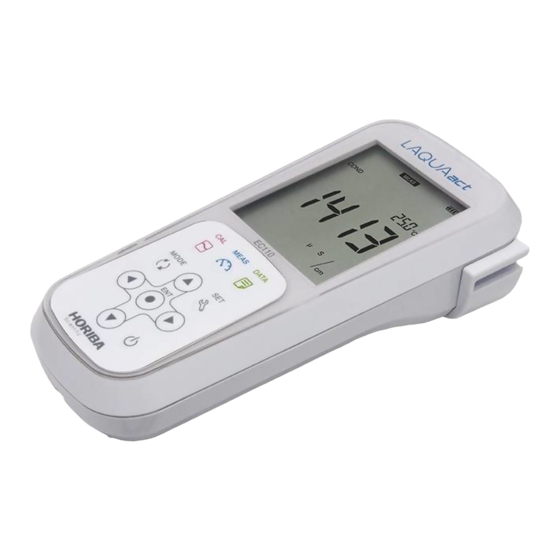
- Page 1 Handheld Conductivity Meter LAQUAact-EC110 LAQUAact-EC120 Instruction Manual CODE:GZ0000427797...
- Page 3 HORIBA, Ltd. warrants that the Product shall be free from defects in material and workmanship and agrees to repair or replace free of charge, at option of HORIBA, Ltd., any malfunctioned or damaged Product attributable to responsibility of HORIBA, Ltd. for a period of two (2) years from the delivery unless otherwise agreed with a written agreement.
- Page 4 Contact your supplier for information on applicable disposal methods. ●Authorised Representative in EU HORIBA UK Limited 2 Dalston Gardens, Stanmore, Middx HA7 1BQ, UK...
- Page 5 Regulations ■ FCC rules Any changes or modifications not expressly approved by the party responsible for compliance shall void the user's authority to operate the equipment. ●WARNING This equipment has been tested and found to comply with the limits for a Class A digital device, pursuant to part 15 of the FCC Rules.
- Page 6 For your safety ■ Hazard classification and warning symbols Warning messages are described in the following manner. Read the messages and follow the instructions carefully. ●Hazard classification This indicates an imminently hazardous situation which, if not avoided, will result in death or serious injury. This is to be limited to the most extreme situations.
-
Page 7: Safety Precautions
For your safety ■ Safety precautions This section provides precautions for using the product safely and correctly and to prevent injury and damage. The terms of DANGER, WARNING, and CAUTION indicate the degree of imminency and hazardous situation. Read the precautions carefully as it contains important safety messages. - Page 8 For your safety ●Battery WARNING Keep batteries out of reach of children. If someone accidentally swallows a battery, consult a doctor immediately. If alkaline fluid from a battery gets into the eyes, do not rub the eyes, rinse with clean water immediately and then consult a doctor. Contact with alkaline fluid could cause blindness.
-
Page 9: Product Handling Information
For your safety ■ Product handling information ●Operational precautions (instrument) ・Only use the product including accessories for their intended purpose. ・Do not drop, crash, or give any physical impact on the instrument. ・The instrument is made of solvent-resistant materials but that does not mean it is resistant to all chemicals. - Page 10 For your safety ●Operational precautions (battery) ・Do not short-circuit a battery. ・Set the + and side of the battery correctly. ・When the battery has run out or the instrument will not be used for a long time, remove the batteries. ・Of the specified battery types, make sure to use two batteries of the same type.
-
Page 11: Description In This Manual
Manual information ■ Description in this manual Note This interprets the necessary points for correct operation and notifies the important points for handling the product. Reference This indicates the part where to refer for information. This indicates reference information. Description of this manual uses the screen display of EC120. - Page 12 M E M O...
-
Page 13: Table Of Contents
Contents Preface ................... I ■ Hazard classification and warning symbols ....IV ■ Safety precautions ............. V ■ Product handling information ......... VII ■ Description in this manual..........IX Part names and basic operation......... 1 ■ Names of each part .............2 ●... - Page 14 Contents Using various functions ............ 45 ■ Data functions..............46 ● Displaying saved data .............. 46 ● Using the automatic data save ..........47 ● Deleting all saved data ............. 50 ■ Measurement setting............52 ● Displaying the latest calibration..........52 ● Changing the calibration method..........53 ●...
- Page 15 Contents ■ When an error message appears ........75 ● ERROR No.0001 Memory error..........75 ● ERROR No.0006 Maximum calibration points exceeded..75 ● ERROR No.0009 Printer error..........76 ● ERROR No.0010 Memory full..........76 ● ERROR No.0011 Cell constant is out of range ....76 ■...
- Page 16 M E M O...
-
Page 17: Part Names And Basic Operation
Part names and basic operation This section describes the name of each part and the main role, function, and basic operation method of each part. ■ Names of each part..............2 ● Instrument....................2 ● Display....................4 ● Operation key ..................6 ■... -
Page 18: Names Of Each Part
Names of each part ■ Names of each part ● Instrument * : EC120 only Name Function Display Displays the measured value and set value and so on. Used for instrument operation. Operation keys (LIGHT key: EC120 only) Electrode connector Connects the BNC connector of the electrode. - Page 19 Names of each part • Identification of manufacturing date Manufacturing date can be identified from MFG No. described in the ID label on the backside of the instrument. Third number from the left in the MFG No. indicates manufacturing year. Forth alphabet from the left in the MFG No.
-
Page 20: Display
Names of each part ● Display Name Function Displays the current operation mode, electrode Status icon status, printer or PC connection status, and remaining battery level. Direction key icon Displays the currently available direction key. Date and time, set item Displays the date and time and the set items. - Page 21 Names of each part •Battery level display Battery level is high. Battery level is a little lower. Battery level is low. The backlight may become unavailable. Battery has run out. Replace the batteries or use AC adapter (option). "ERR No. 0002" is displayed and operation is disabled.
-
Page 22: Operation Key
Names of each part ● Operation key Name Function Changes the operation mode to the measurement mode during operation in a different mode. MEAS key Releases the fixed measurement value mode in the auto hold mode. Changes from the measurement mode to the calibration CAL key mode. -
Page 23: Basic Operation
Basic operation ■ Basic operation ● Function layer The function layer of the data mode and setting mode is shown as below. "dX" and "PXX" indicates the program number which is shown in the screen of the instrument. • Data mode Screen Layer Description... - Page 24 Basic operation • Setting mode Screen Layer Description P1: COND Conductivity measurement settings P11: CELL Cell constant setting P12: UNIT Selection of unit: S/cm, S/m, mS/cm FIX P13: CAL DATA Calibration data display P14: AUTO CAL Selection of auto calibration, manual calibration P15: CAL CLR Deletion of calibration data...
- Page 25 Basic operation Screen Layer Description P5: GEN General settings P51: MEAS Selection of auto hold type: auto stability, auto hold P52: AUTO OFF Automatic power off setting: 0 min to 30 min P53: RESET Initialization settings P54: DATE Date and time setting (EC120 only) P55: PRINT Test print...
-
Page 26: Changing The Operation Mode
Basic operation ● Changing the operation mode Change the operation mode from four available modes depending on the purpose of use. The status icon indicates the current mode. You can change the operation mode using the corresponding key. However changing to the calibration mode, data mode, or setting mode is possible only from the measurement mode. -
Page 27: Changing The Measurement Parameter
Basic operation ● Changing the measurement parameter This instrument measures multiple parameters. In the measurement mode, the measurement parameter can be changed by pressing the key. (EC120 only) -
Page 28: Using The Backlight
Basic operation ● Using the backlight When it is difficult to see the screen in a dark location, you can turn on the backlight by pressing the key. If the backlight is not operated for 5 minutes, it automatically turns off. -
Page 29: Entering Numeric Values
Basic operation ● Entering numeric values When entering numeric values to make various settings and set a calibration value, change the selected digit using the keys and increment or decrement the value (0 to 9) using the keys. -
Page 30: Saving Measurement Data In The Internal Memory
Basic operation ● Saving measurement data in the internal memory Up to 100 (EC110) or 1000 (EC120) data items measured by the instrument can be stored in the internal memory. Saving the measurement data is possible only when the instrument is in the measurement mode. 1. -
Page 31: Measurement
Measurement This section describes the basic method of measurement of each measurement parameters. ■ Preparation ................. 16 ● Confirmation before starting measurement ........16 ● Turning ON the instrument..............17 ● Connecting an electrode ..............20 ■ Conductivity measurement............21 ●... -
Page 32: Preparation
Preparation ■ Preparation ● Confirmation before starting measurement ・ Have you prepared the appropriate electrode for the measurement parameter? ⇒ If not, purchase the appropriate electrode. ・ Is the prepared electrode in good condition? ⇒ If the responsive part is stained or damaged, it may not be possible to obtain ... -
Page 33: Turning On The Instrument
Preparation ● Turning ON the instrument • Inserting the batteries This instrument is operated by batteries. You can use AAA alkaline batteries or AAA Ni- MH rechargeable batteries. Perform the following procedure to insert batteries in the instrument. 1. Turn the knob on the battery cover on the back of the instrument counterclockwise to unlock the battery cover. - Page 34 Preparation • Using the AC adapter (option) It is possible to use the AC adapter to operate the instrument. Perform the following procedure to connect AC adapter to the instrument. The AC adapter is an option. To purchase it, contact your dealer. (Refer to "Options" (page 87).) 1.
- Page 35 Preparation • Pressing the POWER key After setting the batteries or connecting the AC adapter, press the key over one second. The LCD is fully displayed for one second, and the screen displays the version number of software and the model, and then displays the measurement mode. Note ・...
-
Page 36: Connecting An Electrode
Preparation ● Connecting an electrode To perform measurement, it is necessary use the appropriate electrode for measurement parameters. Recommended electrodes for each measured sample are listed in our product catalog and on our website. Refer to them when preparing electrodes. Use the following procedure to correctly connect the electrode to the instrument. -
Page 37: Conductivity Measurement
Conductivity measurement ■ Conductivity measurement The conductivity cell can be used to measure the conductivity, salinity, TDS, and resistivity of a sample. Salinity, TDS, and resistivity are calculated from the measured value of conductivity. Press the key to select the measurement parameter (refer to "Changing the measurement parameter"... -
Page 38: Setting The Instrument
Conductivity measurement ● Setting the instrument • Setting the temperature display When a conductivity cell with a temperature sensor is used, or a conductivity cell without a temperature sensor is used with a temperature electrode, the automatic temperature measurement function can be used. During measurement, the temperature sensor measures the temperature of the sample and displays the result on the instrument. - Page 39 Conductivity measurement 3. In the case of "MTC", enter the temperature to be compensated for and press key to confirm. Enter a number To return to the measurement mode, press the key.
- Page 40 Conductivity measurement • Setting the conductivity unit (default: S/cm) Select the conductivity unit from three options, S/cm, S/m, mS/cm FIX (fixed at mS/cm) depending on your application. When measuring resistivity, these units correspond to Ω·cm, Ω·m, Ω·cm (for mS/cm FIX). 1.
- Page 41 Conductivity measurement 4. Press the keys to select the unit and press the key to confirm. Select "S/cm" and press the (Ex.: "S/cm" is selected) To return to the measurement mode, press the key.
- Page 42 Conductivity measurement • Setting the salinity unit (default: PPT) Select the salinity unit from % or PPT depending on your application. This function is available for EC120. 1. Press the key to enter the setting mode. 2. Press the keys to select "SALT" (salinity setting) and then press the key.
- Page 43 Conductivity measurement 4. Press the keys to select the unit and press the key to confirm. Select "PPT" and press the (Ex.: "PPT" is selected) To return to the measurement mode, press the key.
- Page 44 Conductivity measurement • Setting the cell constant (default: 1.000×1.0 cm A cell constant is unique for each conductivity cell. To measure conductivity correctly, the cell constant of the conductivity cell must be set in the instrument. 1. Press the key to enter the setting mode. 2.
- Page 45 Conductivity measurement 4. Press the keys to select the digit number of the cell constant of the conductivity cell and then press the key. Select "1.0" and press the 1.0 (Ex.: " " is selected) 5. Press the keys to enter the cell constant value of the conductivity cell and then press the key to confirm.
- Page 46 Conductivity measurement To return to the measurement mode, press the key. Note • The unit used for the cell constant corresponds the unit set in "Setting the conductivity unit (default: S/cm)" (page 24). • When the cell constant is changed through the cell constant setting, all the previous calibration data is deleted.
- Page 47 Conductivity measurement • Setting the temperature conversion (Default: ON, 2.00%/°C) The measured value of a sample that is not at 25°C can be converted to a value at the selected temperature. To use the temperature conversion function correctly, temperature coefficient (the rate of change per 1°C of the conductivity) must be set for each sample. The setting of "Setting the temperature display"...
- Page 48 Conductivity measurement To return to the measurement mode, press the key. Note • The temperature coefficient varies by sample. Before using the temperature conversion function, always check the temperature coefficient of the sample and set it in the instrument. • When the temperature conversion function is used with automatic temperature measurement (ATC), deviations may occur within the accuracy of the temperature sensor.
- Page 49 Conductivity measurement • Setting the reference temperature (Default: 25°C) Temperature to be converted can be selected from 15°C to 30°C. 1. Press the key to enter the setting mode. 2. Press the keys to select "COND" (conductivity setting) and then press the key.
- Page 50 Conductivity measurement • Setting the TDS method TDS is calculated from the measured conductivity value. The available calibration methods are "Linear": KCl with factor adjustable from 0.4 to 1.0 (default: 0.5), "442": Myron L 442 non-linear standard curve, "En27888": European environmental standard non-linear curve, and "NaCl": non-linear salinity curve.
- Page 51 Conductivity measurement 4. Press the keys to select the TDS method and then press the key. 5. When selecting "LINEAR," enter the factor and then press the key to confirm. Select "LINEAR" and press the Enter a number To return to the measurement mode, press the key.
- Page 52 Conductivity measurement • Setting the salinity method Salinity is calculated from the measured conductivity value. The available calibration methods are "NaCl" and "Sea water". This function is available for EC120. 1. Press the key to enter the setting mode. 2. Press the keys to select "SALT"...
- Page 53 Conductivity measurement 4. Press the keys to select the salinity calculation method and then press the key to confirm. To return to the measurement mode, press the key.
-
Page 54: Performing Conductivity Calibration
Conductivity measurement ● Performing conductivity calibration The factory-certified cell constant is indicated on the label on the electrical conductivity cell. Cell constant may change depending on the usage condition. In such case, the conductivity cell can be calibrate automatically or manually. You can select calibration method. - Page 55 Conductivity measurement Note In automatic calibration, the measured value of a standard solution that is not at 25°C is always converted to 25°C with 2.00%/°C temperature coefficient.
- Page 56 Conductivity measurement • Manual calibration 1. Clean the conductivity cell with pure water (or deionized water) and wipe it with filter paper or tissue paper. Do not touch the black electrode part. Refer to the instruction manual of the conductivity cell for how to clean the conductivity cell.
- Page 57 Conductivity measurement Stabilized Enter a number For multiple point calibration, repeat the steps 1. to 5. The calibration points are up to 5 points. Note The calibration for TDS, salinity, and resistivity is performed with the result of the calibration of conductivity.
-
Page 58: Performing Measurement
Conductivity measurement ● Performing measurement Immerse the conductivity cell in a sample to perform measurement. Auto stability mode and auto hold mode are available to judge the stability of the measurement value. For details of settings, refer to "Setting the auto stability and auto hold function" (page 58). -
Page 59: Saving Measured Values
Conductivity measurement ● Saving measured values To save the measurement data, press the key in the screen that you want to save. For details, refer to "Saving measurement data in the internal memory" (page 14). - Page 60 M E M O...
-
Page 61: Using Various Functions
Using various functions This section describes functions available in this instrument. ■ Data functions............46 ● Displaying saved data................. 46 ● Using the automatic data save............47 ● Deleting all saved data................ 50 ■ Measurement setting..........52 ● Displaying the latest calibration ............52 ●... -
Page 62: Data Functions
Data functions ■ Data functions ● Displaying saved data You can display the data saved in the internal memory. 1. Press the key to enter the data mode. 2. Press the keys to select "DATA OUT" (display saved data) and then press key. -
Page 63: Using The Automatic Data Save
Data functions ● Using the automatic data save This function saves the data in the internal memory of the instrument at the specified interval automatically. While using this function, auto stability and hold mode are not available and the automatic power off setting is disabled. If the batteries run out while using the automatic data save function, the data saved until just before the batteries run out. - Page 64 Data functions 4. Enter the period of saving in minutes and press the key. A period from 0 min to 3600 min can be set. "0" indicates no period. Enter a number Enter a number 5. Press the key to enter the measurement mode.
- Page 65 Data functions 6. Pressing the key starts saving the data (when the setting is "ON"). Pressing the key again stops the data saving process. During automatic data saving measurement, data is displayed for one second each time a measurement takes place. When more than 1000 data items are saved, "ERR No. 0010" is displayed and data saving is stopped.
-
Page 66: Deleting All Saved Data
Data functions ● Deleting all saved data Delete all data saved in the internal memory. Data cannot be deleted selectively. Copy or transfer the data to a PC for storage if necessary. 1. Press the key to enter the data mode. 2. - Page 67 Data functions 3. Select "YES" to delete the saved data, or select "NO" to cancel deleting it. And then press the key to confirm. When "YES" is selected, "END" appears after deletion is complete. Select "YES" and press the To return to the measurement mode, press the key.
-
Page 68: Measurement Setting
Measurement setting ■ Measurement setting ● Displaying the latest calibration You can display the latest calibration data. 1. Press the key to enter the setting mode. 2. Press the keys to select "COND" (conductivity setting) and then press key. 3. Press the keys to select "CAL DATA"... -
Page 69: Changing The Calibration Method
Measurement setting ● Changing the calibration method Select automatic calibration or manual calibration for the calibration method. 1. Press the key to enter the setting mode. 2. Press the keys to select "COND" (conductivity setting) and then press the key. 3. -
Page 70: Deleting Calibration Data
Measurement setting ● Deleting calibration data Delete the calibration data set in the instrument. 1. Press the key to enter the setting mode. 2. Press the keys to select "COND" (conductivity setting) and then press key. 3. Press the keys to select "CAL CLR" (delete calibration data) and then press the key. - Page 71 Measurement setting 4. Select "YES" to delete the calibration data, or select "NO" to cancel deleting it. And then press the key. When "YES" is selected and is pressed, "END" appears after deletion is complete. Select "YES" and press the To return to the measurement mode, press the key.
-
Page 72: Temperature Settings
Temperature settings ■ Temperature settings ● Calibrating temperature sensor The temperature sensor or temperature compensation electrode in the combination electrode has ±1°C accuracy without calibration. You can use a known temperature solution to calibrate the temperature sensor. 1. Insert the temperature connector into the temperature connector (T) on the instrument. - Page 73 Temperature settings To return to the measurement mode, press the key. Note When initializing temperature calibration data, all settings need to be initialized. Perform initialization by referring to "Resetting to factory default settings" (page 62). When initialization is performed, all saved data is deleted. Copy or transfer necessary data to a PC for storage.
-
Page 74: General Settings
General settings ■ General settings ● Setting the auto stability and auto hold function This instrument has auto stability mode and auto hold mode. • Auto stability mode (displayed as AS) When the criterion for stability judgment is fulfilled during measurement, the component icon lights and the measured value is fixed. - Page 75 General settings 4. Select "AS" to set the auto stability, or select "AH" to set the auto hold. And then press the key to confirm selection. (Ex.: "AS" is selected) To return to the measurement mode, press the key. Note In the calibration mode, the auto stability mode always works.
-
Page 76: Changing The Automatic Power Off Setting (Default: 30 Min)
General settings ● Changing the automatic power off setting (default: 30 min) You can set the instrument to automatically turn OFF when there is no key operation for a certain period of time. This function is disabled during automatic data memory saving or remote operation using an external device. - Page 77 General settings 4. Enter the automatic power off time and press the key. The setting range is 0 min to 30 min. "0" indicates the automatic power off is "OFF." Enter a number To return to the measurement mode, press the key.
-
Page 78: Resetting To Factory Default Settings
General settings ● Resetting to factory default settings The instrument settings can be reset to the factory default settings. The calibration data and the saved data are deleted. Make sure there will be no problems before using this function. When this function is used, the temperature calibration data is also initialized. 1. - Page 79 General settings 4. Select "YES" to initialize the settings to the factory default settings, or select "NO" to cancel initialization. And then press the key to confirm selection. When "YES" is selected, "END" appears after the settings are initialized and then the instrument is automatically power OFF.
-
Page 80: Setting The Date And Time
General settings ● Setting the date and time When using the instrument for the first time or after replacing the batteries, set the date and time. After setting, the date and time data is displayed correctly when saving data in the internal memory. - Page 81 General settings 6. Press the key to confirm. Enter a Enter a number and number and press press Enter a Enter a number and number and press press To return to the setting mode, press the key.
-
Page 82: Performing Test Printing Of The Printer Unit
General settings ● Performing test printing of the printer unit In order to check whether the printer unit is operating correctly or there is a printer communication problem, you can perform test printing. Connect the instrument and a printer correctly and perform the following procedure for test printing. - Page 83 General settings 3. Press the keys to select "PRINT" (test print) and then press the key. Printing starts automatically. When printing ends, the printer icon lights and "END" appears. Press the key or key. Printed key or To return to the measurement mode, press the key.
-
Page 84: Other Settings
Other settings ■ Other settings ● Printing measured values and calibration data Print out the measured value or calibrated value displayed on the instrument, or the measurement data or the calibration data saved in the instrument. If the repeatability is inspected, the inspection data is printed out with the calibration data. - Page 85 Other settings < Calibration data > Printout format Description : LAQUAact-EC120 Instrument model Inst. model : KL1TSE02 Instrument serial number Inst. SN : Cell constant CELL R1 (0.00-19.99 μS/cm) Measurement range (range 1) Cell constant (range 1) 1.000×1 cm R2 (18.0-199.9 μS/cm) Measurement range (range 2) Cell constant (range 2) 1.000×1 cm...
-
Page 86: Transferring Saved Data To A Pc
Other settings ● Transferring saved data to a PC By using a serial cable to connect the instrument to a PC, you can transfer the saved data to the PC and edit it (EC120 only). Connect the RS-232C connector at the instrument side to the serial port on the PC. -
Page 87: Operating The Instrument From An External Device
Other settings ● Operating the instrument from an external device You can remotely operate the instrument from an external device (such as PC) via RS- 232C communication. Use a serial cable to connect the serial connector on the instrument and the serial port on the PC. When using this function, pay attention to the following points. - Page 88 M E M O...
-
Page 89: Maintenance
Maintenance Maintenance This section describes maintenance of the instrument and the electrodes that are used with the instrument. To use them for a long period, perform the described maintenance procedures appropriately. ● Contact for maintenance Please contact your dealer for the product maintenance. ●... -
Page 90: Maintenance And Storage Of The Conductivity Cell
Maintenance ● Maintenance and storage of the conductivity cell For the detailed procedures for maintaining and storing cells, refer to the instruction manual for each cells. This section describes an overview of the procedures for maintenance and storage to be performed as part of daily use. •... -
Page 91: How To Resolve Errors Or Troubles
When an error message appears How to resolve errors or troubles This section describes the causes of typical problems and the actions to be taken, including questions frequently asked by customers. Check these before contacting us. ■ When an error message appears If "ERROR No.00XX"... -
Page 92: Error No.0009 Printer Error
When an error message appears ● ERROR No.0009 Printer error An error occurred during printer communication. Cause How to solve problem There is a problem with the Check the printer connection, and connect the instrument printer unit connection. and printer again. The defect of the printer Consult your dealer. -
Page 93: Troubleshooting
Troubleshooting ■ Troubleshooting This section describes causes and actions to take for problems that customers frequently ask us. ● The indicated value fluctuates < Problem with the electrode > Cause How to solve problem The conductivity cell is dirty. Clean the conductivity cell. The conductivity cell is broken. -
Page 94: The Indicated Value Does Not Change/No Response
Troubleshooting ● The indicated value does not change/No response Cause How to solve problem The conductivity cell is broken. Replace the conductivity cell. The conductivity cell is not Connect the conductivity cell correctly. connected correctly. The instrument is in HOLD state. Cancel the HOLD state. Instrument defect Consult your dealer. -
Page 95: Nothing Appears When The Power Is Turned On
Troubleshooting ● Nothing appears when the power is turned ON Cause How to solve problem Power is not supplied. Insert batteries or connect the AC adapter (option). Battery polarity (+, ) is Insert the batteries with the polarity (+, ) correctly reversed. - Page 96 M E M O...
-
Page 97: Appendix
Options for the instrument are also described. ■ Main specifications Item Contents Model LAQUAact-EC110, LAQUAact-EC120 Measurement Conductivity, salinity, TDS, resistivity, temperature parameters Operating ambient 0°C to 45°C temperature, humidity 80% or less in relative humidity (no condensation) AAA alkaline batteries (LR03) or AAA NiMH rechargeable... - Page 98 Main specifications Measurement Item Description parameter Measuring principle Conversion from conductivity value Measuring range 0.00% to 10.00% (0.0 ppt to 100.0 ppt) (Display range) Salinity Accuracy ±0.2% of full scale Resolution 0.01% (0.1 ppt) Measuring principle Conversion from conductivity value Measuring range 0.00 mg/L to 100 g/L (Display range)
-
Page 99: Table Of Conductivity Cell Range
Main specifications ● Table of conductivity cell range ・ Unit: S/m Cell constant Range 1000 m 100 m 10 m 20.0 to 200.0 S/m 2.00 to 19.99 S/m 0.200 to 1.999 S/m 20.0 to 199.9 mS/m 2.00 (0.00) to 19.99 mS/m 0.200 (0.000) to 1.999 mS/m 0.0 to 199.9 µS/m ・... -
Page 100: Table Of Conductivity Cell Range (Resistivity Range)
Main specifications ● Table of conductivity cell range (resistivity range) ・ Unit: Ω·m Cell constant Range 10 m 100 m 1000 m 0.200 to 2.000 MΩ·m 20.0 to 199.9 kΩ·m 2.00 to 19.99 kΩ·m 0.200 to 1.999 kΩ·m 20.0 (0.0) to 199.9 Ω·m 2.00 (0.00)... -
Page 101: Instrument Default Settings
Instrument default settings ■ Instrument default settings Measurement Selection item/Setting Item Default values range parameter Auto hold AS/AH Temperature input value 0.0°C to 100.0°C 25.0°C Common Auto power off time 30 min 0 min to 30 min * Auto data memory time 0, 2 s to 3600 s * 0.700 to 1.300 1.000... -
Page 102: Technical Note
Technical note ■ Technical note ● Conductivity standard values at various temperatures Conductivity value at 25°C Temp. (°C) 84.00 (S/cm) 1413 (S/cm) 12.88 (mS/cm) 111.8 (mS/cm) 64.01 7.15 65.4 65.00 8.22 74.1 67.00 1020 9.33 83.2 68.00 1147 10.48 92.5 70.00 1173 10.72... -
Page 103: Options
Options ■ Options A wide variety of electrodes and options are available for use with the instrument. You can select the optimum electrode and options for your application and objectives. These options can be purchased from your nearest agency. Please provide the part name and part number to the representative. - Page 104 M E M O...
- Page 105 2 Miyanohigashi, Kisshoin Minami-ku, Kyoto 601-8510 Japan http://www.horiba.com Distributed by: ABQ Industrial LP USA Tel: +1 (281) 516-9292 / (888) 275-5772 eFax: +1 (866) 234-0451 Web: https://www.abqindustrial.net E-mail: info@abqindustrial.net...
Need help?
Do you have a question about the LAQUAact-EC110 and is the answer not in the manual?
Questions and answers