Table of Contents
Advertisement
Quick Links
Advertisement
Table of Contents

Subscribe to Our Youtube Channel
Related Manuals for Lumel RE70


Summary of Contents for Lumel RE70
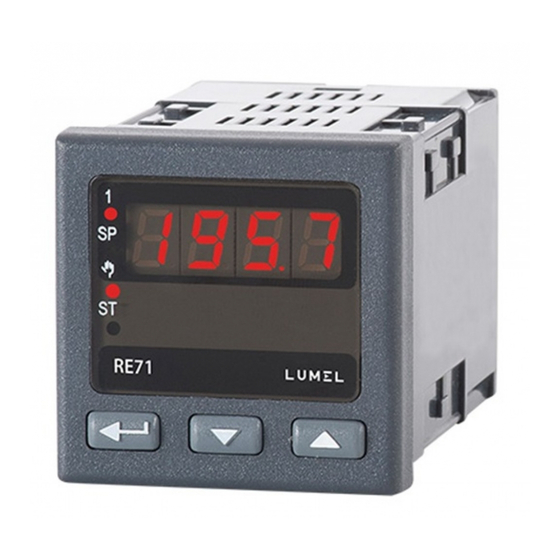
- Page 1 TEMPERATURE CONTROLLER 48 x 48 mm RE70 USER’S MANUAL...
-
Page 2: Table Of Contents
RE70-09-R1 User's Manual Contents: 1. Application ........................3 2. Controller set ........................3 3. Basic requirements, operational safety ................3 4. Installation ........................4 4.1. Controller installation ....................4 4.2. Electrical connections ....................4 4.3. Recommendations for installation ................5 5. -
Page 3: Application
RE70-09-R1 User's Manual 1. Application The RE70 controller is destined for the temperature control. Controller works directly with the resistance sensors or thermoelectric sensors. The controller is equipped with one output that allows for dual-point control and alert signalization. Dual-point control is based on the PID or ON/OFF algorithm. -
Page 4: Installation
RE70-09-R1 User's Manual The installation should have a switch or a circuit-breaker installed. This switch should be located near the device, easy accessible by the operator and suitably marked. 4. Installation 4.1. Controller installation Fix the controller to the board with four screw brackets as shown... -
Page 5: Recommendations For Installation
RE70-09-R1 User's Manual Fig. 3. View of the controller's connection strips. Pt100 Pt100 Pt1000 thermoresistor Pt100 thermoresistor Pt100 thermoresistor thermocouple in 2-wire system in 3-wire system Pt1000 Fig. 4. Input signals supply Fig. 5. Supply load supply Fig. 6. Control/Alarm output... -
Page 6: Starting Work
RE70-09-R1 User's Manual ─ wires leading measuring signals should be twisted in pairs, and for resistance sensors in 3-wire connection, twisted of wires of the same length, cross-section and resistance, and led in a shield, ─ all shields should be one-side earthed or connected to the protection wire, the nearest possible to the controller, ─... -
Page 7: Service
RE70-09-R1 User's Manual measured set-point value accept new change set-point indicator to change set-point press and hold one of the button Fig. 9. Change value of the set point. 6. Service The controller service is presented on the fig. 10. -
Page 8: Programming Matrix
RE70-09-R1 User's Manual Fig. 11 presents the transition matrix in the programming mode. The transition between levels is carrying out by using the buttons ? or > and the level selection by using the button @ . After selecting the level, the transition between parameters is carried out by using the buttons ? or >... -
Page 9: Setting Change
RE70-09-R1 User's Manual 6.3. Setting Change The change of parameter setting begins after pressing the button @ during the display of the parameter name. The setting selection is carried out through the buttons ? and > and accepted by the button @ . -
Page 10: Parameters Description
RE70-09-R1 User's Manual 6.4. Parameters description The list of parameters is presented in the table 1. List of configuration parameters Table 1 Symbol Parameter description Default setting Range of parameter change parameter inp – Input parameters degrees Celsius unit Unit... - Page 11 RE70-09-R1 User's Manual pid – PID parameters 30.0 550.0 °C °C Proportional band °F) (0.1 990.0 °F) Integral time constant 9999 s Derivative time constant 60.0 2500 s Correction of control signal, 100.0 % for P or PD control ...
-
Page 12: Inputs And Outputs Of The Controller
RE70-09-R1 User's Manual 7. Inputs and outputs of the controller 7.1. Inputs Input is the source of the measured value used for control or for alarms. The input is universal and the sensors Pt100, Pt1000 or thermocouples can be connected to it. -
Page 13: Control
RE70-09-R1 User's Manual 8. Control 8.1. ON-OFF algorithm When high accuracy of a temperature control is not required, especially for the high time constant and small delay, it is possible to use ON-OFF control with hysteresis. Disadvantage of this method is the occurrence of oscillations, even at small hysteresis values. - Page 14 RE70-09-R1 User's Manual be set on the value corresponding to the maximum measured value when the control is switched on the full power. The flickering AT symbol informs about the activity of the self-tuning function. The duration of self-tuning depends on dynamic object properties and can last maximally 10 hours.
-
Page 15: Alarms
RE70-09-R1 User's Manual 8.2.2. Proceeding in case of a unsatisfactory PID control It is recommended to choose PID parameters, changing the value in a twice higher or twice less. During the change, one must respect following principles. a) Free jump response: ... -
Page 16: Additional Functions
11. RS-485 interface with MODBUS protocol 11.1. Introduction RE70 controller is equipped with RS-485 serial interface with implemented MODBUS asynchronous communication protocol. The interface is designed for controller configuration prior to using it. Summary of the RE70 controller serial interface: ... -
Page 17: Error Codes
User's Manual information unit: 8N2, data format: integer (16 bits) maximum response time: 500 ms, maximum number of registers read/written in one command: 32. RE70 controller uses following protocol functions: Table 5 Code Meaning n-registers read... - Page 18 RE70-09-R1 User's Manual Register Opera Marking Parameter range Description address tion Unit 4009 UNIT 0…1 0 – degrees Celsius 1 – degrees Fahrenheit Type of main input: 0 – thermoresistor Pt100 1 – thermoresistor Pt1000 2 – J type thermocouple 3 –...
- Page 19 RE70-09-R1 User's Manual Register Opera Marking Parameter range Description address tion 4024 5…999 Pulse period of output [s x10] acc. to the table 4025 ALSP Set point for the absolute alarm [x10] -1800…1800 [x10 C] Deviation from the set point of the relative...
-
Page 20: Error Signaling
RE70-09-R1 User's Manual 12. Error signaling Character messages signaling the incorrect controller operation. Table 11 Error code Reason Procedure Check, if input signal values are situated in the Down overflow of the appropriate range – if yes, check if check if there is... -
Page 21: Technical Data
RE70-09-R1 User's Manual 13. Technical data Input signals acc. to the table 12 Input signals and range limits for inputs Table 12 Sensor type Standard Designation Range Pt100 EN 60751+A2:1997 Pt100 -200850 °C -3281,562 °F Pt1000 EN 60751+A2:1997 Pt1000 -200850 °C -3281,562 °F... -
Page 22: Controller Ordering Code
The way of coding is given in the table 13. Versions and ordering Table 13 Ordering code Description Temperature controller, RE70 00M0 universal input for thermocouple and resistance thermometers, 1x relay output supply 230VAC, documentation and descriptions In Polish and English,... - Page 23 LUMEL S.A. ul. Słubicka 4, 65-127 Zielona Góra, Poland tel.: +48 68 45 75 100, fax +48 68 45 75 508 www.lumel.com.pl Technical support: tel.: (+48 68) 45 75 143, 45 75 141, 45 75 144, 45 75 140 e-mail: export@lumel.com.pl Export department: tel.: (+48 68) 45 75 130, 45 75 132...
Need help?
Do you have a question about the RE70 and is the answer not in the manual?
Questions and answers