Table of Contents
Advertisement
Available languages
Available languages
Quick Links
Advertisement
Table of Contents

Subscribe to Our Youtube Channel
Related Manuals for Lumel RE01


Summary of Contents for Lumel RE01
- Page 1 REGULATOR TEMPERATURY 76 x 34 mm TEMPERTURE CONTROLLER 76 x 34 mm RE01 INSTRUKCJA OBSŁUGI SZYBKI START USER’S MANUAL QUICK START Pełna wersja instrukcji dostępna na Zeskanuj mnie Zeskanuj kod Scan the code Full version of user’s manual available at...
- Page 2 1. WYMAGANIA PODSTAWOWE, BEZPIECZEŃSTWO UŻYTKOWANIA W zakresie bezpieczeństwa użytkowania regulator odpowiada wymaganiom normy PN-EN 61010-1. Uwagi dotyczące bezpieczeństwa: montażu i instalacji połączeń elektrycznych powinna dokonać osoba z uprawnieniami do montażu urządzeń elektrycznych, przed załączeniem regulatora należy sprawdzić poprawność połączeń, przed zdjęciem obudowy regulatora należy wyłączyć jego zasilanie i odłączyć...
-
Page 3: Podłączenia Elektryczne
Rys. 1. Mocowanie regulatora. Wymiary regulatora przedstawiono na rys. 2. Wymiary regulatora przedstawiono na rys. 2. max. 80 max.15 Rys. 2. Wymiary regulatora. Rysunek 2. Wymiary regulatora 4.2 Podłączenia elektryczne Regulator ma dwie listwy rozłączne z zaciskami śrubowymi. Jedna listwa umożliwia 2.2. -
Page 4: Rozpoczęcie Pracy
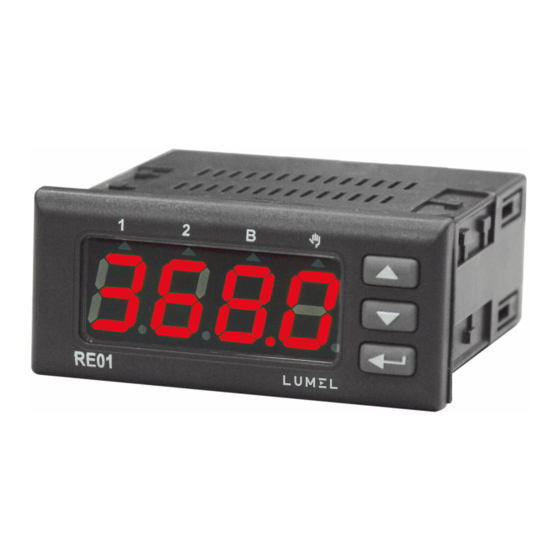
Opis regulatora Rys.4. Wygląd płyty czołowej regulatora. Załączenie zasilania Po załączeniu zasilania regulator wykonuje test wyświetlacza, wyświetla napis re01,wersję programu, a następnie wyświetla wartość mierzoną. Na wyświetlaczu może być komunikat znakowy informujący o nieprawidłowościach (patrz tablica 13- patrz pełna wersja instrukcji obsługi). - Page 5 Rys. 5. Zmiana wartości zadanej.
- Page 6 4. OBSłUGA Obsługa regulatora jest przedstawiona na rys. 6 Rys.6. Menu obsługi regulatora...
- Page 7 Niektóre parametry regulatora mogą być niewidoczne – uzależnione jest to od bieżącej konfiguracji. Opis parametrów zawiera tablica 1 (patrz pełna wersja instrukcji obsługi dostępna na www.lumel.com.pl). Powrót do normalnego trybu pracy następuje automatycznie po upływie 30 sekund od ostatniego naciśnięcia przycisku.
- Page 8 4.2 Matryca programowania 5Hif bNin r-li . . . in.ty un i t Pozycja Przesu- Funkcja Para- Rezy- Jednost- punktu nięcie wejścia Przej- stancja metry wejścia dziesięt- wartości binar- ście do linii wejścia nego mierzonej nego poziomu wyżej . . . out2 out1 outp...
- Page 9 4.3 Zmiana nastawy Zmianę nastawy parametru rozpoczyna się po naciśnięciu przycisku podczas wyświetlania nazwy parametru. Przyciskami dokonuje się wyboru nastawy, a przyciskiem akceptuje. Anulowanie zmiany następuje po jednoczesnym naciśnięcie przycisków lub automatycznie po upływie 30 sekund od ostatniego naciśnięcia przycisku. Sposób zmiany nastawy pokazano na rys.8.
-
Page 10: Dane Techniczne
5. DANE TECHNICZNE Sygnały wejściowe wg tablicy A Sygnały wejściowe oraz zakresy pomiarowe dla wejść Tablica A Oznacze- Norma Zakres czujnika Pt100 EN 60751+A2:1997 Pt100 (-50…100 °C) ( 0…250 °C) ( 0…600 °C) Pt1000 EN 60751+A2:1997 Pt1000 (-50…100 °C) ( 0…250 °C) ( 0…600 °C) (-40…100 °C) NTC 2.7K... - Page 11 Sposób działania wyjścia 1: - rewersyjne: dla grzania - wprost dla chłodzenia Znamionowe warunki użytkowania: - napięcie zasilania 230 V a.c. 10% - częstotliwość napięcia zasilania 50/60 Hz - temperatura otoczenia 0…23…50 °C - temperatura przechowywania -20…+70 °C - wilgotność względna powietrza < 95 % (bez kondensacji pary wodnej) - czas wstępnego nagrzewania 30 min - położenie pracy: dowolne Pobór mocy <...
-
Page 12: Basic Requirements, Operational Safety
1. BASIC REQUIREMENTS, OPERATIONAL SAFETY In the safety service scope, the controller meets to requirements of the EN 61010-1 standard. Observations Concerning the Operational Safety: All operations concerning transport, installation, and commissioning as well as maintenance, must be carried out by qualified, skilled personnel, and national regulations for the prevention of accidents must be observed. - Page 13 4.1 Instalowanie regulatora Przymocować regulator do tablicy czterema uchwytami śrubowymi wg rys. 1. Otwór w tablicy powinien mieć wymiary 71 x 29 mm. Grubość materiału, z którego wykonano +0,7 +0,6 tablicę, nie może przekraczać 15 mm. Fig. 1. Attaching the controller Rys.
-
Page 14: Commencement Of Operation
Fig. 4. View of the controller’s front panel. Power on Once powered on, the controller performs a display test, shows re01, software version and then the measured value. The display may show a sign message on irregularities (see Table no. - Page 15 Fig. 5. Changing the set point.
-
Page 16: Operation
4. OPErATION The controller service is presented on the fig. 6 Fig. 6. Controller operation menu... - Page 17 4.1. Programming of controller parameters Press and hold for approx. 2 seconds to enter the programming matrix. The programming matrix may be protected with an access code. If a wrong code is inserted, one may only view the settings without changing them. Fig.
-
Page 18: Programming Matrix
4.2. Programming Matrix 5Hif bNin in.ty r-li Input . . . un i t Decimal Measu- Binary Input Line resi- Unit parame- point red value input type stance Go one position shift function ters level up out2 . . . outp out1 Output... -
Page 19: Change Of The Setting
4.3. Change of the setting To start changing the parameter setting, press while the parameter name is displayed. Press to select the setting and press to accept it. A change is cancelled when you press at the same time or automatically after 30 seconds from the last button pressed. -
Page 20: Technical Data
5. TECHNICAL DATA Input signals according to Table A Input signals and measuring ranges Table A Sensor Designa- Standard Range tion type Pt100 EN 60751+A2:1997 Pt100 (-50…100 °C) (0…250 °C) (0…600 °C) Pt1000 EN 60751+A2:1997 Pt1000 (-50…100 °C) (0…250 °C) (0…600 °C) (-40…100 °C) NTC 2.7K... - Page 21 Rated operating conditions: 230 V a.c. 10% - supply voltage - supply voltage frequency 50/60 Hz - ambient temperature 0…23…50 °C - storage temperature -20…+70 °C - air relative humidity < 95 % (no condensation of steam) - pre-heating time 30 min - operating position Power input <...
- Page 22 SCHEMATY PODłąCZEŃ ELECTRICAL CONNECTIONS Regulator ma dwie listwy rozłączne z zaciskami śrubowymi. Jedna listwa umożliwia przyłączenie zasilania i wyjść przewodem o przekroju do 2,5 mm , druga listwa umożliwia przyłączenie sygnałów wejściowych przewodem do 1,5 mm The controller has two disconnectable strips with screw terminals. One strip allows for the connection of power supply and output with a wire up to 2.5 mm in size and the other strip for the connection...
- Page 24 LUMEL S.A. ul. Słubicka 4, 65-127 Zielona Góra, Poland tel.: +48 68 45 75 100, fax +48 68 45 75 508 www.lumel.com.pl Informacja techniczna: tel.: (68) 45 75 140, 45 75 141, 45 75 142, 45 75 145, 45 75 146 e-mail: sprzedaz@lumel.com.pl...
Need help?
Do you have a question about the RE01 and is the answer not in the manual?
Questions and answers