Table of Contents
Advertisement
Quick Links
Advertisement
Table of Contents
Troubleshooting

Subscribe to Our Youtube Channel
Related Manuals for Castex QJY2.5-H


Summary of Contents for Castex QJY2.5-H
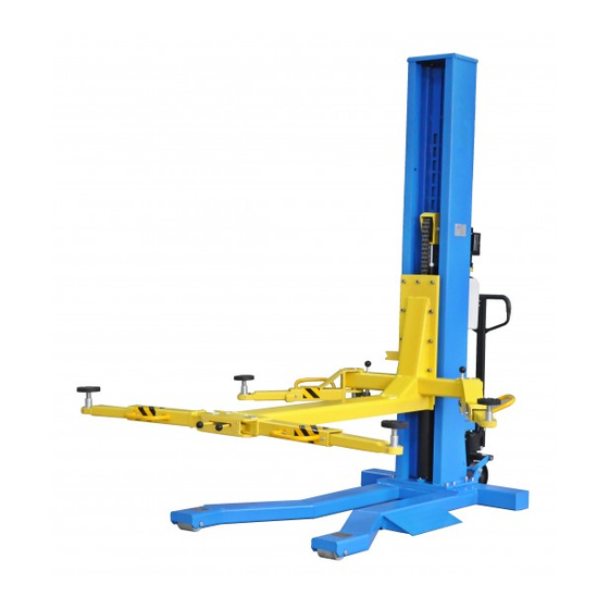
- Page 1 Instructions and Maintenance Original Manual QJY2.5-H Movable single post lift...
-
Page 2: Table Of Contents
Content 1Safety ..........................2 1.1 Introduction ......................2 1.2 Intended Use ......................2 1.3 Safety Instructions for Commissioning..............2 1.4 Safety Instructions for Operation ................2 1.5 Safety Instructions for Servicing ................3 1.6 Safety featuresl ............................ 1.7 Disposal of used oil ....................3 1.8 Machine demolition .................... -
Page 3: 1Safety
1Safety 1.1 Introduction Thoroughly read this manual before operating the lift and comply with the instructions. Always display the manual in a conspicuous location. Personal injury and property damage incurred due to non-compliance with these safety instructions are not covered by the product liability regulations. 1.2 Intended Use This single column vehicle lift is classified as movable model. -
Page 4: Safety Instructions For Servicing
Use caution when removing or installing heavy components (center-of-gravity displacement). The main switch serves as emergency switch. In case of emergency turn to OFF position. Protect all parts of the electrical equipment from humidity and moisture. Protect the lift against unauthorized usage by padlocking the main switch. 1.5 Safety Instructions for Servicing Maintenance or repair work by authorized service personnel only. -
Page 5: Structure Drawing
demolition must be disposed of in accordance with the current standards of the country in which the rack is installed. Finally, it should be recalled that for tax purposes, demolition must be documented; submitting claims and documents according to the current laws in the country in which the rack is installed at the time the machine is demolished. -
Page 6: Main Technical Mechanism Parameters Table
3. Main Technical Mechanism Parameters Table Model Movable QJY-2.5-H Name Lifting capacity: 2500kg Max. lifting height 1800 mm Lifting speed 24mm/s Weight 750kg Noise <70 dB Working environment -5 ℃/+40℃ temperature Working environment Indoors Power 1.5kw Working voltage of control system Voltage 110V/220V/380V/415V Safety catch... -
Page 7: Storage And Stacking Of Packages
loading (e.g. cranes, trucks) and hoisting means. Be sure also to hoist and transport the components securely so that they cannot drop, taking into consideration the package’s size, weight and centre of gravity and it’s fragile parts. 4.3 Storage and stacking of packages Packages must be stored in a covered place, out of direct sunlight and in low humidity, at a temperature between -10°C and +40°C. -
Page 8: Operation Instruction
6. Operation instruction 6.1 Operation Rules for mechanism System 6.1.1 The movable single column lift is provided with separate traveling mechanism. Shake the hauling handle of the steering rear wheel forwards and backwards to make the vertical column off the ground, then you can push or pull the lift. On arriving the working site, press the valve handle to retract the wheel, then the vertical column lands on the ground steadily. - Page 9 1) Vehicle stops in the service position with engine off 2) Turn the handle for hydraulic movable wheel to lift the vertical post base a bit 3) Push the lift into the underside of vehicle 4) Make sure there is no foreign articles under the base and the ground is level 5) Grasp the valve handle to make the base lowered to ground 6) Align 4 pallets on the lifting arm respectively to the supported positions on the vehicle underside...
-
Page 10: Use Lifting Arm
Movable lift pushed into the underside of the vehicle Vehicle driving onto the lift 6.4 Use lifting arm 7.4.1 Movable Lift According to the position under the vehicle chassis where the lifting arm is located, the supporting arm on the lifting arm (close to the vertical post) may be pushed and pulled up and down or to left and right:... -
Page 11: Control Unit
b. The supporting arm in the front of lifting arm may be turned or pushed or pulled inward or outward, or to left and right. c. The height of pallet can be adjusted by turning it clockwise or anticlockwise. 6.5 Control unit Release handle 7 Maintenance and Troubleshooting 7.1 Maintenance... -
Page 12: Troubleshooting
be tighten. After this step, if the leaking problem still occurs, check whether the seal kit of the cylinder is damaged, if it is damaged, it must be replaced. 7.1.4 Month Care Below maintenance should be done once every month. Content of Method Sample drawing... - Page 13 If lifting is possible but impossible to load 2.5T Adjust the fluid valve. It is possible to press the “▲” button while turn the screw clockwise) slowly, until the lifting arm rises. If lifting is still impossible after above actions have been taken Remove fluid valve and put it into diesel oil to wash.
-
Page 14: Appendix
Appendix 1 Exploded drawing... - Page 15 NAME NAME top plate Front arm out tube assembly Fron arm assembly hexagonal screw washer Toothed plate spring washer Plastic ball Limit switch socket handle Limit switch Pull rod Rake tooth Column assembly Hexagonal screw Power unit Hexagon socket screw spring Washer screw...
-
Page 16: Circuit Diagram
2 Circuit diagram 3 Hydraulic diagram Name Name Name Tank Start buffer valve Relief valve Filter One-way valve Anti-explosion valve Oil pump Release valve Motor Return oil throttle valve...
Need help?
Do you have a question about the QJY2.5-H and is the answer not in the manual?
Questions and answers