ASROCK IMB-150 Settings Manual
Jumpers and headers
Hide thumbs
Also See for IMB-150:
- User manual (39 pages) ,
- Settings manual (2 pages) ,
- User manual (39 pages)
Table of Contents
Advertisement
Quick Links
*15G06M012000AK*
P/ N: 15G06M012000AK V1.0
Jumpers and headers setting guide
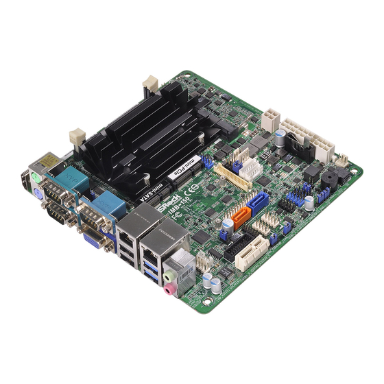
IMB-150
38
37
The terms HDMI™ and HDMI High-Definition
Multimedia Interface, and the HDMI logo are
trademarks or registered trademarks of HDMI
Licensing LLC in the United States and other
countries.
36
35
34
33
32
31
30
29
1 : COM Port PWR Setting Jumpers
PWR_COM1 (For COM Port1)
1-2: +5V
2-3: +12V
3-4: +12V
4-5: +5VSB
PWR_COM2 (For COM Port2)
PWR_COM3 (For COM Port3)
1-2: +5V
2-3: +12V
2 : ME Override (Security Flash Descriptors)
Short: Override
Open: Normal Operation
3 : USB2.0 Connector (USB2_4_5)
DUMMY
GND
GND
+A
+B
-B
-A
USB_PWR
USB_PWR
1
4 : Panel Power Selection (LCD_VCC)
(PNL_PWR1)
1-2: LVDD: +3V
2-3: LVDD: +5V
4-5: LVDD: +12V
5 : Backlight Power Selection
(LCD_BLT_VCC) (BKT_PWR1)
1-2: LCD_BLT_VCC: +5V
2-3: LCD_BLT_VCC: +12V
4-5: LCD_BLT_VCC: DC_IN
6 : ATX Power Connector
2
(Input 9V-19V)
1-2: GND
3-4: DC Input
1
All manuals and user guides at all-guides.com
1
HDMI1
DDR3_A1 (Support DDR3L Only)
COM
COM
Port 2
Port 1
mSATA_SEL1
COM
1
VGA1
Port 3
mini-SATA
Industrial
IMB-150
USB 2.0
CI2
1
Top:
T: USB1
1
RJ-45
B: USB0
CI1
USB 3.0
Top:
T: USB1
RJ-45
B: USB0
PWR_JP1
1
HD_AUDIO1
1
1
USB3_2_3
SPEAKER1
PCIE1
28
27
26
25
7 : 4-Pin CPU FAN Connector (+12V)
GND
+12V
CPU_FAN_SPEED
FAN_SPEED_CONTROL
8 : SATA Power Output Connector
GND
+12V
1
+5V
GND
9 : Backlight Volume Control (BLT_VOL1)
PIN
Signal Name
1
GPIO_VOL_UP
2
GPIO_VOL_DW
3
PWRDN
4
LVDS1 BLUP
5
LVDS1 BLDW
6
GND
7
GND
10 : 20-pin ATX Power Input
Connector
11 : Backlight Power Connector (BLT_PWR1)
PIN
Signal Name
1
GND
2
GND
3
BL CTL
4
BL EN
5
LCD_BLT_VCC
6
LCD_BLT_VCC
12 : Printer Port Header
4
3
ME_OVR1
USB2_4_5
mini-PCIe
1
1
CPU_FAN1
SATA_PWR1
1
BLT_VOL1
1
BLT_PWR1
LPT1
1
SATA2_2
SATA2_1
COM6
USB2_2_3
JGPIO1
COM4
PANEL1
1
BLT_PWM1
1
1
1
1
1
1
1
JGPIO_PWR1
CLRCMOS1
JGPIO_JP1
PWR_COM4
PWR_COM6
1
1
1
1
1
24
23
22
21
20
19
18
17
16
13 : 3-Pin Chassis FAN Connector (+12V)
14 : SATA2 Connectors (SATA2_1, SATA2_2)
15 : BLT_PWM1
1-2: +3V Level
2-3: +5V Level
1
16 : Clear CMOS Header
17 : Digital Input / Output Power Select
1-2: +12V
2-3: +5V
10
20
18 : Digital Input / Output Pin Header
PIN Signal Name PIN Signal Name
10
1
11
8
6
4
1
2
19 : USB2.0 Connector (USB2_2_3)
AFD#
ERROR#
PINIT#
GND
SLIN#
1
SPD7
SPD6
ACK#
SPD5
BUSY
SPD4
PE
SPD3
SLCT
SPD2
SPD1
SPD0
STB#
2
1
3
4
5
6
ATX12V1
7
8
9
10
CMOS
Battery
11
12
CHA_FAN1
13
BIOS
BUZZ1
Chip
15
14
FAN_SPEED
+ 12V
GND
SATA2_2
SATA2_1
1-2: Normal
2-3: Clear CMOS
GND
9
JGPIO_PWR
SIO_GP23
7
SIO_GP27
SIO_GP22
5
SIO_GP26
SIO_GP21
3
SIO_GP25
SIO_GP20
1
SIO_GP24
DUMMY
GND
GND
+A
+B
-B
-A
USB_PWR
USB_PWR
1
Advertisement
Table of Contents

Related Manuals for ASROCK IMB-150


Summary of Contents for ASROCK IMB-150
- Page 1 All manuals and user guides at all-guides.com *15G06M012000AK* P/ N: 15G06M012000AK V1.0 Jumpers and headers setting guide IMB-150 HDMI1 DDR3_A1 (Support DDR3L Only) ME_OVR1 The terms HDMI™ and HDMI High-Definition Multimedia Interface, and the HDMI logo are trademarks or registered trademarks of HDMI Licensing LLC in the United States and other countries.
- Page 2 All manuals and user guides at all-guides.com HDMI1 DDR3_A1 (Support DDR3L Only) ME_OVR1 Port 1 Port 2 mSATA_SEL1 VGA1 USB2_4_5 Port 3 mini-SATA mini-PCIe Industrial IMB-150 ATX12V1 CPU_FAN1 USB 2.0 Top: T: USB1 SATA_PWR1 RJ-45 B: USB0 BLT_VOL1 BLT_PWR1 LPT1 USB 3.0...
Need help?
Do you have a question about the IMB-150 and is the answer not in the manual?
Questions and answers