
Subscribe to Our Youtube Channel
Related Manuals for ASROCK 1U2LW Series


Summary of Contents for ASROCK 1U2LW Series
- Page 1 1U2LW Series User Manual Version 1.0 Published August 2019 Copyright©2019 ASRock Rack INC. All rights reserved.
- Page 2 In no event shall ASRock Rack, its directors, officers, employees, or agents be liable for any indirect, special, incidental, or consequential damages (including damages for loss of profits, loss of business, loss of data, interruption of business and the like), even if ASRock Rack has been advised of the possibility of such damages arising from any defect or error in the documentation or product.
- Page 3 Setting up the Server in a Restricted Access Location • Access can only be gained by service persons or by users who have been instructed about the reasons for the restrictions applied to the location and about any precautions that shall be taken. • Access is through the use of a tool or lock and key, or other means of security, and is controlled by the authority responsible for the location.
-
Page 4: Table Of Contents
Contents Chapter 1 Introduction Shipping Box Contents Specifications Chapter 2 Server System Overview System Components Internal Features System Front Panel System Rear Panel Front Control Panel Buttons and LEDs Chapter 3 Hardware Installation and Maintenance Server Top Cover Hard Drive System Fan Server Board Add-in Card... -
Page 5: Chapter 1 Introduction
In case any modifications of this documentation occur, the updated version will be available on ASRock Rack’s website without further notice. If you require technical support related to this product, please visit our website for specific information about the model you are using. -
Page 6: Shipping Box Contents
1.1 Shipping Box Contents Quantity Item 1U2LW-X470 1U2LW-X570 1U2LW-C242 1U2LW Series Barebone (1U form factor) System Boards (MB)* Power Supply Unit* System Fans* HDD Backplanes (BPB)* Front Panel Board (FPB)* Fan Cable (L:300mm) Fan Cable (L:200mm)* SATA Cable (L:300mm) SATA Cable (L:500mm) -
Page 7: Specifications
1U2LW Series 1.2 Specifications 1U2LW Series System Physical Status Form Factor 1U Rackmount Dimension 394 x 482.6 x 44.4mm (D/W/H) (D x W x H) Support MB Size mATX / ATX Front Panel Buttons • Power On button • System reset button LEDs •... -
Page 8: Chapter 2 Server System Overview
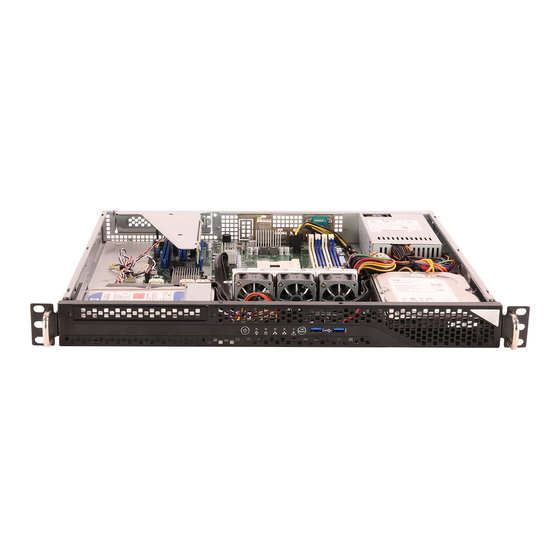
Chapter 2 Server System Overview This chapter provides diagrams showing the location of important components of the server system. 2.1 System Components Power Supply Unit 3 x System Fans Top Cover 2 x 3.5” HDDs Server Board Front Controls and Indicators 1 x Slim ODD (Optional) -
Page 9: Internal Features
1U2LW Series 2.2 Internal Features From 3.5" SATA HDD (HDD0) Front Panel Board (FPB) 3.5" SATA HDD (HDD1) Slim Optical Disc Drive (ODD) (optional) System Fan 1 System Fan 2 System Fan 3 Power Supply Unit (PSU) Serverboard PCIE x16 Add-in Card... -
Page 10: System Front Panel
2.3 System Front Panel Description 1 x Slim Optical Disc Drive (ODD) Control Panel Buttons and LEDs 2 x USB Ports 2.4 System Rear Panel Description Power Supply Unit I/O Shield (depends on the specification of the server board) Rear Vent PCI Express Slot (for the riser card) -
Page 11: Front Control Panel Buttons And Leds
1U2LW Series 2.5 Front Control Panel Buttons and LEDs Front Control Panel Description Power Button Power Status LED HDD Status LED LAN1 Activity LED LAN2 Activity LED System Status LED System Reset Button USB Port (USB_1) USB Port (USB_2) *Please be noted that the functions are supported depending on the type of the server board. - Page 12 HDD Status LED Status Description Blinking Yellow HDD access HDD idle LAN1, LAN2 LED Status Description Blue Link between system and network or no access Blinking Blue Network access...
-
Page 13: Chapter 3 Hardware Installation And Maintenance
1U2LW Series Chapter 3 Hardware Installation and Maintenance This chapter helps you assemble the chassis and install components. Before You Begin Before you work with the server, pay close attention to the “Important Safety Instructions” at the beginning of this manual. -
Page 14: Server Top Cover
3.1 Server Top Cover Removing the Server Top Cover 1. Before removing the top cover, power off the server and unplug the power cord. 2. The system must be operated with the chassis top cover installed to ensure proper cooling. 1. - Page 15 1U2LW Series Installing the Server Top Cover 1. Lower the top cover on the chassis, making sure the side latches align with the cutouts. 2. Slide the top cover toward the front. 3. Secure the top cover with the screws.
-
Page 16: Hard Drive
3.2 Hard Drive 3.2.1 Installing a Hard Disk Drive into 3.5" Hard Drive Carrier Removing a 3.5” Hard Drive Carrier from the Chassis 1. Release the screws that secure the hard drive carriers to the chassis. 2. Lift up and remove the carriers. HDD0 HDD1... - Page 17 1U2LW Series Installing a 3.5” Hard Drive to the Hard Drive Carrier (HDD0) 1. Place the 3.5" HDD into the carrier with the printed circuit board side facing down. Carefully align the mounting holes in the hard drive and the carrier.
- Page 18 Installing a 3.5” Hard Drive to the Hard Drive Carrier (HDD1) 1. Place the 3.5" HDD into the carrier with the printed circuit board side facing up. Carefully align the mounting holes in the hard drive and the carrier. 2. Secure the hard drive using the screws. 3.
-
Page 19: System Fan
1U2LW Series 3.3 System Fan Replacing the Simple-Swap Fan 1. Press and hold the clip on the fan. 2. Press and hold the clip on the middle fan. Fan Mount Mounting Hole... -
Page 20: Server Board
3.4 Server Board Follow the steps below to install the server board to the chassis. 1. Hold the server board only by the edges. 2. Gently place the server board into the chassis. Sit the server board on the server board tray. -
Page 21: Add-In Card
1U2LW Series 3.5 Add-in Card 1. You can install an Add-in Card to the chassis only when you have a riser card installed on the server board. 2. Before installing the Add-in Card, power off the server and unplug the power cord. - Page 22 Installing the Add-in Card Before installing an Add-in Card, you need to install a mezzaine card and a riser card first. Please refer to the followings for instructions. 1. Install the Add-in Card to the assembly. 2. Secure the Add-in Card to the assembly with the screw. 3.
-
Page 23: Chapter 4 Chassis Cables
1U2LW Series Chapter 4 Chassis Cables This section lists supported cables for your chassis system. Cable type and quantity vary depending on the server board that comes with your system. 1. SATA Cable (SATA 6G 180-180, L=300mm) BPB (1U2LW-470 / 1U2LW-C242) HDD (1U2LW-X570/2L2T) 2. - Page 24 6. Aux_Panel Cable...
-
Page 25: Chapter 5 Board Specifications
1U2LW Series Chapter 5 Board Specifications 5.1 Front Panel Board (FPB) Description USB 3.2 Gen1 Port (USB_1) USB 3.2 Gen1 Port (USB_2) Reset Button (RST_SW) System Healthy LED (SYS_LED) Mezz LAN2 LED (LAN2_LED) Mezz LAN1 LED (LAN1_LED) HDD Status LED (HDD_LED) -
Page 26: Installing The Cpu (Amd Am4 Socket)
Appendix A Installing the CPU (AMD AM4 Socket) - Page 27 1U2LW Series...
-
Page 28: Installing The Cpu Heatsink
Installing the CPU Heatsink... - Page 29 1U2LW Series Please be aware of the correct direction when you install the CPU heatsink. Make sure the the arrow on the CPU heatsink is pointing to the opposite side of the system fan. Air Flow Direction...
-
Page 30: Installation Of Memory Modules (Dimm)
Installation of Memory Modules (DIMM) The DIMM only fits in one correct orientation. It will cause permanent damage to the motherboard and the DIMM if you force the DIMM into the slot at incorrect orientation. For more information about DIMM installation, please refer to the User Manual that comes with the serverboard you use.
Need help?
Do you have a question about the 1U2LW Series and is the answer not in the manual?
Questions and answers