
Related Manuals for ASROCK 1U4LW Series


Summary of Contents for ASROCK 1U4LW Series
- Page 1 1U4LW Series User Manual Version 1.0 Published October 2019 Copyright©2019 ASRock Rack INC. All rights reserved.
- Page 2 In no event shall ASRock Rack, its directors, officers, employees, or agents be liable for any indirect, special, incidental, or consequential damages (including damages for loss of profits, loss of business, loss of data, interruption of business and the like), even if ASRock Rack has been advised of the possibility of such damages arising from any defect or error in the documentation or product.
- Page 3 Setting up the Server in a Restricted Access Location • Access can only be gained by service persons or by users who have been instructed about the reasons for the restrictions applied to the location and about any precautions that shall be taken. • Access is through the use of a tool or lock and key, or other means of security, and is controlled by the authority responsible for the location.
-
Page 4: Table Of Contents
Contents Chapter 1 Introduction Shipping Box Contents Specifications Chapter 2 Server System Overview System Components Internal Features System Front Panel System Rear Panel Front Control Panel Buttons and LEDs Drive Tray LEDs Chapter 3 Hardware Installation and Maintenance Server Top Cover Hard Drive System Fan Backplane... - Page 5 Appendix A Installing the CPU (Single Socket H4 (LGA1151)) Installing the CPU Fan and Heatsink Installation of Memory Modules (DIMM)
-
Page 7: Chapter 1 Introduction
In case any modifications of this documentation occur, the updated version will be available on ASRock Rack’s website without further notice. If you require technical support related to this product, please visit our website for specific information about the model you are using. -
Page 8: Shipping Box Contents
1.1 Shipping Box Contents Item Quantity 1U4LW Series Barebone (1U form factor) System Boards (MB)* Power Supply Unit(s)* 1 or 2 System Fans* HDD Backplane (BPB)* Front Panel Board (FPB)* Fan Cable (L:300mm) SATA Cable Accessory Box 1U Cooler Riser Board... -
Page 9: Specifications
1U4LW Series 1.2 Specifications 1U4LW Series System Physical Status Form Factor 1U Rackmount Dimension 536.35 x 482.6 x 43.7 mm (21" x 19" x 1.72") (D x W x H) Support MB Size mATX / ATX Front Panel Buttons • Power On/Standby button •... -
Page 10: Chapter 2 Server System Overview
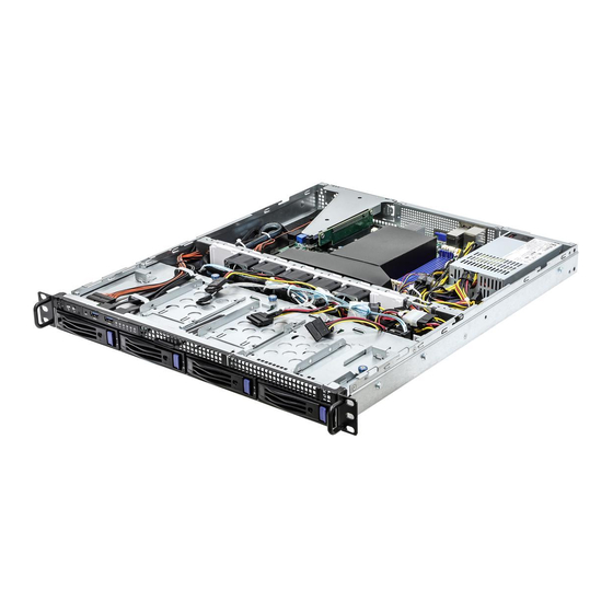
Chapter 2 Server System Overview This chapter provides diagrams showing the location of important components of the server system. 2.1 System Components Top Cover Power Supply Unit(s) System Fans Server Board 4 x 3.5” Hot-Swap HDD Trays Front Controls and Indicators... -
Page 11: Internal Features
1U4LW Series 2.2 Internal Features From Riser Card Serverboard Power Supply Unit (PSU) System Fan 5 System Fan 4 System Fan 3 System Fan 2 System Fan 1 HDD Backplane Board (BPB) Front Panel Board (FPB) 2.5" SATA HDD 2.5" SATA HDD 2.5"... -
Page 12: System Front Panel
2.3 System Front Panel Description Control Panel Buttons and LEDs 2 x USB 3.0 Ports 4 x 3.5" Hot-Swap HDD Trays 2.4 System Rear Panel Description Power Supply Unit Rear Vent I/O Shield (depends on the specification of the server board) PCI Express Slot (for the riser card) -
Page 13: Front Control Panel Buttons And Leds
1U4LW Series 2.5 Front Control Panel Buttons and LEDs Front Control Panel Description ID Button and LED Power Button and LED NMI (Nonmaskable Interrupt) Button System Reset Button LAN1, LAN2, LAN3, LAN4 Activity LED HDD Status LED System Status LED *Please be noted that the functions are supported depending on the type of the server board. - Page 14 Status LED Definitions Power LED Status Description Blue Power on Blinking Blue Standby(Sleep) mode Power off ID LED Status Description Blue System identification is active. System identification is disabled. System Status LED Status Description Running or normal operation Yellow At least one sensor has critical alert HDD Status LED Status Description...
-
Page 15: Drive Tray Leds
1U4LW Series 2.6 Drive Tray LEDs Description HDD Power LED HDD Activity LED Status LED Definitions HDD Power LED Status Description Blue HDD powered-on No power to HDD HDD Activity LED Status Description Solid Green HDD active Blinking Green HDD accessing or reading... -
Page 16: Chapter 3 Hardware Installation And Maintenance
Chapter 3 Hardware Installation and Maintenance This chapter helps you assemble the chassis and install components. Before You Begin Before you work with the server, pay close attention to the “Important Safety Instructions” at the beginning of this manual. 1. Make sure the server is powered off. Power down the server if it is still running. -
Page 17: Server Top Cover
1U4LW Series 3.1 Server Top Cover Removing the Server Top Cover 1. Before removing the top cover, power off the server and unplug the power cord. 2. The system must be operated with the chassis top cover installed to ensure proper cooling. - Page 18 Installing the Server Top Cover 1. Lower the top cover on the chassis, making sure the side latches align with the cutouts. 2. Slide the top cover toward the front. 3. Secure the top cover with the screws.
-
Page 19: Hard Drive
1U4LW Series 3.2 Hard Drive Removing 3.5” Hard Drive Trays from the Chassis 1. Press the locking lever latch on the drive tray to unlock the retention lever. 2. Rotate the lever out and away from the module bay and pull the hard drive out of the... - Page 20 Installing a 3.5” Hard Drive to the Hard Drive Tray 1. Place the 3.5" HDD into the tray with the printed circuit board side facing down. Carefully align the mounting holes in the hard drive and the tray. 2. Secure the hard drive using the four screws. 3.
-
Page 21: System Fan
1U4LW Series 3.3 System Fan Replacing the Simple-Swap Fan 1. Press and hold the clip on the fan. 2. Press and hold the clip on the middle fan. -
Page 22: Backplane
3.4 Backplane Each barebone system supports one 3.5-inch HDD backplanes. The SATA backplanes serve as the interfaces between the motherboard and the HDDs. Before removing and installing the backplane, power off the server and unplug the power cord. Removing the Backplane 1. -
Page 23: Server Board
1U4LW Series 3.5 Server Board Follow the steps below to install the server board to the chassis. 1. Hold the server board only by the edges. 2. Gently place the server board into the chassis. Sit the server board on the server board tray. -
Page 24: Add-On Card
3.6 Add-on Card 1. You can install an add-on card to the chassis only when you have a riser card installed on the server board. 2. Before installing the add-on card, power off the server and unplug the power cord. Removing the Riser-Card Bracket from the Chassis 1. - Page 25 1U4LW Series Installing the Add-on Card 1. Install the add-on card to the riser-card bracket. 2. Secure the add-on card to the bracket with a screw . 3. Align the riser-card assembly with the openings of the chassis. 4. Attach the assembly to the chassis with the screw that was previously set aside.
-
Page 26: Air Duct
3.7 Air Duct 1. If an add-on card is already installed, remove the add-on card assembly from the chassis before installing the air duct. If an add-on card is not installed yet, install the add-on card first. Please see the chapter entitled "Add-on Card" for more instructions. 2. - Page 27 1U4LW Series 3. Then install the add-on card assembly to the chassis. Air Duct (add-on card) Riser Card Assembly 4. Make sure the add-on card assembly is well aligned with the air duct.
- Page 28 5. Align the air duct over the heat sink and carefully lower the air duct in place.
-
Page 29: Chapter 4 Chassis Cables
1U4LW Series Chapter 4 Chassis Cables This section lists supported cables for your chassis system. Cable type and quantity vary depending on the server board that comes with your system. 1. SATA Cable Backplane 2. Fan Cable... -
Page 30: Chapter 5 Board Specifications
Chapter 5 Board Specifications 5.1 Hard Drive Backplanes (BPB) Description SGPIO Disabled/Enabled Jumper (JP1) SATA Connector (SATA_1) SGPIO Code Programming Pin (CN6) SATA Connector (SATA_2) SATA Connector (SATA_3) SATA HDD Power Connector (CN2) SATA HDD Power Connector (CN1) Slim ODD Power Connector (CN4) Slim ODD Power Connector (CN3) SATA Hot-swap Connector SATA Hot-swap Connector... - Page 31 1U4LW Series Jumper Setup The illustration shows how jumpers are setup. When the jumper cap is placed on the pins, the jumper is “Short”. If no jumper cap is placed on the pins, the jumper is “Open”. The illustration shows a 3-pin jumper whose pin1 and pin2 are “Short”...
- Page 32 Slim ODD Power The 4-pin connectors Connectors provide power to the slim (4-pin CN3) ODD. (4-pin CN4)
-
Page 33: Front Panel Board (Fpb)
1U4LW Series 5.2 Front Panel Board (FPB) Description Power Button with LED (Power_SW) UID Button with LED (ID_SW) System Healthy LED (SYS_LED) HDD Status LED (HDD_LED) Mezz LAN 1 LED (LAN_LED1) Mezz LAN2 LED (LAN_LED2) Reset Button (RST_SW) NMI Button (MNI_SW) USB 2.0 Port (USB_1) - Page 34 Appendix A Installing the CPU (Single Socket H4 (LGA1151))
- Page 35 1U4LW Series...
- Page 36 Installing the CPU Fan and Heatsink...
- Page 37 1U4LW Series Installation of Memory Modules (DIMM) The DIMM only fits in one correct orientation. It will cause permanent damage to the motherboard and the DIMM if you force the DIMM into the slot at incorrect orientation. For more information about DIMM installation, please refer to the User Manual that...
Need help?
Do you have a question about the 1U4LW Series and is the answer not in the manual?
Questions and answers