
Related Manuals for Sony STR-DB780


Summary of Contents for Sony STR-DB780
- Page 1 4-241-673-12(1) FM Stereo FM-AM Receiver Operating Instructions STR-DB780 © 2002 Sony Corporation...
- Page 2 Do not install the appliance in a confined space, such as a bookcase or built-in cabinet. Except for European model NERGY registered mark. As an NERGY Sony Corporation has determined that this product meets the ® guidelines for energy efficiency. ® is a U.S.
-
Page 3: About This Manual
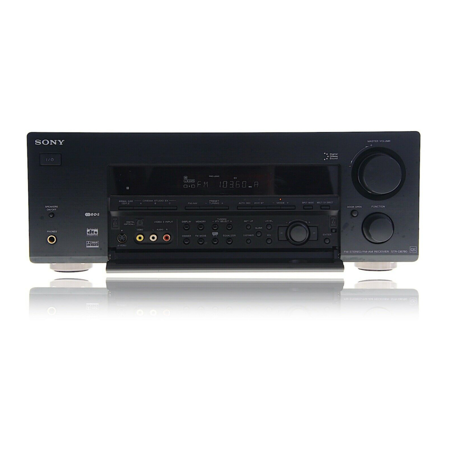
About This Manual • The instructions in this manual are for model STR-DB780. Check your model number by looking at the lower right corner of the front panel. In this manual, the models of area code U is used for illustration purposes unless stated otherwise. -
Page 4: Table Of Contents
Table of Contents List of Button Locations and Reference Pages Main unit ... 6 Getting Started 1: Check how to hookup your components ... 8 1a: Connecting components with digital audio output jacks ... 10 1b: Connecting components with multi channel output jacks ... - Page 5 Operations Using the Remote RM-U305C* Before you use your remote ... 53 Remote button description ... 53 Changing the factory setting of a function button ... 56 Additional Information Precautions ... 57 Troubleshooting ... 57 Specifications ... 60 Index ... 63 Models of area code CEL, CEK only.
-
Page 6: List Of Button Locations And Reference Pages
List of Button Locations and Reference Pages How to use this page Use this page to find the location of buttons and other parts of the system that are mentioned in the text. Main unit ALPHABETICAL ORDER A – L AUTO DEC qs (33) CINEMA STUDIO EX A/B/C qg (34) - Page 7 qs qa Open the front door ql w; ws wd – – –...
-
Page 8: Getting Started
Getting Started 1: Check how to hookup your components Steps 1a through 1c beginning on page 10 describe how to hook up your components to this receiver. Before you begin, refer to “Connectable components” below for the pages which describe how to connect each component. -
Page 9: Required Cords
• When connecting optical digital cords, insert the cord plugs straight in until they click into place. • Do not bend or tie optical digital cords. If you have a Sony components with CONTROL A1 jack See “CONTROL A1 control system” on page 49. -
Page 10: 1A: Connecting Components With Digital Audio Output Jacks
1a: Connecting components with digital audio output jacks Hooking up a DVD player, LD player, TV, or satellite tuner For details on the required cords (A–H), see page 9. 1 Connect the audio jacks. * Connect to either the ASSIGNABLE COAXIAL IN (DVD/LD CD/SACD) or the DVD/LD OPTICAL IN jack. We recommend making connections to the ASSIGNABLE COAXIAL IN (DVD/LD CD/SACD) jack. - Page 11 2 Connect the video jacks. (Except for models of area code CEL, CEK) The following illustration shows how to connect a TV or satellite tuner and a DVD/LD player with COMPONENT VIDEO (Y, B-Y, R-Y) output jacks. Connecting a TV with component video input jacks allows you to enjoy higher quality video.
- Page 12 1a: Connecting components with digital audio output jacks (continued) Hooking up a CD/Super Audio CD player and MD/Tape deck For details on the required cords (A–H), see page 9. CD/Super Audio CD player OUTPUT AUDIO DIGITAL ASSIGNABLE COAXIAL IN Tips •...
-
Page 13: 1B: Connecting Components With Multi Channel Output Jacks
1b: Connecting components with multi channel output jacks 1 Connect the audio jacks. If your DVD/LD or CD/Super Audio CD player is equipped with multi channel decoder, you can connect it to this receiver’s MULTI CH IN jacks to enjoy the sound of the connected component’s multi channel decoder. - Page 14 1b: Connecting components with multi channel output jacks (continued) 2 Connect the video jacks. (Except for models of area code CEL, CEK) The following illustration shows how to connect a DVD or LD player with COMPONENT VIDEO (Y, B-Y, R-Y) output jacks. Connecting a TV with component video input jacks allows you to enjoy higher quality video.
-
Page 15: 1C: Connecting Components With Only Analog Audio Jacks
1c: Connecting components with only analog audio jacks Hooking up audio components For details on the required cords (A–H), see page 9. Turntable DIGITAL ANTENNA DVD/LD OPTICAL S-VIDEO VIDEO TV/SAT OPTICAL MD/TAPE MONITOR OPTICAL MD/TAPE OPTICAL COAXIAL ASSIGNABLE COAXIAL IN DVD/LD CD/SACD FRONT SURROUND CENTER... -
Page 16: Hooking Up Video Components
1c: Connecting components with only analog audio jacks (continued) Hooking up video components If you connect your TV to the MONITOR jacks, you can watch the video from the selected input (function) (page 24). For details on the required cords (A–H), see page 9. DIGITAL DVD/LD OPTICAL... -
Page 17: 2: Connecting The Antennas
2: Connecting the antennas Connect the supplied AM loop antenna and FM wire antenna. DIGITAL ANTENNA DVD/LD OPTICAL S-VIDEO VIDEO TV/SAT OPTICAL MD/TAPE MONITOR OPTICAL MD/TAPE OPTICAL COAXIAL ASSIGNABLE COAXIAL IN DVD/LD CD/SACD FRONT SURROUND CENTER MULTI CH IN WOOFER Notes •... -
Page 18: 3: Connecting Speakers
3: Connecting speakers Connect your speakers to the receiver. This receiver alows you to use a 5.1 channel speaker system. To fully enjoy theater-like multi channel surround sound requires five speakers (two front speakers, a center speaker, and two surround speakers) and a sub woofer (5.1 channel). Example of 5.1 channel speaker system configuration Center speaker Front speaker (L) - Page 19 Required cords A Speaker cords (not supplied) (–) Front speaker (R) MONITOR COMPONENT VIDEO Surround speaker Center speaker B Monaural audio cord (not supplied) Black Front speaker (L) FRONT FRONT SURROUND CENTER /B-Y – /R-Y PRE OUT TV/SAT DVD/LD SURROUND CENTER –...
-
Page 20: 4: Connecting The Ac Power Cord
4: Connecting the AC power cord FRONT SURROUND CENTER WOOFER PRE OUT IMPEDANCE SELECTOR AC power cord * Models of area code U, CA, SP, TW only. The configuration, shape, and number of AC outlets vary according to the model and country to which the receiver is shipped. -
Page 21: 5: Setting Up The Speakers
5: Setting up the speakers Use the SET UP menu to set the types and sizes of the speakers connected to the receiver. Press ?/1 to turn on the receiver. Press SET UP. Press the cursor buttons ( select the speaker. For details, see “Speaker setup parameters”... - Page 22 5: Setting up the speakers (continued) x SURROUND ( (Surround speaker size) • LARGE If you connect large speakers that will effectively reproduce bass frequencies, select “LARGE”. Normally, select “LARGE”. However, if the front speakers are set to “SMALL”, you cannot set the surround speakers to “LARGE”.
-
Page 23: 6: Adjusting The Speaker Levels And Balance (Test Tone)
6: Adjusting the speaker levels and balance (TEST TONE) Adjust the speaker levels and balance while listening the test tone from your listening position. Use the remote for the operation. The receiver employs a test tone with a frequency centered at 800 Hz. Press ?/1 on the remote to turn on the receiver. -
Page 24: Amplifier/Tuner Operation
Amplifier/Tuner Operation Selecting the component Rotate FUNCTION to select the function. The selected function appears in the display. To select the Display VIDEO 1 or VIDEO 2 Camcorder or VIDEO 3 TV game DVD or LD player DVD/LD Satellite tuner TV/SAT MD or tape deck MD/TAPE... -
Page 25: Listening To Fm/Am Radio
Listening to FM/AM radio You can listen to FM and AM broadcasts through the built-in tuner. Before operation, make sure you have connected the FM and AM antennas to the receiver (see page 17). The tuning scale for direct tuning differs depending on the area code as shown in the following table. -
Page 26: Storing Fm Stations Automatically (Autobetical)* 1
Storing FM stations automatically (AUTOBETICAL) (Models of area code CEL, CEK only) This function lets you store up to 30 FM and FM RDS stations in alphabetical order without redundancy. Additionally, it only stores the stations with the clearest signals. If you want to store FM or AM stations one by one, see “Presetting radio stations”. -
Page 27: Using The Radio Data System (Rds)* 1
Tuning to preset stations 1 Rotate FUNCTION to switch the function to TUNER. The last received station is tuned in. 2 Press PRESET TUNING + or – repeatedly to select the preset station you want. Each time you press the button, you can select the preset station as follows: nA1˜A2˜...˜A0˜B1˜B2˜...˜B0N nC0˜...C2˜C1N... -
Page 28: Displaying Rds Information
Using the Radio Data System (RDS) (continued) Displaying RDS information While receiving an RDS station, press DISPLAY. Each time you press the button, RDS information on the display changes cyclically as follows: PS (Program Service name) t PTY (Program TYpe) indication RT (Radio Text) indication Time) indication (in 24-hour system) t Sound field currectly applied t Volume level... - Page 29 Description of program types Program type Description indication NEWS News programs AFFAIRS Topical programs that expand on current news INFO Programs offering information on a wide spectrum of subjects, including consumer affairs and medical advice SPORT Sports programs EDUCATE Educational programs, such as “how-to”...
-
Page 30: Changing The Display
Changing the display Changing the information in the display You can check the volume, or sound field by changing the information in the display. Press DISPLAY repeatedly. The displayed information varies according to the selected function. All functions except TUNER t Function name Sound field name Volume level... -
Page 31: About The Indications In The Display
About the indications in the display SLEEP DIGITAL PRO LOGIC SP. OFF COAX MULTI CH IN L F E SL S SR 1 SW: Lights up when sub woofer selection is set to “YES” and the receiver detects that the disc being played back does not contain the LFE channel signal. - Page 32 About the indications in the display (continued) qf Playback channel indicators: The letters (L, C, R, etc.) indicate the channels being played back. The boxes around the letters vary to show how the receiver downmixes the source sound (based on the speakers settings). L (Front Left), R (Front Right), C (Center (monaural)), SL (Surround Left), SR (Surround Right), S (Surround (monaural or...
-
Page 33: Enjoying Surround Sound
Enjoying Surround Sound Automatically decoding the input audio signal (AUTO DECODING) In this mode, the receiver automatically detects the type of audio signal being input (Dolby Digital, DTS, standard 2 channel stereo, etc) and performs the proper decoding if necessary. This mode presents the sound as it was recorded/encoded, without adding any surround effects. -
Page 34: Selecting A Sound Field
Sound fields with D C S marks use DCS technology. DCS is the concept name of the surround technology for home theater developed by Sony. DCS uses the DSP (Digital Signal Processor) technology to reproduce the sound characteristics of an actual cinema cutting studio in Hollywood. - Page 35 About CINEMA STUDIO EX modes The CINEMA STUDIO EX modes consist of the following three elements. • Virtual Multi Dimention Creates 5 sets of virtual speakers from a single pair of actual surround speakers. • Screen Depth Matching Creates the sensation that the sound is coming from inside the screen like in theaters.
-
Page 36: Enjoying Dolby Pro Logic Ii
Enjoying Dolby Pro Logic II (2CH MODE) This fucntion lets you specify the type of decoding for 2 channel audio sources. This receiver can reproduce 2 channel sound in 5 channels through Dolby Pro Logic II; or 4 channels through Dolby Pro Logic. Press NORMAL SURR (;PLII) repeatedly to select the 2 channel decoding mode. -
Page 37: Advanced Adjustments And Settings
Advanced Adjustments and Settings Switching the audio input mode for digital components (INPUT MODE) You can switch the audio input mode for functions which have digital audio input jacks. Rotate FUNCTION to select the function whose audio input mode you want to switch. -
Page 38: Resetting Sound Fields To The Initial Settings
Customizing sound fields (continued) For advanced SURROUND menu adjustments Use the CUSTOMIZE menu and set “MENU” to “MENU EXP.” to enable advanced adjustments. For details on “MENU”, see page 40. For details on how to set the items, see page 44. Adjusting the LEVEL menu You can adjust the balance and level of each speaker. -
Page 39: Adjusting The Equalizer
Adjusting the equalizer You can adjust the tonal quality (bass, treble level) of front speakers using the EQ menu. Bass Level (dB) Frequency Frequency (Hz) (Hz) Start playing a source encoded with multi channel surround effects (DVD, etc.). Press EQ. Press the cursor buttons ( select the parameter. -
Page 40: Advanced Settings
A.FUN. (Control A1: Function link) • A.FUN.–ON Lets you switch the function of this receiver to the Sony components connected via CONTROL A1 cords (page 49) automatically when the playback on the component is started. • A.FUN.–OFF Function link is not activated. - Page 41 CEK can only operate the receiver when it is set to the AV1 mode. If you would like to do operate the receiver in AV2 mode, we recommend that you purchase an optional Sony remote. x COAX (Coaxial assignment) Lets you assign the ASSIGNABLE COAXIAL IN (DVD/LD CD/SACD) to either the DVD/LD function or the CD/SACD function.
- Page 42 Advanced settings (continued) x FRONT XX.X meter ( (Front speaker distance) Initial setting: 5.0 m (16 ft.) Lets you set the distance from your listening position to the front speakers (A). You can adjust from 1.0 meter to 12.0 meters (3 to 40 feet) in 0.1 meter (1 foot) steps.
- Page 43 x DISTANCE (Distance unit) Lets you select the unit of measure for setting distances. • feet (default for models for area code U, CA) The distance is displayed in feet. “ft.” indicator lights up. • meter (default for models for other area codes) The distance is displayed in meters.“m”...
- Page 44 Advanced settings (continued) x SURROUND HGT. ( (Surround speaker height)* Lets you specify the hight of your surround speakers for proper implementation of the surround effects of the Cinema Studio EX modes (page 34). • LOW Select if the height of your surround speakers corresponds to section A.
- Page 45 x DIMEN. X (Dimension control) Initial setting: 3 Lets you perform further adjustments for Dolby Pro Logic II Music mode decoding (PLII MUSIC). You can set this parameter only when “2CH MODE” is set to “PLII MUSIC” (page 36) and NORMAL SURROUND is selected.
- Page 46 Advanced settings (continued) x L.F.E. XXX.X dB (LFE (Low Frequency Effect) mix level) Initial setting: 0 dB Lets you attenuate the level of the LFE (Low Frequency Effect) channel output from the sub woofer without effecting the level of the bass frequencies sent to the sub woofer from the front, center or surround channels via the Dolby Digital or DTS bass redirection circuitry.
-
Page 47: Other Operations
Other Operations Naming preset stations and functions You can enter a name of up to 8 characters for preset stations and functions and display it in the receiver’s display. To index a preset station Rotate FUNCTION to select TUNER, then tune in the preset station you want to create an index name for (page 27). -
Page 48: Recording
Recording Before you begin, make sure you’ve connected all components properly. Recording on an audio tape or MiniDisc You can record on a MiniDisc or cassette tape using the receiver. See the operating instructions of your cassette deck or MD deck if you need help. -
Page 49: Control A1 Control System
SIGNAL PHONO CD/SACD MD/TAPE WOOFER Currently, CONTROL A1 between a Sony CD player, amplifier (receiver), MD deck and cassette deck provide automatic function selection and synchronized recording. In the future, the CONTROL A1 will work as a multifunction bus allowing you to control various functions for each component. - Page 50 “Sony MD Editor” software. This may cause a malfunction. • If you have a Sony CD changer with a COMMAND MODE selector If your CD changer’s COMMAND MODE selector can be set to CD 1, CD 2, or CD 3, be sure to set the command mode to “CD 1”...
- Page 51 Automatic function selection When you connect a CONTROL A1 compatible Sony amplifier (or receiver) to other Sony components using monaural mini- plug cords, the function selector on the amplifier (or receiver) automatically switches to the correct input when you press the play button on one of the connected components.
- Page 52 CONTROL A1 control system (continued) x Synchronized recording This function lets you conduct synchronized recording between the selected source and recorder components. 1 Set the function selector on the amplifier (or receiver) to the source component. 2 Set the source component to pause mode (make sure both the N and X indicators light together).
-
Page 53: Operations Using The Remote Rm-U305C
Operations Using the Remote RM-U305C Except for models of area code U, You can use the remote RM-U305C to operate the components in your system. Before you use your remote Inserting batteries into the remote Insert R6 (size-AA) batteries with the + and – properly oriented in the battery compartment. - Page 54 (function shift) and the function key you want simultaneously. For example, press FN SHIFT and CD/SACD to select MD/TAPE function. ** You cannot operate the Sony tape deck. To operate the Sony tape deck, follow the procedure of “Changing the factory setting of a function button”...
- Page 55 Remote Operations Function Button ENTER TV/VCR/ After selecting a channel, satellite tuner/ disc or track using the LD player/ numeric buttons, press to MD deck/ enter the value. DAT deck/ Tape deck D. SKIP/ Receiver Scans and selects preset CH/PRESET stations.
-
Page 56: Changing The Factory Setting Of A Function Button
VCR (command mode VTR 3*) DSS (Digital Satellite Receiver) VCD player * Sony VCRs are operated with a VTR 1, 2 or 3 setting. These correspond to Beta, 8mm and VHS respectively. Now you can use the CD/SACD button to control the tape deck. -
Page 57: Additional Information
If you have any question or problem concerning your receiver, please consult your nearest Sony dealer. Troubleshooting If you experience any of the following... - Page 58 Troubleshooting (continued) There is no sound or only a very low-level sound is heard. • Check that the speakers and components are connected securely. • Check that you have selected the correct component on the receiver. • Check that the SPEAKERS ON/OFF is not set to OFF (page 24).
- Page 59 (page 41). • Make sure you select the correct function on the remote. • When you operate a programmed non-Sony component, the remote may not function properly depending on the model and the make of the component.
-
Page 60: Specifications
Specifications AUDIO POWER SPECIFICATIONS POWER OUTPUT AND TOTAL HARMONIC DISTORTION: (Models of area code U only) With 8 ohm loads, both channels driven, from 20 – 20,000 Hz; rated 100 watts per channel minimum RMS power, with no more than 0.05 % total harmonic distortion from 250 milliwatts to rated output. - Page 61 Outputs Voltage: 150 mV MD/TAPE (REC Impedance: 10 kilohms OUT), VIDEO 1, 2 (AUDIO OUT) Voltage: 2 V FRONT L/R, Impedance: 1 kilohms CENTER, SURROUND L/R, SUB WOOFER (Models of area code U, CA only) Voltage: 2 V SUB WOOFER Impedance: 1 kilohms (Models of other area codes)
- Page 62 Specifications (continued) General Power requirements Area code Power requirements U, CA 120 V AC, 60 Hz CEL, CEK 230 V AC, 50/60 Hz CN, SP, KR 220 – 230 V AC, 50/60 Hz 110 V AC, 60 Hz Power consumption Area code Power consumption 280 W...
-
Page 63: Index
Index A, B Adjusting brightness of the display CUSTOMIZE parameters 40, 47 EQ parameters 39, 46 LEVEL parameters 38, 45 speaker volumes 23 SET UP parameters 21, 41 SURROUND parameters 37, 44 Automatic tuning 25 Changing display 30 effect level 37 Clearing receiver’s memory 20 Crossover frequency 40 CUSTOMIZE menu 40, 47... - Page 64 Sony Corporation Printed in Malaysia...
Need help?
Do you have a question about the STR-DB780 and is the answer not in the manual?
Questions and answers