Table of Contents
Advertisement
Quick Links
BEDIENUNG UND INSTALLATION
OPERATION AND INSTALLATION
UTILISATION ET INSTALLATION
BEDIENING EN INSTALLATIE
OBSLUHA A INSTALACE
OBSŁUGA I INSTALACJA
االستعمال والتركيب
Vollelektronisch geregelter Komfort-Durchlauferhitzer | Fully electronically controlled
comfort instantaneous water heater | Chauffe-eau instantané confort à régulation
entièrement électronique | Volledig elektronisch geregelde comfort-doorstromer | Plně
elektronicky regulovaný komfortní průtokový ohřívač | Całkowicie elektronicznie regulowany
komfortowy przepływowy ogrzewacz wody |
سخان الماء الفوري المريح الذي يتم ضبطه إلكترون ي ًا بالكامل
» DHE 18/21/24
» DHE 27
Advertisement
Table of Contents

Subscribe to Our Youtube Channel
Related Manuals for STIEBEL ELTRON DHE 18


Summary of Contents for STIEBEL ELTRON DHE 18
- Page 1 électronique | Volledig elektronisch geregelde comfort-doorstromer | Plně elektronicky regulovaný komfortní průtokový ohřívač | Całkowicie elektronicznie regulowany komfortowy przepływowy ogrzewacz wody | سخان الماء الفوري المريح الذي يتم ضبطه إلكترون ي ًا بالكامل » DHE 18/21/24 » DHE 27...
-
Page 2: Table Of Contents
CoNTENTS SPECIAL INFORMATION Cleaning, care and maintenance ������������������������� 70 Troubleshooting �������������������������������������������� 71 OPERATION INSTALLATION General information ��������������������������������������� 59 Safety instructions ���������������������������������������������� 59 Safety �������������������������������������������������������� 72 Other symbols in this documentation ���������������������� 60 General safety instructions ����������������������������������� 72 Units of measurement ����������������������������������������� 60 Shower operation�����������������������������������������������... - Page 3 CoNTENTS 13.2 Electrical connection on unfinished walls from below 17.5 Pressure drop ��������������������������������������������������101 with short power cable ���������������������������������������� 86 17.6 Fault conditions ������������������������������������������������101 13.3 Electrical connection on finished walls �������������������� 86 17.7 Energy consumption data ������������������������������������101 13.4 Connecting a load shedding relay ��������������������������� 87 17.8 Data table �������������������������������������������������������102 13.5...
-
Page 4: Special Information
SPECIAL INfoRMATIoN SPECIAL INfoRMATIoN - The appliance is suitable for supplying a shower (shower operation). If the appliance is also or exclusively used for shower opera- - The appliance may be used by children over tion, the qualified contractor must adjust the 3 years of age and persons with reduced temperature setting range to 55 °C or less physical, sensory or mental capabilities or a... -
Page 5: Operation
oPERATIoN general information oPERATIoN - The appliance must be permanently connect- ed to fixed wiring. - Secure the appliance as described in chapter General information "Installation / Installation". The chapters "Special information" and "Operation" are intended - Observe the maximum permissible pressure for both users and qualified contractors. -
Page 6: Other Symbols In This Documentation
oPERATIoN general information 1.1.2 Symbols, type of risk Other symbols in this documentation Symbol Type of risk Note Injury General information is identified by the adjacent symbol. f Read these texts carefully. Electrocution Symbol Meaning Burns Material losses (burns, scalding) (appliance damage, consequential losses and environmen- tal pollution) Appliance disposal... -
Page 7: Safety
oPERATIoN Safety Safety General safety instructions CAUTION Burns Intended use During operation, the tap can reach temperatures up to This appliance is suitable for heating domestic hot water or for 70 °C. There is a risk of scalding at outlet temperatures reheating preheated water. -
Page 8: Test Symbols ����������������������������������������������������� 62 8.2 Accessories
oPERATIoN Appliance description Appliance description WARNING Injury The appliance may be used by children over 3 years of The appliance switches on automatically as soon as you open the age and persons with reduced physical, sensory or men- hot water valve on the tap. When you close the tap, the appliance tal capabilities or a lack of experience and expertise, switches off again automatically. -
Page 9: Settings And Displays �������������������������������������� 63 9.2 Minimum Clearances
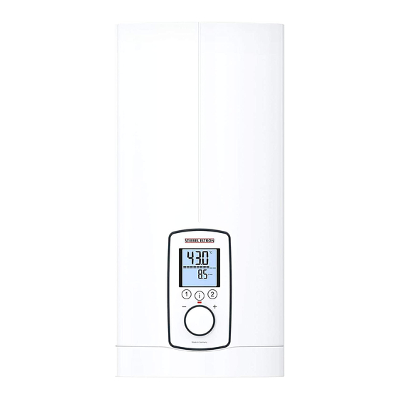
oPERATIoN Settings and displays Heating system Settings and displays The bare wire heating system is enclosed within a pressure-tested User interface plastic jacket. The heating system with its stainless steel heater spiral is suitable for hard and soft water areas and is largely in- susceptible to scale build-up. -
Page 10: Display Symbols ������������������������������������������������� 64 10. Installation
oPERATIoN Settings and displays Display symbols Selecting the set temperature The symbols are shown on the display when activated. 1 Wellness showers 2 Automatic water volume control 3 ECO display 4 Tmax, displayed when temperature limit is enabled 5 Consumption indicator 1 Set temperature settings: OFF, 20 - 60 °C 6 Time 2 To call up/assign preferred temperatures... -
Page 11: Temperature Limit Via Internal Anti-Scalding Protection (Qualified Contractor)
oPERATIoN Settings and displays Info menu When supplying a shower, the appliance temperature setting range must be adjusted by the qualified contractor to 55 °C or less. The appliance has an additional display where consumption values If the anti-scalding protection function is enabled and the tem- can be shown. -
Page 12: Settings In The Parameter Menu
oPERATIoN Settings and displays Settings in the parameter menu 4.9.1 Activating the parameter menu f Briefly press and hold "i" for more than 5 seconds until "P 1" appears, then continue by briefly pressing "i". f In the selected parameter menu, turn the temperature selec- tor to the required display / setting. - Page 13 oPERATIoN Settings and displays Menu Description Selectable display | Explanations Symbol | setting display P 3 Wellness showers OFF | Pro1 | Pro2 | Pro3 | The Wellness shower program lets you choose from 4 different alter- Pro4 nating shower programs. WW = domestic hot water, KW = cold water, min = minutes, sec = seconds - 1 Cold prevention To strengthen the body, we recommend finishing off with a cold...
- Page 14 oPERATIoN Settings and displays Menu Description Selectable display | Explanations Symbol | setting display P 4 Automatic water volume OFF | 5 | 10 | ... 200 l or With the automatic water volume control, you can preselect a volume control – set the volume 2 ...
- Page 15 oPERATIoN Settings and displays Menu Description Selectable display | Explanations Symbol | setting display P 12 Backlighting Auto | On You can adjust the display backlight. - If "Auto" is selected, the backlight is switched on during heating operation and each time an action is performed. If no action is per- formed for 30 seconds, the backlight is switched off again.
-
Page 16: Recommended Settings ��������������������������������������� 70 13.1 Electrical Connection From Above On Unfinished Walls
oPERATIoN Cleaning, care and maintenance 4.10 Recommended settings Following an interruption to the water supply Your instantaneous water heater offers maximum precision and Material losses maximum convenience in DHW provision. Should you nonetheless To ensure that the bare wire heating system is not dam- operate the appliance with a thermostatic valve, we recommend aged following an interruption to the water supply, the that you:... - Page 17 oPERATIoN Troubleshooting Troubleshooting If you cannot remedy the fault, contact your qualified contractor. To facilitate and speed up your enquiry, please provide the serial number from the type plate (000000-0000-000000). Problem Cause Remedy The appliance will not There is no power. Check the fuses / MCBs in start despite the DHW your fuse box / distribu-...
-
Page 18: Safety
INSTALLATIoN Safety INSTALLATIoN Shower operation CAUTION Burns f When supplying a shower, set the internal an- ti-scalding protection to 55 °C or less; see chapter Safety "Commissioning / Preparations". Only a qualified contractor should carry out installation, commis- sioning, maintenance and repair of the appliance. CAUTION Burns If operating with preheated water, e.g. - Page 19 INSTALLATIoN Appliance description Accessories - The electrical resistivity of the water must not fall below that stated on the type plate. In a linked water network, take into consideration the lowest electrical resistivity of the water. Wireless remote control Your water supply utility will advise you of the electrical re- - FFB 4 Set EU sistivity or conductivity of the water in your area.
-
Page 20: Preparation
INSTALLATIoN Preparation Pipe assembly for offset installation Preparation Use this pipe assembly if you intend to offset the appliance by up Installation site to 90 mm downwards from the water connection. Pipe assembly for replacing a gas water heater Material losses Install the appliance in a room that is free from the risk You will need this pipe assembly set if the existing installation of frost. - Page 21 INSTALLATIoN Preparation Oversink installation Minimum clearances ≥50 ≥50 1 Cold water inlet f Maintain the minimum clearances to ensure trouble-free op- 2 DHW outlet eration of the appliance and facilitate maintenance work. Note Water installation f Mount the appliance on the wall. The wall must have f Flush the water line thoroughly.
-
Page 22: Standard Installation
INSTALLATIoN Installation Permissible water line materials 10. Installation - Cold water inlet line: factory settings DHE 18/21/24 DHE 27 Pipes made from galvanised steel, stainless steel, copper or Internal anti-scalding protection °C plastic Connected load - DHW outlet line: Adjustable connected load... - Page 23 INSTALLATIoN Installation f Open the appliance by holding the fascia at the side and pull- Fitting the wall mounting bracket ing forwards away from the appliance cover. Undo the screw. Pivot open the appliance cover. f Mark out the holes for drilling using the installation tem- f Remove the back panel by pressing the two locking tabs and plate.
- Page 24 INSTALLATIoN Installation Material losses The strainer must be fitted for the appliance to function. f When replacing an appliance, check whether the strainer is installed. f Seal and insert the twin nipples. Installing the appliance Making the water connection Note If you are installing the appliance with flexible pipe con- nections, also secure the back panel with a screw.
- Page 25 INSTALLATIoN Installation f Pull the cable grommet over the cable sheath of the power f Lock the fixing toggle by turning it 90° clockwise. cable. For large cable cross-sections, enlarge the hole in the f Pull the cable grommets into the back panel until both lock- cable grommet if necessary.
- Page 26 INSTALLATIoN Installation Making the electrical connection Fitting the lower back panel section WARNING Electrocution Carry out all electrical connection and installation work in accordance with relevant regulations. WARNING Electrocution The connection to the power supply must be in the form of a permanent connection in conjunction with the re- 1 Diffuser on lower back panel movable cable grommet.
-
Page 27: Commissioning
INSTALLATIoN Commissioning 11. Commissioning CAUTION Burns If operating with preheated water, e.g. if using a solar 11.1 Preparation thermal system, the internal anti-scalding protection and the temperature limit Tmax, which can be set by the user, Internal anti-scalding protection via jumper slot may be exceeded. -
Page 28: Initial Start-Up
INSTALLATIoN Commissioning Changing the connected load via jumper slot; only with 11.2 Initial start-up DHE 18/21/24 If you select a connected load other than the 21 kW factory setting ≥ 60 s for appliances with selectable connected load, you will need to reposition the jumper. - Page 29 INSTALLATIoN Commissioning f Tick the selected connected load and rated voltage on the ap- pliance cover type plate (on both sides). Use a ballpoint pen to do this. f Secure the appliance cover with the screw. f Fit the fascia to the appliance cover. f Remove the protective film from the user interface.
-
Page 30: Recommissioning
INSTALLATIoN Appliance shutdown 11.3 Recommissioning 13. Installation alternatives Overview of installation alternatives Material losses To ensure that the bare wire heating system is not dam- Electrical connection IP rating aged following an interruption to the water supply, the On unfinished walls, connected from above IP 25 appliance must be recommissioned by taking the follow- On unfinished walls, connected from below, short... - Page 31 INSTALLATIoN Installation alternatives 13.1 Electrical connection from above on unfinished f Reposition the mains terminal from the bottom to the top. To do this, undo the fixing screw. Turn the mains terminal with walls connecting cables 180° clockwise. Route the cable around the cable guide when doing so.
-
Page 32: Electrical Connection On Unfinished Walls From Below With Short Power Cable
INSTALLATIoN Installation alternatives 13.2 Electrical connection on unfinished walls from below with short power cable 1 Cable grommet Electrical connection on finished walls Dimension A Positioned in lower section of appliance Positioned in upper section of appliance f Prepare the power cable. Fit the cable grommet. Material losses f Reposition the mains terminal further downwards. -
Page 33: Connecting A Load Shedding Relay
INSTALLATIoN Installation alternatives 13.4 Connecting a load shedding relay Install a load shedding relay in the distribution board in conjunc- 5 Nm tion with other electric appliances, e.g. electric storage heaters. The relay responds when the instantaneous water heater starts. 18 Nm Material losses Connect the phase that switches the load shedding relay to the indicated terminal of the mains terminal in the... -
Page 34: Water Installation On Finished Walls With Solder/Press
INSTALLATIoN Installation alternatives Note Observe the tap manufacturer's instructions. 13.7 Fitting appliance cover for water installation on 1 Tab finished walls 13.6 Water installation on finished walls with solder/press fittings Note This type of connection changes the IP rating of the ap- pliance. -
Page 35: Lower Back Panel Section Installation With Threaded Fittings On Finished Walls
INSTALLATIoN Installation alternatives Only if using the "solder fitting" accessory and with precise 13.8 Lower back panel section installation with adherence to all installation dimensions: threaded fittings on finished walls f Break the sealing lips out of the cover guides. f Position the back panel guides on the pipes. -
Page 36: Wall Mounting Bracket When Replacing An Appliance
INSTALLATIoN Installation alternatives 13.9 Wall mounting bracket when replacing an 13.10 Installation with offset tiles appliance An existing STIEBEL ELTRON wall mounting bracket may be used when replacing appliances (except the DHF instantaneous water heater), as long as the fixing screw is in the lower right position. Replacing a DHF instantaneous water heater 1 Minimum contact area of the appliance 2 Maximum tile offset... -
Page 37: Rotated Appliance Cover
INSTALLATIoN Installation alternatives 13.11 Rotated appliance cover WARNING Electrocution All 4 locking tabs on the programming unit must click into The appliance cover should be turned the other way up for un- place. The locking tabs must be complete and undam- dersink installation. -
Page 38: Horizontal Installation Of The Appliance
INSTALLATIoN Installation alternatives 13.13 Horizontal installation of the appliance Note For the horizontal installation alternative, please note the following points: - Installation is only permissible with direct wall mounting. The universal mounting frame cannot be 1 Cold water inlet used. 2 DHW outlet - The installation versions "Installation with offset tiles"... -
Page 39: Service Information
INSTALLATIoN Service information f Drill a hole from the outside through the dismantled appli- 14. Service information ance cover at the marked point. Alternatively, you can punch a hole in the appliance cover from the inside at the marked Overview of connections point. -
Page 40: Troubleshooting
INSTALLATIoN Troubleshooting Appliance cover retainer 15. Troubleshooting WARNING Electrocution To test the appliance, it must be connected to the power supply. Note When testing the appliance using the diagnostic traffic lights, water must be flowing. Signals of the diagnostic traffic lights (LED) Lights up in the event of a fault Yellow Illuminates in heating mode/flashes when output limit... - Page 41 INSTALLATIoN Troubleshooting Diagnostic traffic fault Cause Remedy lights (draw-off mode) No LED illuminates Appliance does not heat up One or more power supply phases are missing Check the fuses in the distribution board PCB faulty Replace the function module Green flashing, yellow No DHW Appliance starting flow rate not reached;...
-
Page 42: Fault Code Display
INSTALLATIoN Troubleshooting 15.1 Fault code display If there is an appliance fault, the spanner flashes on the display. f To call up the fault code display, press the "i" button for more than 5 seconds. Diagnostic traffic Display shown fault Cause Remedy lights (draw-off mode) -
Page 43: Maintenance
INSTALLATIoN Maintenance 16. Maintenance Clean strainer If the strainer in the threaded cold water fitting is dirty, clean it. WARNING Electrocution Close the 3-way ball shut-off valve or the shut-off valve in the Before any work on the appliance, disconnect all poles cold water inlet line before removing, cleaning and refitting the from the power supply. -
Page 44: Specification
INSTALLATIoN Specification 17. Specification Alternative connection options 17.1 Dimensions and connections ≤ 20 b02 Entry for electrical cables I Unfinished walls b03 Entry for electrical cables II Unfinished walls b04 Entry electrical cables III Finished walls b02 Entry for electrical cables I Unfinished walls Cold water inlet Male thread... -
Page 45: Wiring Diagram
INSTALLATIoN Specification 17.2 Wiring diagram Priority control with LR 1-A 3/PE ~ 380-415 V 1 Control cable to the contactor of the second appliance (e.g. electric storage heater) 2 Control contact drops out when switching the instantaneous water heater on. 1 Power PCB with integral safety switch 2 Bare wire heating system 3 High limit safety cut-out 4 Mains terminal... -
Page 46: Dhw Output
10 °C 15 °C 20 °C appliance's connected load and the cold water inlet temperature. The rated voltage and rated output can be found on the type plate. DHE 18/21/24 16.2 Connected load in kw 38 °C DHW output in l/min. 19.0 Rated voltage Cold water inlet temperature 21.7... -
Page 47: Pressure Drop
Sizing the pipework When calculating the size of the pipework, an appliance pressure drop of 0.1 MPa is recommended. 17.7 Energy consumption data Product datasheet: Conventional water heaters to regulation (EU) no. 812/2013 | 814/2013 DHE 18/21/24 DHE 27 202656 202657 Manufacturer... -
Page 48: Data Table
INSTALLATIoN Specification 17.8 Data table DHE 18/21/24 DHE 27 202656 202657 Electrical data Rated voltage Rated output 16.2/19/21.7 18/21/24 19.4/22.6/25.8 24.4 Rated current 27.6/29.5/33.3 29/31/35 30.1/32.2/36.3 37.1 Fuse protection 32/32/35 32/32/35 32/32/40 Frequency 50/60 50/60 50/- 50/- 50/- Phases 3/PE 3/PE Resistivity ρ15 ≥... - Page 49 INSTALLATIoN Specification DHE 18/21/24 DHE 27 Versions Adjustable connected load Temperature settings °C Off, 20-60 Off, 20-60 Protection class Insulating block Plastic Plastic Heating system heat generator Bare wire Bare wire Cover and back panel Plastic Plastic Colour White White IP rating IP 25...
- Page 50 GUARANTEE | ENVIRONMENT AND RECYCLING Guarantee The guarantee conditions of our German companies do not apply to appliances acquired outside of Germany. In countries where our subsidiaries sell our products a guarantee can only be issued by those subsidiaries. Such guarantee is only grant- ed if the subsidiary has issued its own terms of guarantee.
- Page 51 Deutschland Verkauf Tel. 05531 702-110 | Fax 05531 702-95108 | info-center@stiebel-eltron.de Kundendienst STIEBEL ELTRON GmbH & Co. KG Tel. 05531 702-111 | Fax 05531 702-95890 | kundendienst@stiebel-eltron.de Dr.-Stiebel-Straße 33 | 37603 Holzminden Ersatzteilverkauf Tel. 05531 702-120 | Fax 05531 702-95335 | ersatzteile@stiebel-eltron.de Tel.
Need help?
Do you have a question about the DHE 18 and is the answer not in the manual?
Questions and answers