Makita DFR452 Instruction Manual
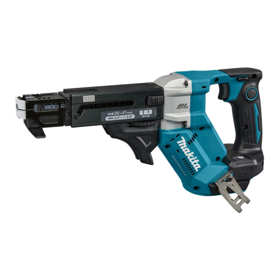
Cordless auto feed screwdriver
Hide thumbs
Also See for DFR452:
- Instruction manual (81 pages) ,
- Instruction manual (16 pages) ,
- Instruction manual (41 pages)
Table of Contents
Advertisement
Quick Links
Advertisement
Table of Contents

Related Manuals for Makita DFR452


Summary of Contents for Makita DFR452
- Page 1 INSTRUCTION MANUAL Cordless Auto Feed Screwdriver DFR452 DFR551 Read before use.
-
Page 2: Specifications
Only use the battery cartridges and chargers listed above. Use of any other battery cartridges and chargers may cause injury and/or fire. Symbols Noise The followings show the symbols which may be used The typical A-weighted noise level determined accord- for the equipment. Be sure that you understand their ing to EN62841-2-2: meaning before use. Model DFR452 Sound pressure level (L ) : 75 dB(A) Read instruction manual. Uncertainty (K) : 3 dB(A) Model DFR551 Sound pressure level (L ) : 74 dB(A) Only for EU countries... -
Page 3: Ec Declaration Of Conformity
The vibration total value (tri-axial vector sum) deter- adapter plugs with earthed (grounded) power mined according to EN62841-2-2: tools. Unmodified plugs and matching outlets will Model DFR452 reduce risk of electric shock. Work mode: screwdriving without impact Avoid body contact with earthed or grounded Vibration emission (a ) : 2.5 m/s... -
Page 4: Cordless Screwdriver Safety Warnings
Do not let familiarity gained from frequent use Keep handles and grasping surfaces dry, clean of tools allow you to become complacent and and free from oil and grease. Slippery handles and ignore tool safety principles. A careless action can grasping surfaces do not allow for safe handling and cause severe injury within a fraction of a second. - Page 5 It may result in loss of your eyesight. CAUTION: Do not short the battery cartridge: Only use genuine Makita batteries. Use of non-genuine Makita batteries, or batteries that Do not touch the terminals with any con- have been altered, may result in the battery bursting ductive material. causing fires, personal injury and damage. It will...
-
Page 6: Functional Description
Tool / battery protection system FUNCTIONAL DESCRIPTION The tool is equipped with a tool/battery protection sys- tem. This system automatically cuts off power to the motor to extend tool and battery life. The tool will auto- CAUTION: matically stop during operation if the tool or battery is Always be sure that the tool is placed under one of the following conditions: switched off and the battery cartridge is removed before adjusting or checking function on the tool. Overload protection Installing or removing battery When the tool/battery is operated in a manner that... - Page 7 Indicating the remaining battery Setting for desired screw lengths capacity For model DFR452 The tool provides 4 positive-lock screw length settings. Only for battery cartridges with the indicator Slide the stopper base out and in while depressing the levers on the top surface of the stopper base so the number for desired screw length (indicated on the label) appears in the reading window.
- Page 8 Switch action Numbers indicated on Screw length ranges the label 25 mm (1″) WARNING: Before installing the battery car- 25 mm - 30 mm (1″ - 1-3/16″) tridge into the tool, always check to see that the switch trigger actuates properly and returns to 30 mm - 35 mm (1-3/16″ - 1-3/8″) the "OFF" position when released. 35 mm - 40 mm (1-3/8″ - 1-9/16″) To start the tool, pull the switch trigger.
- Page 9 Press and hold the release buttons on each side Push drive mode of the casing, and then pull the casing apart. In push drive mode, the driver bit only rotates by apply- ing pressure onto the driving surface with the stopper base, allowing the tool to cut off power to the motor to save battery power at idle. To select push drive mode, pull the switch trigger slightly, then release it and quickly press the mode select button.
-
Page 10: Installing Hook
Installing screw strip Removing screw strip Insert a screw strip through the screw strip guide on To remove the screw strip, pull it upwards out of the feeder box. the casing, and then insert it through the screw loading guide in the feeder box. Fig.14 The screw strip can be pulled downwards out of the feeder box while pressing the reverse button on the feeder box. -
Page 11: Driving Operation
Driving operation in push drive OPERATION mode Driving operation Pull the switch trigger slightly and release it. Then quickly press the mode select button. NOTICE: Always check the driver bit carefully The indicator lamp on the push drive mode selector for wear before driving operations. Replace a worn lights up, and push drive mode becomes activated. driver bit or poor fastening may result. - Page 12 Press and hold the release buttons on each side Driving in corner of the casing, and then pull the casing apart. CAUTION: Driving at a position closer than 15 mm to the wall or driving with the stopper base in contact with the wall may damage the screw heads and cause wear on the driver bit. This may also lead to poor fastening of screws and malfunction of the tool.
-
Page 13: Maintenance
Centers, always using Makita replacement parts. After use Wipe off the tool using a dry cloth or cloth slightly moist- ened with soapy water at regular intervals. OPTIONAL ACCESSORIES CAUTION: These accessories or attachments are recommended for use with your Makita tool specified in this manual. The use of any other accessories or attachments might present a risk of injury to persons. Only use accessory or attachment for its stated purpose. If you need any assistance for more details regard- ing these accessories, ask your local Makita Service Center. - Page 16 Makita Europe N.V. Jan-Baptist Vinkstraat 2, 3070 Kortenberg, Belgium Makita Corporation 3-11-8, Sumiyoshi-cho, Anjo, Aichi 446-8502 Japan 885905-229 www.makita.com 20210604...
Need help?
Do you have a question about the DFR452 and is the answer not in the manual?
Questions and answers