
Subscribe to Our Youtube Channel
Related Manuals for VocoPro Digital-1


Summary of Contents for VocoPro Digital-1
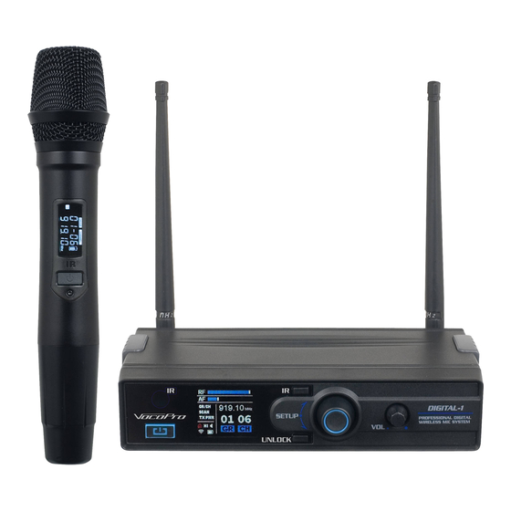
- Page 1 Digital-1 Digital Wireless Microphone with Mic-On-Chip Technology ’...
-
Page 3: Table Of Contents
TABLE OF CONTENTS Safety . . . . . . . . . . . . . . . . . . . . . . . . . . . . . . . . . . 4 FCC Information . -
Page 4: Safety
SAFETY 8. Ventilation - The appliance should be situated so its CAUTION location does not interfere with its proper ventilation. For example, the appliance should not be situated on a bed, sofa, rug, or similar surface that may block the RISK OF SHOCK ventilation slots. -
Page 5: Fcc Information
1. To ensure the finest performance, please read this requirements. Modifications not expressly approved by manual carefully. Keep it in a safe place for future Vocopro may void your authority, granted by the FCC, reference. to use this product. 2. Install your unit in a cool, dry, clean place - away from 2. -
Page 6: Welcome
And while you're there don't forget to check out our Club VocoPro for Karaoke news and events, chat rooms, club directories and even a KJ Service directory! We look forward to hearing you sound like a PRO, with VocoPro, the singer’s ultimate choice. FOR YOUR RECORDS Please record the model number and serial number below, for easy reference, in case of loss or theft. -
Page 7: Listening
Now it’s time to consider how you can maximize the fun and excitement your equipment offers. VocoPro and the Electronic Industries Association’s Consumer Electronics Group want you to get the most out of your equipment by playing it at a safe level. One that lets the sound come through loud and clear without annoying blaring or distortion and, most importantly, without affecting your sensitive hearing. -
Page 8: Specifications
Frequency Switch: IR SYNC Output Power: 0 .40 mW Harmonic Radiation: <-50 dBc Battery: 1x18500 Lithium Battery Life: >8h WHAT’S IN THE BOX: Power Adapter 1/8” - 1/8” stereo cable Lithium Battery (18500) USB Charge Cable Digital-1 Reciever Digital-1 Microphone... -
Page 9: Getting Connected
AV1 INPUT HEADPHONES • Connect one end of the ¼” cable into the Mixed Output jack located on the back of the Digital-1 receiver . • Connect the other end of the ¼” cable into a unbalanced microphone input jack on the mixer or sound system being used . -
Page 10: Descriptions And Functions
DESCRIPTIONS AND FUNCTIONS FRONT PANEL - RECEIVER 1 . IR Sensor – This is used to pair and sync the microphone . 2 . IR Button – This is used to initialize the pairing mode . 3 . Selector Knob – This navigates the menu and is used to confirm a selection . Click knob to confirm selection . - Page 11 DESCRIPTIONS AND FUNCTIONS BACK PANEL – RECEIVER USB CHARGE OUTP U T 1 . Antenna – These receive the RF/AF transmission from the microphone . 2 . Mixed Output – This unbalanced ¼” output sends the microphone audio out to a mixer or sound system .
- Page 12 DESCRIPTIONS AND FUNCTIONS MICROPHONE 1 . Display – This shows current frequency, battery level, and transmission level . a . Display Icons • – Indicates microphone battery level. The indicator will GROUP CHANNEL display remaining battery power . 01-06 • Mute – This is the microphones mute status. When lit, the microphone audio is muted .
-
Page 13: Operations
OPERATIONS CHANGING THE FREQUENCY: The Digital-1 utilizes a frequency analyzer to provide a graphical view of the environmental interference . The color LCD screen will display a graph of the current interference . Once identified, the frequency can be changed automatically or manually . - Page 14 OPERATIONS MANUALLY: 919.10 GR/CH 01 06 SCAN TX PWR 1 . Press and hold the unlock button the access the Menu . 2 . Highlight and select the “GR/CH” option with the Selector Knob . 3 . Select from either “GR” or “CH” to modify the channel . a .
- Page 15 CHANGING THE TRANSMISSION POWER The Digital-1 has two levels of output transmission: high and low . The Low setting has a range of over 100ft . The High setting has a range of over 200ft but consumes the battery at a faster rate .
-
Page 16: Commonly Asked Questions
1. WHY IS THERE NO MICROPHONE AUDIO? • The mic volume is turned down. • The connections from the Digital-1 recever and the sound system are disconnected. • The microphone needs to be resynced with the receiver. Refer to “changing the frequency”. - Page 17 FCC Caution. § 15.19 Labelling requirements. This device complies with part 15 of the FCC Rules. Operation is subject to the following two conditions: (1) This device may not cause harmful interference, and (2) this device must accept any interference received, including interference that may cause undesired operation.
Need help?
Do you have a question about the Digital-1 and is the answer not in the manual?
Questions and answers