
Related Manuals for Viewpro Q30T pro


Summary of Contents for Viewpro Q30T pro
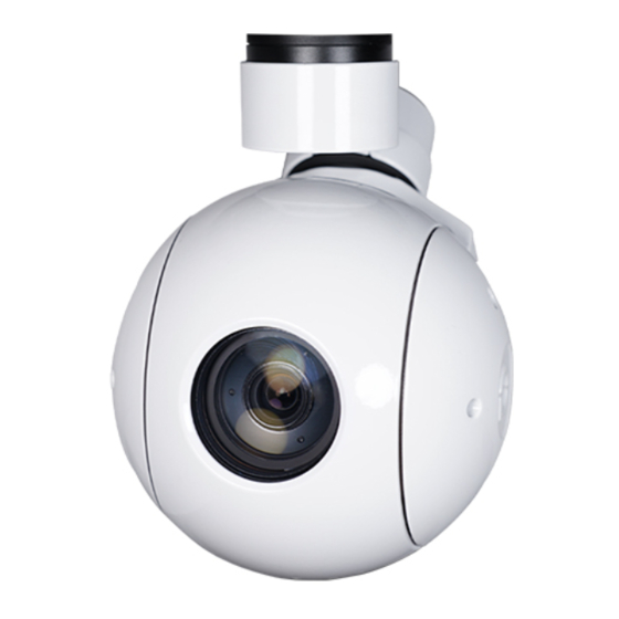
- Page 1 Q30T pro 30x Optical Zoom Object Tracking Gimbal Camera User Manual Standard Version Viewport Version 标准版 快拆版 For more details please scan the QR code or visit our website: www.viewprotech.com...
-
Page 2: Disclaimer And Warning
3 axis gimbal can achieve stabilization in yaw, roll and pitch. The integrated design of damping system and gimbal can greatly reduce mechanical vibration. Q30T pro is widely used in UAV industries of public security, electric power, fire fighting, zoom aerial photography and other industrial applications. -
Page 3: Standard Version
1.2 In the Box A. Standard Version Gimbal Camera USB to TTL Cable x 1 pc x 1 pc Copper Cylinder M3 Screw x 4 pcs x 8 pcs Power Cable x 1 pc B. Viewport Version Gimbal Camera USB to TTL Cable x 1 pc x 1 pc Copper Cylinder... -
Page 4: Installation Instruction
TTL / S.BUS Control Cable x 1 pc TTL Connect Cable x 3 pcs Ethernet Cable x 1 pc 2. Installation Instruction 2.1 Overview [10] [12] [11] Control Box Back Side (Standard Version) [10] [13] [12] Viewport [11] (Viewport Version) - Page 5 [8] Roll axis motor [1] Control box [9] Pitch axis motor [2] Upper damping board [10] 3-6S power interface [3] Lower damping board [11] Micro HDMI interface [4] FHD zoom camera [12] Ethernet interface [5] Damping ball [6] Yaw axis motor [13] Viewport unlock button [7] TF card slot Please ensure that there isn’t any obstacle while the...
- Page 6 2.2.2 Control Box Printing (Viewport Version) Front Side POWER Left Side ETHERNET UART & S.BUS Right Side...
- Page 7 2.3 Device Dimensions (Standard Version) Unit: mm 62.2 103.5 128.9...
- Page 8 2.3 Device Dimensions (Viewport Version) Unit: mm 40.3 41.6 Control Box 72.4 103.5 128.9 121.5...
- Page 9 2.4 Install Mounting Part (1) Find out the arrow on the gimbal which indicating the yaw heading of the payload (i.e. the lens direction when the camera power on), and synchronize with the direction specified by the UAV. (2) Fix one end of the copper cylinder on the screw hole of lower damping board, and use M3 screw to fasten it.
- Page 10 2.5 Viewport Release Instruction × 1. Make sure the two white stripes indicated in above picture are aligned with each other. (If the stripes are not aligned to each other, please pinch the connector part and turn it to left manually)
- Page 11 2. Align the white dot (unlock icon) to the red triangle (below unlock button), push the gimbal into the Viewport completely and then rotate the gimbal camera anticlockwise. 3. When you hear "click" sound (when red dot is aligned to the red triangle) means the gimbal camera and Viewport has been locked.
- Page 12 2.6 Install TF Card TF (Micro SD card): Install the TF card to the card slot (Re. 2.1 Overview). Support max 128GB. Request Class 10 (10m/s) transmis- sion speed or higher and FAT32 or exFAT format. Make sure device is power off when inserting the TF card, hot plugging is not supported.
-
Page 13: Signal Control
Above output mode is optional, HDMI and SDI output cannot coexist at the same time. Please subject to your actual product. When using user interface software Viewlink for network connection, the network of external device (computer) should be the IP address: 192.168.2.2 (choose the last byte among 2~254, can not be 119 same as the gimbal), subnet mask: 255.255.255.0, Default gateway: 192.168.2.1, and all firewalls of the... - Page 14 PWM IN 5V OUTPUT Remote Controller Receiver Connection Diagram (Standard Version) Receiver Remote Controller Connection Diagram (Viewport Version)
- Page 15 3.1.2 PWM Control Operation Instruction 1) Pitch (PWM Pitch channel in to control Pitch. Joystick, rotary knob or 3-gear switch on remote control are optional. 3-gear switch as example.) Position 1 Position 2 Position 3 Low Gear Middle Gear High Gear Pitch Up Pitch Stop Pitch Down...
- Page 16 Position 1 Position 2 Position 3 Low Gear Middle Gear High Gear Position 1: Low speed mode, control pitch / yaw with this mode at lowest speed Position 2: Middle speed mode, control pitch / yaw with this mode at middle speed Position 3: High speed mode, control pitch / yaw with this mode at highest speed...
- Page 17 4) Zoom (PWM Zoom channel in to control Zoom. Joystick, rotary knob or 3-gear switch on remote control are optional. 3-gear switch as example.) Position 1 Position 2 Position 3 Low Gear Middle Gear High Gear Zoom Out Stop Zoom Zoom In 5) Focus ( not functional for this channel) 6) Pic/Rec (PWM Pic/Rec channel in to control take picture and...
- Page 18 7) Multi: Tracking control Position 1 Position 2 Position 3 Low Gear Middle Gear High Gear Switch from Position 2 to 1: Cancel tracking Switch from Position 2 to 3: Exit the tracking, display the lock frame in the center of the screen, start tracking Switch from Position 3 to 2: "+"...
- Page 19 USB to TTL Cable Control Box Connection Diagram Standard Version USB to TTL Cable Viewport Control Box Connection Diagram Viewport Version...
-
Page 20: S.bus Control
TTL control protocol file. ViewLink is a user interface developed by Viewpro for Viewpro gimbal cameras, you can download it from Viewpro website (www.viewpro- tech.com) or ask distributors for installation package. - Page 21 5V OUTPUT Remote Control Receiver Wiring Diagram Standard Version Receiver Remote Control Wiring Diagram Viewport Version...
- Page 22 (please contact with our technical support for the setting instruction.) 3.4 TCP control For Viewpro gimbal cameras with Ethernet output, the default IP address is: 192.168.2.119, control port: 2000. You can send the corresponding protocol to realize TCP control after connecting.
-
Page 23: Specification
4. Specification Hardware Parameter Working voltage Input voltage 3S ~ 6S Output voltage 5V (connect with PWM) Dynamic current 650mA @ 12V Idle current 550mA @ 12V Working environment -20℃ ~ +60℃ temp micro HDMI(1080P 60fps) / Output IP (720p) / SDI (1080P 30fps) SD card (Up to 128G,class 10, Local-storage FAT32 or ex FAT format) - Page 24 Pitch/Tilt: -45°~90°, Angle range of Yaw/Pan: ±290° / ±360°*N software design (IP / SDI output version) Vibration angle Pitch/Roll: ±0.02°, Yaw:±0.02° One-key to center √ Camera spec Imager Sensor SONY 1/2.8" "Exmor R" CMOS Picture quality Full HD 1080 (1920*1080) Effective pixel 2.13MP Photo storage format JPG(1920*1080)
- Page 25 Min illumination Color 0.01lux@F1.6 Auto, Manual, Priority mode (shutter priority & iris priority), Exposure control Bright, EV compensation, Slow AE Auto/Manual 0dB to 50.0dB (0 to 28 steps + 2 setep/ total 15 steps) Gain Max.Gain Limit 10.7 dB to 50.0dB (6 to 28 steps + 2 step/ total 12 steps) Auto, ATW, Indoor, Outdoor, One Push WB, Manual WB, Outdoor Auto, Sodium Vapor...
- Page 26 Minimum object 32*32 pixel size Maximum object 128*128 pixel size Tracking speed 32 pixel/frame Object memory time 100 frames (4s) The mean square root values of pulse < 0.5 pixel noise in the object position Packing Information N.W. 876g Product meas. 121.5*166.5*130mm 1pc gimbal camera device, screws, copper cylinders, damping balls, damping boards /...
- Page 27 5. FAQ 1. How to deal with whitening visible image of Q30T pro in foggy weather? A: Enable defogging mode 2. Does Q30T pro support taking photos during recording? A: Yes 3. How to set the storage format of Q30T pro ? A: When the IP output resolution is set to 1280*720, the storage resolution is 1920 * 1080;...
Need help?
Do you have a question about the Q30T pro and is the answer not in the manual?
Questions and answers