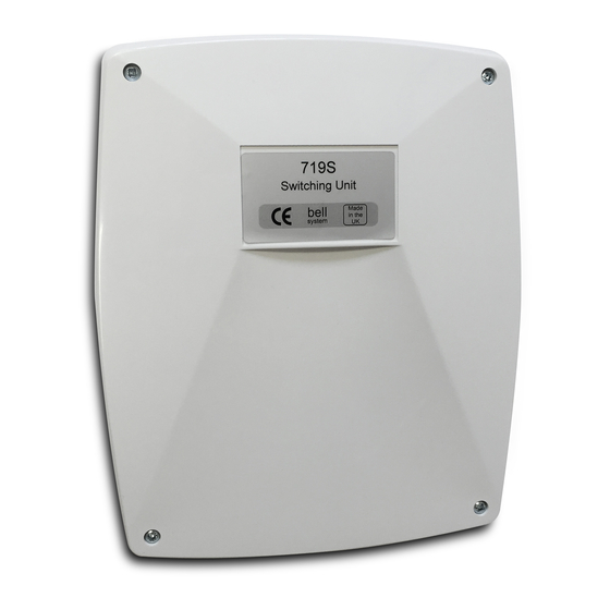
Summary of Contents for Bell System 719S
- Page 1 Bell System (Telephones) Ltd Model 719S 2 Door Switching Unit PD-008 Iss 6 PD-008 Iss 6 Installation & Operation Manual 12/08/2008...
-
Page 2: Table Of Contents
719S 2 Door Switching Unit Table of Contents GENERAL DESCRIPTION ..................3 ......................3 PERATION ......................3 ELEPHONES ......................3 OWER UPPLY ................ 4 LECTRIC ELEASE AGLOCK ...................... 4 GRESS ACILITY ....................4 RADESMAN ACILITY ..................4 TATUS NDICATION ................4... -
Page 3: General Description
Power Supply The 719S is powered from a 12V AC 2A PSU (225) for AC telephones or 12V DC 4A PSU (PS4) for DC telephones. A separate power supply is required for each 719S unit in multi-door systems (see Diagrams 2 or 4). -
Page 4: Electric Lock Release / Maglock
Systems With 3 or More Doors One 719S unit is required for every two doors up to a maximum of 16 doors (e.g. 5 doors requires 3 x 719S units). Refer to diagram 2 (AC telephone models) or diagram 4 (DC telephone models). -
Page 5: Settings
719S 2 Door Switching Unit see to document PD-082). Settings Speech Active Time The duration for which speech remains active (from the moment a telephone is called) can be set between 30 and 120 seconds using the PCB DIP switch marked >SW2': Time (s) ‘SW2’... -
Page 6: Important Safety Information
719S 2 Door Switching Unit Important Safety Information Connections to the 240V AC mains supply must be carried out by a qualified electrician or similar competent person, and made in accordance with accepted safety practices. A two-pole switch (as provided by a Consumer Unit or Switch-Fuse) must be included to isolate both Live and Neutral during Installation or Maintenance. -
Page 7: Installation
719S 2 Door Switching Unit Installation Initially connect all the equipment to one telephone ONLY. With the power applied, test the system is fully operational. Connect one telephone at a time and test before proceeding. PD-008 Iss 6 Installation & Operation Manual... -
Page 8: Cable Requirements
719S 2 Door Switching Unit Cable Requirements Use standard 0.5mm solid core twisted-pair CAT5/CAT5e unshielded or CW1308 telephone cable for all connections unless otherwise specified. Do not use stranded alarm cable. For optimum speech clarity a twisted-pair must be used for the 'R' and 'O' connections to telephone and speech unit. -
Page 9: Troubleshooting
LED Status Indicators To assist in testing and fault diagnosis there are 4 LED Indicators on the 719S PCB which can be interpreted as follows: - LED 1 (GREEN) - Page 10 Faulty 'O' or 'I' line between Switching Unit Telephone will not buzz (no green LED illuminated and phone. ‘B’ terminal on the 719S not wired to the call on the 719S) button commons in the entrance panel (only if no ringing on several phones). Check for 12V on the ‘B’...
- Page 11 Lock button stuck down. Disconnect the ‘Z’ Lock operates as soon as called, short talk time. wire (lock button) from the 719S and check. 'Z' and 'O' lines permanently shorted together. Disconnect the ‘Z’ wire from the 719S and check.
-
Page 12: Technical Specification
719S 2 Door Switching Unit Technical Specification Size Boxed 238mm x 189mm x 50mm Size PCB Only 177mm x 137mm x 18mm Supply Voltage 11.5V - 15Vrms 50Hz AC or 11.5V - 15V DC Current Consumption 590mA maximum AC or... -
Page 13: Diagram 1: Wiring For 2 Door Ac Systems
719S 2 Door Switching Unit Diagram 1: Wiring for 2 Door AC Systems PD-008 Iss 6 Installation & Operation Manual Page 13 of 20... -
Page 14: Diagram 2: 719S Ac Interconnections For Systems Of 3 - 16 Doors
719S 2 Door Switching Unit Diagram 2: 719S AC Interconnections For Systems Of 3 – 16 Doors PD-008 Iss 6 Installation & Operation Manual Page 14 of 20... -
Page 15: Diagram 3: Wiring Diagram For 2 Door Dc Systems
719S 2 Door Switching Unit Diagram 3: Wiring Diagram for 2 Door DC Systems PD-008 Iss 6 Installation & Operation Manual Page 15 of 20... -
Page 16: Diagram 4: 719S Dc Interconnections For Systems Of 3 - 16 Doors
719S 2 Door Switching Unit Diagram 4: 719S DC Interconnections For Systems Of 3 – 16 Doors PD-008 Iss 6 Installation & Operation Manual Page 16 of 20... -
Page 17: Diagram 5: Distribution Of Common Cables Of Bs-Lx Phones
719S 2 Door Switching Unit Diagram 5: Distribution of Common Cables of BS-LX Phones PD-008 Iss 6 Installation & Operation Manual Page 17 of 20... -
Page 18: Bs-Lx Phones
719S 2 Door Switching Unit Diagram 6: Connection Of Additional PSU for 21-60 BS-LX Phones PD-008 Iss 6 Installation & Operation Manual Page 18 of 20... -
Page 19: Diagram 7: Door Contact / Switch Wiring
719S 2 Door Switching Unit Diagram 7: Door Contact / Switch Wiring PD-008 Iss 6 Installation & Operation Manual Page 19 of 20... -
Page 20: Manufacturer Details
719S 2 Door Switching Unit Manufacturer Details Bell System (Telephones) Ltd. Presley Way, Crown Hill, Milton Keynes MK8 0ET. Tel: 01908 261106 (Sales and Technical Support) FAX: 01908 261116 Local rate numbers Tel: 0845 121 4008 (Sales and Technical Support)


Need help?
Do you have a question about the 719S and is the answer not in the manual?
Questions and answers