Table of Contents
Advertisement
Advertisement
Table of Contents

Related Manuals for Baxi MULTI-HEAT


Summary of Contents for Baxi MULTI-HEAT
- Page 1 EN/137466/0/14-06-2002 INSTRUCTIONS MULTI-HEAT INSTRUCTION FOR INSTALLATION AND USE OF BAXI MULTI-HEAT List of sections Section Operating and owner instructions Possibilities for automation Installation instructions Technical data and wiring diagram Setup and test report...
- Page 2 It is hereby declared that below BAXI product: Multi-Heat complies with the EEC directives mentioned below.
-
Page 3: Table Of Contents
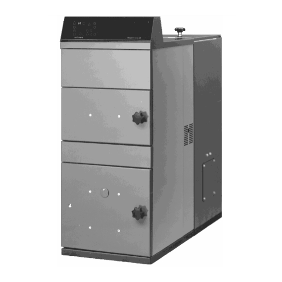
93/68/EEC Directive 98/37/EEC of the European Parliament and of the Council of 22 June 1998 on the approximation of the laws of the Member States relating to machinery The photograph shows MULTI-HEAT 2.5 Page 1 List of contents... -
Page 4: Use And The User's Task / Responsibility / Possibilities
5 GENERAL DELIVERY SURVEY REPORT FOR BOILER SYSTEM 5.1 MEASURED AND ADJUSTED VALUES Due reservations are made regarding construction amendments and possible printing errors. Page 2 1 Use and the user's task / responsibility / possibilities 1.1 Overview of the boiler and the equipment Control Panel... - Page 5 Cleaning door, top Combustion chamber Burner Cleaning door, bottom Observation flap Air apertures for the combustion Blow-off faucet (on type 2.5 this is placed between the fire box and the hopper) Delivery screw for air chamber (on type 2.5 this is placed directly over the bottom frame on the right-hand side.
- Page 6 Page 3 1.1.1 Fuel forms (see also page 1) Wood pellets MULTI-HEAT is delivered as a standard for firing with wood pellets. MULTI-HEAT 1.5 is principally designed for wood pellets. The wood pellets must be pure wood. 1. Without additives or chemical or synthetic binders 2.
- Page 7 ÷ = must not be used Usage of other and less suitable fuel types for MULTI-HEAT - over and above the wood pellets indicated above, grain (wheat and barley), corn (maize) as well as wood chips can result in less problem-free operation, more work for the user and possibly a greater fuel consumption.
-
Page 8: Responsibility And Safety
1.1.3 Service and guarantees: The guarantee is described more closely in the BAXI Guarantee Certificate which is delivered together with the boiler. Complaints: You ought always refer to the fitter or dealer who has installed / delivered the central heating boiler for you. -
Page 9: Description Of Operation
It is the responsibility of the owner or user that the boiler and equipment, if any, are cleaned and maintained in accordance with: normal practice indications in this instruction instructions for equipment / accessories, if any as well as conditions described in the appurtenant guarantee certificate (See section 1.18 Preventive maintenance as well as the boiler's guarantee certificate). - Page 10 Form of operation Ebullition thermostat ON / OFF button - ignite / extinguish Error! Unknown switch argument. Alarm reset - cancel alarm Manual worm conveyor/auger - forwards Manual worm conveyor/auger - backwards Light diodes Set = boiler temperature. High output Low output Firing at intervals Pump...
- Page 11 (E) Ignite takes place by pressing the ON/OFF button (E) and this will be displayed in the light diode above the button.. (J) Boiler temp. is adjusted by keeping set (J) pressed in and simultaneously pressing on + or – on REG (R).
- Page 12 • Supply pipe boiler temperature. temperature • Return temperature return temperature to the boiler • Set temperature the set, desired boiler temperature • Smoke temperature the temperature in the boiler's fire tubes (Symbols for 02% and the ventilator's actual % only apply for the model with oxygen control.
- Page 13 Fixed low output light above button and light on row 30-100% The greatest advantage can be achieved by choosing the form of operation called 2- step operation.. 2-step operation: Here, the boiler must run at a high output until the temperature is just 3 degrees below the desired temperature, and then switched down to a low output.
- Page 14 The lowest button is used to set the number of seconds between each worm conveyor/ auger delivery - this can be set between 10 and 60 seconds, but never below the setting of the high output. The setting is shown in the display. Press in and hold "SEC" and adjust up or down by means of pressing on + or –.
- Page 15 (F) Alarm re-set- Here, the alarm is re-set. If there is no alarm, use the button to come into the set-up menu (but simultaneously with the (C)-button). The following are the alarms which can appear: There is no fire! The smoke temperature has been below 100°C during operation for more than 30 minutes of operation, or after intermittent firing and starting up.
- Page 16 (LX.X) Here, the worm conveyor/auger's adjustment time is adjusted at "low output" - i.e. the time which the worm conveyor/auger is running each time. Adjustment area: 0.1-6.0, corresponding to 0.1-6.0 seconds. Factory setting:: MULTI-HEAT HX.X LX.X Type (high output) (low output) H1,7 = 1,7 sec.
-
Page 17: Starting Up The Boiler
Factory setting (P05) = 5 seconds The settings can be changed by pressing on + or minus on REG (R). By means of the operation form button (C), the desired setting can be saved, and it is possible to "step" further in the menu. Step through the program with the menu button (B). -
Page 18: Ignition
Prior to starting up the boiler, it is necessary to ensure that the water supply is connected to the retrograde combustion (back burn) valve. (See section 1.16 - retrograde combustion (back burn) valve). It is necessary to ensure that the ignition/fuel arc (pos. 9, fig. 1.1) is pushed right back. The hopper lid must be closed, since this hinders retrograde combustion (back burn). -
Page 19: Extinguishing
80-160 W/m2 and in a more modern house, approx. 50 W/m After this, set at low output - see technical data and use the recommended adjustment data from the PC- diskette from BAXI A/S. The colour of the flame ought to be yellow and slightly bluish. -
Page 20: User Experiences
If the flame is short and blue, either the interval time or the air quantity must be reduced. If the flame is long and reddish-yellow, either the interval time or the air quantity must be reduced. Colour of the flue gas If the flue gas is black or dark-coloured, this is because the combustion is getting insufficient air. - Page 21 Type Output Sec. Sec. Sec. Sec. Min. step Adjustment for firing with wood pellets and grain – (moisture content see point 1.1.1) (MULTI-HEAT 1.5 only wood pellets): High 1,5* Pause High 0,3* Pause High 0,5* Pause...
- Page 22 Adjustment of operation for corn (maize) - moisture content see point 1.1.1 High Pause High Pause Adjustment of operation for wood chips (fine chips) - moisture content see point 1.1.1 High 2,5* 11,7 1,5* 1,5* 1,5* Pause High 4,0* 18,9 2,5* 2,5*...
-
Page 23: Cleaning The Boiler
4. Cleaning the fire tubes On MULTI-HEAT 1.5 and 4.0, turn the smoke gas turbolators approx. 15 times so that the ash particles are sucked backwards into the smoke box. -
Page 24: Operating The Pump
5. Removing cinders Removing cinders from the boilers combustion chamber takes place as required. This requirement is dependent on the ash contents of the fuel. 6. Cleaning the vent pipe While cleaning the vent pipe from the boiler to the chimney, it is important NB: the smoke gas sensor is that the smoke gas sensor is meanwhile removed so that is does not get bent removed. -
Page 25: Safety Sprinkler Device
Page 13 1.16 Safety sprinkler device Valve type SYR (fixed setting) safety sprinkler device. The safety sprinkler device is fitted and adjusted by the factory and the heating and ventilation fitter will have fitted this to thr domestic water suply. If the temperature on the outside of the worm conveyor pipe exceeds 95°C, the valve vil be activated and water will be allowed to enter. - Page 26 See under point Error A1 (there is no fire 1, 6, 7, 8, and 9 Error A2 (ebullition thermostat) 4 and 10 Error A3 (motor protection) 4 and 11 Error A4 (flow temperature >94°C The fuel is not conveyed forwards 1, 2, 3, 4, 6, 9 and 11 The backfire safety sprinkler has been released 1, 5 and 11...
-
Page 27: Preventive Maintenance
2.0 bar). For best boiler function, operating economy and boiler life, we recommend taking out a service contract with a competent service company authorised by BAXI for annual inspection and servicing of the boiler. 1.19 Summer stop The boiler must be thoroughly cleaned if it is stopped completely in summer. -
Page 28: Installation Instructions
The regulator for the weather compensation system can be mounted in the boiler control system on MULTI-HEAT 2.5 and 4.0 (but not on MULTI-HEAT 1.5). Electrical connection is traditionally carried out without a Multi-plug, by means of the bottom-side's terminal strips. -
Page 29: Chimney Connection
Please consult your chimney sweep before building in a draft stabiliser. A draft stabiliser can be bought from BAXI as an accessory (see figure below – secure draft stabiliser in appropriate material with external bearings with good accuracy of adjustment). -
Page 30: Expansion, Safety Valves And Pump Connection
BAXI draft stabiliser: Fitted on boiler flue, BAXI-no. 082330 2+3) Built into chimney, BAXI-no. 291657 Draft stabiliser on vertical chimney Draft stabiliser on horizontal chimney 3.4 Expansion, safety valves and pump connection 3.4.1 Expansion tank... - Page 31 The size of the expansion tank is determined on the basis of the total water contents in the heating system. Open expansionstank: App. 8% of total water content of the heating system. The open expansion tank can be replaced with a closed expansion tank. Insofar as a system has been established with a closed expansion tank, manual stoking of the boiler is not permitted 3.4.2 Thermal outflow safety device (optional extra)
- Page 32 Page 18 3.4.4 Safety valves and safety line...
-
Page 33: Electricity Connection
3 x Phase + Zero and earth. There must be a cut-out switch in the permanent installation. Type MULTI-HEAT Standard model (400 V) (1) = L1, (2) = L2, (3) = L3, (4) = zero, yellow/green = earth - see relevant technical data. - Page 34 NB: Before the electrician tests the running direction of the worm conveyor/auger, it must be ensured that all pieces of wood and/or iron, if any, have been removed from the hopper, which otherwise could prevent the worm conveyor/auger from rotating. Electrical test of the running direction of the worm conveyor/auger: Close the lid over the hopper and open the lowest cleaning door.
-
Page 35: Assembly Guidelines
If the new values are not to be stored, exit the menu by pressing the ALARM RESET key (F). The old values which were active before the menu was opened will then remain in operation. 3.5.2 Alarm connection External alarm with own electricity supply (max. 24 V - 3 Amp) can be connected to clamps 11 and 12 (see electrical diagram). -
Page 36: System Diagram
Types 2,5 and 4,0 With these types, the worm conveyor/auger can be taken out at both ends. 3.6.6 Starting up and adjustment The boiler is started up as indicated in (sections 1.4 to 1.10). Adjustments of the quantities of air and fuel are carried out in accordance with the following guidelines. -
Page 37: Technical Data And Electrical Diagrams
Figure 3.7 4 Technical data and electrical diagrams Figure 4 Page 22 4.1 Technical data Type 1,5 Type 2,5 Type 4,0 Depth - Total 1435 1578 1693 Breadth - Boiler Height 1165 1475 1475... - Page 38 Breadth - Hopper 504 / 910 600 / 600 / 1000 1000 (Door width required in house = D + 30 mm) Hopper Size liters 200 / 350 360 / 360 / Magazine door dimensions (l x w) 402x402 521x521 521x521 Height to smoke pipe stub 1110...
- Page 39 Chips Output minimum Wood pellets Grain/Maize Chips Output (stand by) guideline ** approx. kW Smoke temperature at nominal output Wood pellets °C Grain/Maize °C Chips °C Smoke temperature at minimum output Wood pellets °C Grain/Maize °C Chips °C Smoke gas volume at nominal output Wood pellets pr hour Grain/Maize...
- Page 40 Chips kg pr hour Gear motor effect 0,12 0,37 0,37 Blower motor effect Electricity consumption 0,46 0,46 Electrical connection / fuse size 3 × 400 V + earth - 50 Hz / 10 A 1 × 230 V + earth - 50 Hz / 10 A Setting for line circuit breaker 400V/230V Approved fuel types...
-
Page 41: Electrical Diagram
Retrograde combustion safety device inches ½ ½ ½ Tapping-faucet is fitted by the factory inches ½ ½ ½ **) Minimum recommended stand-by output during intermittent operation during which the fire can be maintained. In order to maintain the fire outside of the heating season there must always, as a minimum, be a hot water tank as well as 1-2 radiators connected (open).. - Page 42 Page 24 4.2.3 Multi Heat (Special model - 230 V)
- Page 43 4.2.4 Explanation for Electrical Diagram B 12 Ebullition thermostat Fuse 1.6A Motor protection Fuse 1A Oxygen probe Power tag block 230V DC Electric current for the oxygen sensor 9V AC Connection between power and control printed circuit...
- Page 44 Tag block Alarm Potential-free exit maximum 24 Volt - 3 Amp See section 3.5 for electrical connection. Page 25 5 General delivery survey report for boiler system Installation carried out by: ________________________ ________________________ Boiler data: Make Type designation BAXI MULTI- HEAT___________...
- Page 45 Size Type / Serial no. ______________/__________ Boiler system installed and adjusted: date _________________________ Guarantee / warranty certificate filled in and sent: date _________________________ 5.1 Measured and adjusted values Date Date Date Date Fuel type Moisture Programmed min. air quantity-adjustment (see page 9) Programmed fuel worm-conveyor running-in time high indkøringstid (see page 9) low...
- Page 46 Low output: time between worm-conveyor feeding Low output: air quantity in % Pump adjustment, pump 1 Pump adjustment, pump 2 Other data / adjustments Adjustment carried out by: Page 26...
Need help?
Do you have a question about the MULTI-HEAT and is the answer not in the manual?
Questions and answers