Advertisement
Field Replacement Procedure
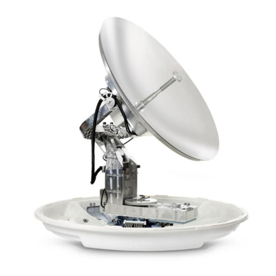
SAILOR 1000 XTR Ka 4.5W and 9W RF Pack
Brief Summary:
Field replacement document for replacing the Power Detector Housing.
Spare part:
S-67-175992 SAILOR XTR Ka 4.5W RF Pack
S-67-175993 SAILOR XTR Ka 9.0W RF Pack
Location of the part:
Following legal entities are trading as / doing business as Cobham SATCOM
Thrane & Thrane A/S, Kgs. Lyngby, Denmark
Sea Tel Inc., Concord USA
Field replacement procedure
Cobham SATCOM
Global Technical Service dept.
Date: November 2021
Document Number:
97-178838-A
www.cobham.com/satcom
Advertisement
Table of Contents

Related Manuals for COBHAM SAILOR 1000 XTR Ka 4.5W


Summary of Contents for COBHAM SAILOR 1000 XTR Ka 4.5W
- Page 1 S-67-175992 SAILOR XTR Ka 4.5W RF Pack S-67-175993 SAILOR XTR Ka 9.0W RF Pack Location of the part: Following legal entities are trading as / doing business as Cobham SATCOM Thrane & Thrane A/S, Kgs. Lyngby, Denmark Sea Tel Inc., Concord USA www.cobham.com/satcom...
- Page 2 Replacing the part: 1. Open the service hatch, loosen the 8 screws. Do not use a power tool! Access the pedestal through the hatch. Power off the ADU (at the ADU power on/off switch at the antenna control module). Remove the feed horn with a suitably sized wrench.
- Page 3 7. Disconnect the X-pol cable. 8. Remove the cable tie. 9. Remove the co-pol cable from the RF pack. 10. Take off the RF Package by turning it anti- clockwise and lift it off. 11. Leave the 4 loosely mounted screws at the back of the antenna dish.
- Page 4 14. Attach the co-pol cable to the new RF pack. 15. Add the cable tie. 16. Connect the X-pol cable. Tighten to 1 Nm. 17. Connect the TX coax cable connector. Connect the cable from the RF pack to the plug marked BUC M&C (a).
- Page 5 21. Switch on the antenna at the ADU power on/off switch at the antenna control module and check that the antenna goes through the POST (antenna can move freely). Close the hatch. Apply copper grease to thread of the 8 screws. Grease type: Rocol 250, Nulon 90, or Abcon 790.
Need help?
Do you have a question about the SAILOR 1000 XTR Ka 4.5W and is the answer not in the manual?
Questions and answers
Replacing Sailor 1000 XTR Ka 9w cross level meter
To replace a COBHAM SAILOR 1000 XTR Ka 4.5W with a SAILOR 1000 XTR Ka 9W system, use the SAILOR XTR 600 GX-R2 9W Transceiver Kit (part number 407522D-00540). This kit upgrades the 4.5W transceiver to 9W and includes the 9W GX-R2 transceiver and an alignment tool. The modem and feed horn are not included and must be reused or sourced separately.
This answer is automatically generated