Advertisement
Quick Links
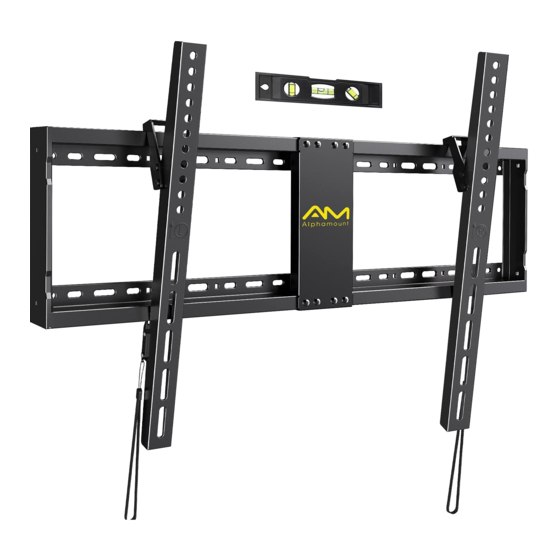
Large Tilting TV Wall Mount
Instruction Manual
V2.0
Model: APXTK2
Thank you for choosing this Alphamount product! At Alphamount we
strive to provide you with the best quality products and services in the
industry. Should you have any issues, please don't hesitate to contact at
support@alphamount.com (US/CA)
Advertisement

Related Manuals for Alphamount APXTK2


Summary of Contents for Alphamount APXTK2
- Page 1 Instruction Manual V2.0 Model: APXTK2 Thank you for choosing this Alphamount product! At Alphamount we strive to provide you with the best quality products and services in the industry. Should you have any issues, please don't hesitate to contact at...
-
Page 2: Weight Restrictions
Please carefully read all instructions before attempting installation. If you do not understand the instructions or have any concerns or questions, please contact our customer service at support@alphamount.com. CAUTION: Avoid potential personal injuries and property damage! • Do not use this product for any purpose that is not explicitly specified in this manual. -
Page 3: Supplied Parts And Hardware
Before starting assembly, verify all parts are included and undamaged. Do not use damaged or defective parts. lf you require replacement parts, please contact our customer service at support@alphamount.com. • Please note: Not all hardware included in this package will be used. - Page 4 Note: The bolts are shown in accordance with the actual size M6x15mm M6x35mm Bolt Bolt M8x15mm M8x35mm M8x50mm Bolt Bolt Bolt Supplied Parts and Hardware for Step 2 and 3 Wall Plate Connection Plate Level Note: The lag screw is shown in accordance with the actual size Lag Screw ST8x65 mm M8 Washer...
- Page 5 Please Note: When using the spacers it is important to note that they can be used in multi-layers (meaning stacked). If you have any difficulty understanding how to install the TV bolts or spacers, please contact customer service at support@alphamount.com. CAUTION: Ensure the TV brackets [03 and 04] are EQUALLY CENTERED on your TV and securely fastened in place.
- Page 6 Option B (For Round Back TV) B/D/E J/K/L Alternate Spacer Setups Option C (For TV with A “Bump”) Spacers may be necessary for 2 holes ONLY. B/D/E F/D2/E2/E3 (If needed) J/K/L B2/B3/B4 Alternate Spacer Setups (If needed) Option D For cable interference or inset holes, use spacers [J], [K] and [L] to create extra space between the TV and TV brackets J/K/L B/D/E...
- Page 7 Step 2 Assemble the Wall Plate(Optional) DO NOT overtighten. Tighten only until snug. Option A: 16 in. (406mm) stud spacing VESA Pattern of TV: 8x4 in.-16x16 in. (200x100-400x400mm) Option B: 16-24 in. (406mm-610mm) stud spacing or VESA Pattern of TV: 8x4 in.-32x16 in.(200x100-800x400mm) Loosen Loosen...
- Page 8 Step 3 Attach Wall Plate to Wall For wood stud installation, follow STEP 3A For concrete installation, follow STEP 3B Step 3A Wood Stud Option WARNING: Avoid potential personal injury or property damage! DO NOT over-tighten the lag screws [F]. Tighten the lag screws [F] only until the washers [G] are pulled firmly against the wall plate [01].
- Page 9 3A-3 Drill 4 pilot holes using a 7/32 in. (5.5mm) diameter drill bit. Make sure the depth is not less than 2 9/16 in. (65mm) 2 9/16 in. (65mm) 7/32 in. (ø5.5mm) 3A-4 Install the wall plate [01] using lag screws [F] and washers [G].
- Page 10 3B-1 3B-2 Position the wall plate at your Drill 4 pilot holes using a 3/8 in. desired height, level the wall plate (10mm) diameter drill bit. Make sure and mark the pilot hole locations. the depth is not less than 2 3/4 in. (70mm).
- Page 11 Step 4 Adjust Tilt Angles of TV Note: Do not over-tighten or over-loosen the bolts [S] 5/16in. (8mm) Wrench (Not Included) Tighten Loosen Note: The tilt angles of the hooks on the TV brackets must be the same Slightly loosen the 2 preassembled tilt tension bolts [S] on both brackets. Adjust the hooks of the brackets to the desired angle, then tighten tilt tension bolts with a wrench (not included) and a screwdriver (not included) to fix the tilting angle of the TV.
- Page 12 Locking Locking P r e s s P r e s s While pulling and hold both ropes [R] , press the bottom of the TV into the wall plate [01] until the latches lock into the wall plate, then release the ropes.
Need help?
Do you have a question about the APXTK2 and is the answer not in the manual?
Questions and answers