
Related Manuals for Lütze LION-DI16-DO8-S-LV


Summary of Contents for Lütze LION-DI16-DO8-S-LV
- Page 1 Operating Instructions LION SIL2 I/O Modules LION-DI16-DO8-S-LV LION-DI16-DO8-HV Version 00 01/24/2017...
- Page 2 Lütze Transportation GmbH Bruckwiesenstraße 17-19 D-71384 Weinstadt Tel.: +49 (0) 7151 6053-545 Fax: +49 (0) 7151 6053-6545 Sales.Transportation@luetze.de www.luetze-transportation.de...
-
Page 3: Table Of Contents
▪ LION I/O Modules Content Content Instruction Content..................6 General Information..................7 Symbol Description ......................... 7 2.1.1 Safety Messages........................7 2.1.2 Handling Notes........................7 2.1.3 Special Notes .......................... 7 Copyright..........................7 Disclaim of Liability........................8 Standards..........................8 Labeling........................... 8 2.5.1 QR Code –... - Page 4 ▪ LION I/O Modules Content Demounting........................... 29 Grounding the Modules......................30 Wiring the Modules ....................... 31 Terminal coding........................32 6.7.1 Locking the Push-In Terminals....................32 6.7.2 Releasing the Push-In Terminals ..................32 EMC Shield Clip Set......................33 6.8.1 Measurements ........................33 6.8.2 Mounting ..........................
- Page 5 ▪ LION I/O Modules Content 11.3 Extending the LION System....................62 Final Shutdown and Disposal..............63 Appendix...................... 64 13.1 Accessories........................... 64 13.2 Revision of the Document ..................... 64...
-
Page 6: Instruction Content
▪ LION I/O Modules Instruction Content Instruction Content This manual is part of the LION I/O Modules. It contains important information about the handling and safety. ▪ To avoid hazardous situations, read the manual before installing the product and using it.This applies to every person who is getting in touch with the product. -
Page 7: General Information
▪ LION I/O Modules General Information General Information Symbol Description 2.1.1 Safety Messages The manual contains several safety messages. Each safety message contains a defined signal word and a color. The color and the word are referring to an alert level. -
Page 8: Disclaim Of Liability
▪ LION I/O Modules General Information Disclaim of Liability The manual was written under consideration of the applied standards, regulations and the current state of technology. The content is verified of accuracy. Discrepancies are not excluded. For those discrepancies we disclaim liability. Applicable changes and additional information will be in the next version of the manual. -
Page 9: Qr Code - Product Information
▪ LION I/O Modules General Information Mind the adhesive labels. ▪ Keep them readable. ▪ In case of a malfunction the part number and the serial number might be needed. www.luetze.com 803101.01 Rev. A D-71384 Weinstadt LION-DI16-24V-36V-LUE 16DI DC 24 V-36V Date: 31.12.12 1.00 LSGP... -
Page 10: Safety
▪ LION I/O Modules Safety Safety Related Documents The modules are always operated with other LION modules. Risk of injury and property damages caused by non observance of the related documents. ▪ The manual of the components is insufficient if operating in a system with other modules. -
Page 11: Operating Employees
▪ LION I/O Modules Safety Operating Employees Risk of injury by deploying insufficient qualified operating employees. Inappropriate appoint of not qualified or insufficient personnel can cause property damages and personal injuries. ▪ Tasks which apply special procedures should be done by trained and qualified employees or experts, especially electricians. -
Page 12: Reconstruction And Modifications Of The Product
▪ LION I/O Modules Safety ▪ Switch off the voltage before working with or on the module and work according the ESD guidelines. ▪ Electronic components should not be contact electronic insulated material like plastic foil, plastic parts, insulated table pads or clothing. ▪... -
Page 13: System Planning
▪ LION I/O Modules System Planning System Planning Danger of life, serious injuries and property damages if planning a system with an incorrect system architecture. ▪ Check the technical data of each module. ▪ Read the operating instruction, especially the system and product description. -
Page 14: System Approvals
▪ LION I/O Modules System Planning System Approvals The system is certified. The system integrator or vehicle manufacturer can use LION-005 the certificate for vehicle registration. relevant The Approval is only valid for the whole LION SIL2 system. LION-006 ▪ The single infrastructure modules do not have an approval. -
Page 15: Power Supplies
▪ LION I/O Modules System Planning ▪ Safe receiving, processing and puting out the received process information via fieldbus in an environment up to SIL2. 4.3.3 Power Supplies ▪ Safe voltage supplying of the internal system regarding the specified thresholds for the upper voltage limit of the modules on the local bus in an environment up to SIL2. -
Page 16: System Overview
▪ LION I/O Modules System Planning System Overview LION (Lütze Input Output Network) is a decentral safety input and output system for railway vehicles. Fig.4: Overview – Bus coupler with connected I/O Modules The LION product line contains modular components and modules for capturing and releasing digital and analog signals. -
Page 17: Bus Coupler - Sil2
▪ LION I/O Modules System Planning 4.4.1 Bus Coupler – SIL2 Fig.5: Bus coupler The SIL2 bus coupler can be a gateway to a superior network, like the vehicle control, or it can be connected via fieldbus to a PLC. The bus coupler uses a safe fieldbus protocol. -
Page 18: Digital Output Modules - Sil0
▪ LION I/O Modules System Planning 4.4.3 Digital Output Modules – SIL0 Fig.7: Digital Output Modules The modules release digital information on the galvanic insulated output ranges via L-Bus . The outputs can have relays or semiconductors for a defined nominal voltage. -
Page 19: Analog Input Modules - Sil0
▪ LION I/O Modules System Planning 4.4.4 Analog Input Modules – SIL0 Fig.8: Analog Input Modules The modules capture analog input signals in the definied voltage range via galvanic insulated input ranges. The information are transmitted via L-Bus² to the SIL2 bus coupler. -
Page 20: Analog Output Modules - Sil0
▪ LION I/O Modules System Planning 4.4.5 Analog Output Modules – SIL0 Fig.9: Analog Output Modules The modules release analog information on the galvanic insulated output ranges via L-Bus². The outputs can base on relays or semiconductors for a defined nominal voltage. -
Page 21: Digital Input/Output Modules - Sil2
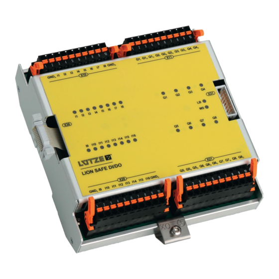
▪ LION I/O Modules System Planning 4.4.6 Digital Input/Output Modules – SIL2 LION SAFE DI/DO I11 I12 I13 I14 I15 I16 GND Fig. 10: SIL2 Digital Input and Output Modu- The modules capture digital input signals in the defined voltage range via galvanic insulated input ranges. - Page 22 ▪ LION I/O Modules System Planning line, an additional SIL2 bus coupler is not mandatory. If using a SIL0 line coupler, also a SIL2 power supply must be used. Every new line starts with a SIL2 power supply, followed by the SIL0 line coupler. The SIL0 line coupler is transparent for the system and the transmission protocol.
-
Page 23: System Architecture
▪ LION I/O Modules System Planning System Architecture Different system architectures can be realized with the LION product family. Following points are important to realize a system: ▪ The SIL2 bus coupler is the master of the LION system, the SIL0 I/O modules are slaves. -
Page 24: Maximum System
▪ LION I/O Modules System Planning 4.5.2 Maximum System The maximum system contains: ▪ three lines and two line changes ▪ one SIL2 bus coupler ▪ 32 SIL0/SIL2 I/O modules and ▪ a SIL2 power supply at the beginning of every line. With the help of an additional SIL2 power supply, SIL0/SIL2 I/O modules can be attached galvanic insulated. -
Page 25: Line Change
▪ LION I/O Modules System Planning 4.5.4 Line Change The LION system can be subdivided in three galvanic insulated sections (lines). For the galvanic insulation, a SIL0 line coupler must be installed at the end of the line and at the beginning of the following line. The SIL0 line couplers are transparent and not visible as a SIL2 bus subscriber. -
Page 26: Transport And Storing
▪ LION I/O Modules Transport and Storing Transport and Storing ▪ Product damages caused by humidity. Store the products in a dry environment between -40° and 85°C. ▪ Product damages caused by non safely packed products. Wrap the products safely for transporting to absorbe possible crushes. ▪... -
Page 27: Installation
▪ LION I/O Modules Installation Installation Risk of injury by electric shock. People can be injured by electric shocks and the product can be damaged. ▪ Deenergize the system before mounting. The modules have to be handled by electrically qualified persons. Mounting Options The Modules can be mounted on DIN rail TS35. -
Page 28: Din Rail Mounting
▪ LION I/O Modules Installation ▪ 5 mm ▪ Bottom Without PE extension: 5 mm With PE extension: 20 mm ▪ Side 0 mm Fig. 21: Mounting Distances DIN Rail Mounting ▪ The modules resist up to 100 times of mounting and demounting. ▪... -
Page 29: Demounting
▪ LION I/O Modules Installation Demounting Each module can be demounted seperately. 1. Release the wired terminals of the modules. 2. Push up the module. 3. Pull the module from the DIN rail. 4. Push down the module and take the module off the rail. -
Page 30: Grounding The Modules
▪ LION I/O Modules Installation Grounding the Modules Electric shocks and injuries because of wrong grounding. ▪ Do not ground the modules via top hat rail. ▪ Always ground the modules via the PE connection. ▪ It is also mandatory to ground the DIN rail for EMC reasons. ▪... -
Page 31: Wiring The Modules
▪ LION I/O Modules Installation Wiring the Modules All modules have terminals with Push-In technology. The terminals are printed with white pin numbers, starting with 1. Via terminals, the sensors and actuators of the modules will be connected. It is possible to connect the modules with pre-assembled cables. -
Page 32: Terminal Coding
▪ LION I/O Modules Installation Terminal coding It is possible to code the Push-In terminals with coding pins, which are in the scope of delivery. The coding prevents polarity reversal. 1. Push in the coding pin for the termi- nal. 2. -
Page 33: Emc Shield Clip Set
▪ LION I/O Modules Installation EMC Shield Clip Set To ensure EMC performance, according to the EN 50155, it is mandatory to install a shield clip set on the analog modules. The EMC shield clip set (Part-No. 800204) is not in the scope of delivery. 6.8.1 Measurements Fig. -
Page 34: Wiring
▪ LION I/O Modules Installation 6.8.3 Wiring 1. Connect the modules with the sing- le conductors of the cable. 2. Remove the jacket of the cable, where the shield clip will be, until the cable shield can be seen. 3. Fix the cable with the shield clip, the cable shield must have contact to the shield clip. -
Page 35: Disconnecting The Modules
▪ LION I/O Modules Installation 1. Plug in the L-Bus connector and push it down. 2. Push down the sides of the plug until a click can be heard. Fig. 32: L-Bus – Module Connection 6.10 Disconnecting the Modules 1. Push the sides of the connector. 2. -
Page 36: System Termination
▪ LION I/O Modules Installation 6.11 System Termination 6.11.1 Bus Termination Connector The termination connector (Part-No. 800201) is not in the scope of delivery. It has to be purchased additionally. Fig. 34: LION System – Termination On the last module of the L-Bus², a bus termination connector must be installed. The terminator is responsible for: ▪... -
Page 37: Product Description
▪ LION I/O Modules Product Description Product Description The LION SIL2 I/O modules are specially designed for the use in a LION application. The modules read and transmit diagnostic and process data like error or channel/port status. The modules can be connected to a bus coupler or a PLC, where the data will be processed. -
Page 38: Product Overview
▪ LION I/O Modules Product Description ▪ Varistor/Suppressor diode – protection against overvoltage (surge), inductive cut-off voltage ▪ Switching mechanism for short circuits/overload and overtemperature Product Overview LION SAFE DI/DO I11 I12 I13 I14 I15 I16 GND Abb. 36: Module Overview X30: L-Bus interface, incoming bus, female connector IDE, 14-pin X10: Push-In terminal for input signals... -
Page 39: Interfaces - Pin Assignment
▪ LION I/O Modules Product Description Environmental Condition Operating Temperature -40°C…+70° (+85°C 10 min) Storing Temperature -40°C…+85° Protection Class IP20 Bus interface Bus system L-Bus Module type Slave I/O module Transmission medium Flat conductor, 14-pin L-Bus Interfaces – Pin Assignment Digital Inputs –... - Page 40 ▪ LION I/O Modules Product Description Digital Inputs – X20 I11 I12 I13 I14 I15 I16 GND Signal Operation GND (Potentialgroup C) Input 9 (Potential C) Input 10 (Potential C) Input 11 (Potential C) Input 12 (Potential C) Input 13 (Potential D) Input 14 (Potential D) Input 15 (Potential D) Input 16 (Potential D)
-
Page 41: Led Status
▪ LION I/O Modules Product Description LED Status When powering the SIL2 I/O modules, a selftest will be started. All LEDs of the module will turn on for 500 ms. Every SIL2 IO module has an L-Bus² status LED (LB) and a module status LED (MS). -
Page 42: Module Status
▪ LION I/O Modules Product Description Abb. 39: LED – Digital Outputs Color Status Description Q1 – Q8 yellow Output switched off Output switched on/operating flashing fast Error at the output (2 x 5 Hz + break) Module Status During the start and shut down of the system, all outputs are in the safe mode. LION-054 relevant All input signals are “invalid“, which refers to the safe mode. -
Page 43: Fail Safe
▪ LION I/O Modules Product Description Master transfers a message to all slaves modules to change into run mode. The L-Bus runs without errors. Cyclic communication with the process data. No time exceed. error Occurirng of a minor error (e.g. local I/O peripherie is disturbed), the module changes into the limited run mode. -
Page 44: Limited Run
▪ LION I/O Modules Product Description 7.6.2 Limited Run Criteria Reaction Clearly localizable error function e.g. of The malfunctioned channel will be LION-069 an I/O channel. transfered in the safe mode. relevant... -
Page 45: Safe Data Communication
▪ LION I/O Modules Safe Data Communication Safe Data Communication The safe data communication of the SIL2 IO modules is only possible with a SIL2 LION-011 bus coupler and a connected SIL2 PLC. For the data communication, a safe protocol is needed to reach the SIL2 level. relevant The outputs do only reach SIL2 if the connected actuator has an plus/minus switching architecture. - Page 46 ▪ LION I/O Modules Safe Data Communication The safe and transformed data will be sent via safe SDTv2 protocol on the MVB to the PLC.
-
Page 47: Outputs
▪ LION I/O Modules Safe Data Communication Outputs The SIL2 I/O module switches the outputs, captures the diagnosis information and tests/checks the outputs. The data will be transferred via safe protocol from the SIL2 bus coupler to the PLC. The PLC evaluates the data and carries out a safe orientated error reaction if necessary. -
Page 48: Digital Inputs
▪ LION I/O Modules Digital Inputs Digital Inputs The inputs capture sensor signals in the voltage range of DC 24 V…36 V (Part- No. 803501) and DC 72 V…110 V (Part-No. 803502). Error Detection For the error detection there are two diagnosis functions implemented: LION-038 Testpulse To recognize “Stuck at high“... -
Page 49: Sil1
▪ LION I/O Modules Digital Inputs ▪ Not only the architecture is relevant of reaching a SIL level, also the THR value. Read the LION System Description for more information. ▪ The SIL2 level can also be reached with a one channel architecture if the THR of the whole system is sufficient. -
Page 50: Sil2
▪ LION I/O Modules Digital Inputs 9.2.2 SIL2 Two Channel Architecture – With a Contact based Sensor and valent LION-059 Contacts relevant MVB / TRDP MVB / TRDP with SDT with SDT CH1 CH2 Sensor Signal Sensor Signal Two Channel Architecture – With Contact based Sensor and antivalent Contacts MVB / TRDP MVB / TRDP... -
Page 51: Process Data Image
▪ LION I/O Modules Digital Inputs Process Data Image 9.3.1 Input Data Input Data Process data, per channel Signal level [1 Bit per channel] Diagnosis data, per channel Error, Test pulse evaluation [1 Bit per channel] Process Data per Channel These process data are signalising the safe status, which is 0 –... - Page 52 ▪ LION I/O Modules Digital Inputs ERROR 2 0 or 1 (Potential A) ERROR 3 0 or 1 (Potential A) ERROR 4 0 or 1 (Potential A) ERROR 5 0 or 1 (Potential B) ERROR 6 0 or 1 (Potential B) ERROR 7 0 or 1 (Potential B) ERROR 8...
-
Page 53: Digital Outputs
▪ LION I/O Modules Digital Outputs Digital Outputs The outputs are potential free semiconductor switches for the nominal voltage range of DC 24 V…110 V. 10.1 Error Detection Following status can be diagnosis by the outputs: LION-040 ▪ Switching status of the transistor relevant The voltage difference on fthe switching transistor is measured. -
Page 54: Safety Integrity
▪ LION I/O Modules Digital Outputs 10.2 Safety Integrity The SIL1 level can be reached ▪ if the output is recognized as a one channel switching output ▪ as a high side switch (switches loads against mass) and ▪ if a single switching output is realized in the redundant operation, but the THR values must admit it. -
Page 55: Sil1
▪ LION I/O Modules Digital Outputs 10.2.1 SIL1 Single Switching Output LION-060 relevant MVB / TRDP MVB / TRDP with SDT with SDT Actuator Double switching parallel for redundant operation Single Switching Output LION-061 relevant MVB / TRDP MVB / TRDP with SDT with SDT Actuator... -
Page 56: Sil2
▪ LION I/O Modules Digital Outputs 10.2.2 SIL2 Double plus/minus switching LION-062 relevant MVB / TRDP MVB / TRDP with SDT with SDT Act. 10.3 Process Data Image 10.3.1 Input Data Input Data Diagnosis data, per channel Switching status of outputs [1 Bit per channel] Switching status of output transistors [1 Bit per channel]... - Page 57 ▪ LION I/O Modules Digital Outputs Diagnosis Data, per Channel Switching Status Outputs Channel Status Binary Value Output off Output on Data structure Channel Content 0 or 1 0 or 1 0 or 1 0 or 1 0 or 1 0 or 1 0 or 1 0 or 1...
- Page 58 ▪ LION I/O Modules Digital Outputs Data Structure Channel Content 0 or 1 0 or 1 0 or 1 0 or 1 0 or 1 0 or 1 0 or 1 0 or 1 Error Signalisation – Test Pulse Evaluation Channel Status Binary Value No error...
-
Page 59: Configuration Data - Filter Constant
▪ LION I/O Modules Digital Outputs 0 or 1 (configuration data) – – – – – – 10.3.2 Configuration Data – Filter Constant The filter constant defines the time lag of the data capture of input signals. For setting the time lag, one bit per byte has to be set to 1, all other bits in the byte must be 0. -
Page 60: Output Data
▪ LION I/O Modules Digital Outputs 10.3.3 Output Data Output Data Process data, per channel Target status of outputs [1 Bit per channel] Processdata, per Channel Target Status Outputs Channel Status Binary Value Output off Output on Data structure Channel Content 0 or 1 0 or 1... -
Page 61: Maintenance And Service
▪ LION I/O Modules Maintenance and Service Maintenance and Service The system and the single modules do not require a preventive maintenance. If you have any further questions regarding the product or our repairing service, please contact us: Lütze Transportation GmbH Bruckwiesenstraße17-19 71384 Weinstadt Tel.: +49 (0) 7151 6053-545... -
Page 62: Extending The Lion System
▪ LION I/O Modules Maintenance and Service 11.3 Extending the LION System Risk of injury by deploying insufficient qualified operating employees. Inappropriate appoint of not qualified or insufficient personnel can cause property damages and personal injuries. ▪ The extending of the LION system applies special procedures and must be done by trained and qualified employees or experts, especially electricians. -
Page 63: Final Shutdown And Disposal
▪ LION I/O Modules Final Shutdown and Disposal Final Shutdown and Disposal Mind the valid environmental standard of your country for the final shutdown and disposal. For the final shutdown, the device has to be disassembled. Electric parts must be disposed after the national electronic scrap regulation. -
Page 64: Appendix
▪ LION I/O Modules Appendix Appendix 13.1 Accessories Description Type Part-No. L-Bus Termination Connector LION-LB-TERM-CON 800201 L-Bus Dummy Connector LION-LB-DUM-CON 800202 L-Bus 1:1 Connecting Cable LION-LB-1:1-CON 800203 EMC Shield Clip Set LION-SHIELD-CLIP-SET 800204 Connection cable for Line LION-LC-CABLE-10M 800205 Coupler (LC) Length = 10 m Connection cable for LION-LC-CABLE-5M 800206...
Need help?
Do you have a question about the LION-DI16-DO8-S-LV and is the answer not in the manual?
Questions and answers