
Related Manuals for Lütze LION-BC-ETH-LUE


Summary of Contents for Lütze LION-BC-ETH-LUE
- Page 1 Operating Instructions LION Bus Coupler Ethernet (SIL0) LION-BC-ETH-LUE 803012 Version 01 03/19/2019...
- Page 2 Lütze Transportation GmbH Bruckwiesenstraße 17-19 D-71384 Weinstadt Tel.: +49 (0) 7151 6053-545 Fax: +49 (0) 7151 6053-6454 Sales.Transportation@luetze.de www.luetze-transportation.de...
-
Page 3: Table Of Contents
▪ LION Bus Coupler Content Content Instruction Content................... 6 General Information..................7 Symbol Description........................7 Copyright ............................. 7 Disclaim of Liability ........................8 Standards ..........................8 Labeling ............................9 Safety ....................... 10 Related Documents ........................10 Intended Use ..........................11 Recepients.......................... - Page 4 ▪ LION Bus Coupler Content 10.1 - not applicable - ........................59 10.2 LION Webserver ........................59 10.3 System Test..........................62 Operation......................63 11.1 Webserver Monitoring........................ 63 Error Handling....................70 12.1 Error Codes ..........................71 Maintenance and Service................72 13.1 Module Exchange ........................72 13.2 Proof Test Interval ........................
-
Page 5: Instruction Content
Instruction Content Instruction Content This manual is part of the LION Bus Coupler Ethernet (SIL0) (Part-No. 803012, Type LION-BC-ETH-LUE). It contains important information about the handling and safety. ▪ To avoid hazardous situations, read the manual before installing the product and using it.This applies to every person who is getting in touch with the... -
Page 6: General Information
▪ LION Bus Coupler General Information General Information Symbol Description 2.1.1 Safety Messages The manual contains safety information, which is characterized by a signal word in combination with a certain colour to indicate the warning level. The information highlights possible dangers and gives instructions on how to avoid them. Indicates a dangerous situation which leads to death or serious injuries if not observed. -
Page 7: Disclaim Of Liability
▪ LION Bus Coupler General Information Disclaim of Liability The manual was written under consideration of the applied standards, regulations and the current state of technology. The content is verified of accuracy. Discrepancies are not excluded. For those discrepancies we disclaim liability. Applicable changes and additional information will be in the next version of the manual. -
Page 8: Labeling
▪ LION Bus Coupler General Information Labeling Mind the adhesive labels. ▪ Keep them readable. ▪ In case of a malfunction the part number and the serial number might be needed. www.luetze.com 803101.01 Rev. A D-71384 Weinstadt LION-DI16-24V-36V-LUE 16DI DC 24 V-36V Date: 31.12.12 1.00 LSGP... -
Page 9: Safety
▪ LION Bus Coupler Safety Safety Related Documents The LION Bus Coupler is always operated together with I/O modules and infrastructure components. It is essential to have read and understood the relevant documents. Risk of injury and property damages caused by non observance of the related documents. -
Page 10: Intended Use
▪ LION Bus Coupler Safety 3.1.4 Data sheet of the LION Bus coupler Ethernet The data sheet contains the current technical data. Technical data are subject to change without notice. Be sure to use the latest data. >This link opens the product data as well as the data sheet on the LÜTZE Transportation website. -
Page 11: Responsibility Of The Operator
▪ LION Bus Coupler Safety Responsibility of the Operator The operator is obligate by the law of occupational safety, if the product is used in a commercial field. ▪ The operator is responsible to train the employees and to inform himself about the industrial safety regulation. -
Page 12: Special Safety Messages
▪ LION Bus Coupler Safety Special Safety Messages Electric shocks and product damages caused by wrong voltage application. ▪ Use the nominal operating voltage (see technical data). ▪ The lower and upper thresholds are given in the technical data. Product damages caused by compensating current. ▪... -
Page 13: System Planning
▪ LION Bus Coupler System Planning System Planning Danger of life, serious injuries and property damages if planning a system with an incorrect system architecture. ▪ Check the technical data of each module. ▪ Read the operating instruction, especially the system and product description. -
Page 14: Lion System - Overview
▪ LION Bus Coupler System Planning LION System - Overview Fig. 3: LION System overview (SIL0/SIL2) Using the SIL0 bus coupler only SIL0 can be reached. -
Page 15: Safety Target
▪ LION Bus Coupler System Planning Safety Target Using the SIL0 bus coupler only SIL0 can be reached. 4.3.1 Bus Coupler ▪ Transmitting of process information from the PLC to the connected I/O modules on the local system bus and vice versa in an environment up to SIL0. 4.3.2 I/O Modules ▪... - Page 16 ▪ LION Bus Coupler System Planning 4.4.1 Bus Coupler Ethernet TRDP (SIL0) LNK1 LNK2 LION BC ETH ACT1 ACT2 LNK1 LNK2 LION BC ETH ACT1 ACT2 Fig.5: Bus coupler The Bus Coupler Ethernet (SIL0) can be a gateway to a superior network, like the vehicle control, or it can be connected via fieldbus to a PLC.
- Page 17 ▪ LION Bus Coupler System Planning 4.4.3 Digital Output Modules (SIL0) Fig.7: Digital Output Modules The modules release digital information on the galvanic insulated output ranges via L-Bus . The outputs can have relays or semiconductors for a defined nominal voltage.
- Page 18 ▪ LION Bus Coupler System Planning 4.4.4 Analog Input Modules (SIL0) Fig.8: Analog Input Modules The modules capture analog input signals in the definied voltage range via galvanic insulated input ranges. The information are transmitted via L-Bus² to the bus coupler. Product Description Type...
- Page 19 ▪ LION Bus Coupler System Planning 4.4.5 Analog Output Modules (SIL0) Fig.9: Analog Output Modules The modules release analog information on the galvanic insulated output ranges via L-Bus². The outputs can base on relays or semiconductors for a defined nominal voltage. Product Description Type...
- Page 20 ▪ LION Bus Coupler System Planning 4.4.6 Digital Input/Output Modules (SIL2) LION SAFE DI/DO I11 I12 I13 I14 I15 I16 GND Fig. 10: SIL2 Digital Input and Output Module The modules capture digital input signals in the defined voltage range via galvanic insulated input ranges.
- Page 21 ▪ LION Bus Coupler System Planning 4.4.7 Infrastructure Modules (SIL0/SIL2) Fig.11: Power Supplies & Line Coupler For the infrastructure, two power supplies (SIL0), two power supplies (SIL2) and a line coupler (SIL0) are available. With the SIL0 line coupler, the bus can be interrupted and continued in the next line, an additional bus coupler is not mandatory.
- Page 22 ▪ LION Bus Coupler System Planning Power Supply For nominal supply values LION-PS-24V- 800113 36 W, for the battery supply from 110V-36W SIL0 DC 24 V to DC 110 V with galvanic insulation. The output rating is 36 W. Line Coupler, For spacial and galvanic LION-LC-M12 800102...
-
Page 23: System Architecture
▪ LION Bus Coupler System Planning System Architecture Different system architectures can be realized with the LION product family. Following points are important to realize a system: ▪ The SIL0/SIL2 bus coupler is the master of the LION system, the SIL0/SIL2 I/O modules are slaves. - Page 24 ▪ LION Bus Coupler System Planning 4.5.2 Maximum System The maximum system contains: ▪ three lines and two line changes ▪ one SIL0/SIL2 bus coupler ▪ 32 SIL0/SIL2 I/O modules and ▪ a SIL0/SIL2 power supply at the beginning of every line. With the help of an additional SIL0/SIL2 power supply, SIL0/SIL2 I/O modules can be attached galvanic insulated.
- Page 25 ▪ LION Bus Coupler System Planning 4.5.4 Line Change The LION system can be subdivided in three galvanic insulated sections (lines). For the galvanic insulation, a SIL0 line coupler must be installed at the end of the line and at the beginning of the following line. The SIL0 line couplers are transparent and not visible as a bus subscriber.
- Page 26 ▪ LION Bus Coupler System Planning 4.5.5 Energy Supply Range A SIL0/SIL2 power supply supplies all components that are on the right. The system can be subdivided in different sections. If the maximum energy requirement of the modules exceeds the nominal value of the power supply, the sections need to be supplied by an additional SIL0/SIL2 power supply.
-
Page 27: Transport And Storing
Store and transport electronic components only in ESD safe and conductive packaging. Scope of Delivery ▪ 1 × LION Bus Coupler Ethernet (SIL0) (Part-No. 803012, Type LION-BC-ETH-LUE) ▪ 1 × Instruction leaflet (Part-No. 919819.0000) ▪ 1 × L-Bus Termination Connector (Part-No. 800201) ▪... -
Page 28: Installation
▪ LION Bus Coupler Installation Installation Risk of injury by electric shock. People can be injured by electric shocks and the product can be damaged. ▪ Deenergize the system before mounting. The modules have to be handled by electrically qualified persons. LION System Description –... -
Page 29: Product Description
▪ LION Bus Coupler Product Description Product Description The LION Bus Coupler Ethernet (SIL0) is specially designed for the use in a LION application. The LION Bus Coupler Ethernet (SIL0) is the connection between the TRDP/Ethernet based TCN and the LION SIL0/SIL2 input and output modules. The LION Bus Coupler Ethernet (SIL0) is TRDP End Device on the fieldbus and L-Bus master. -
Page 30: Product Overview
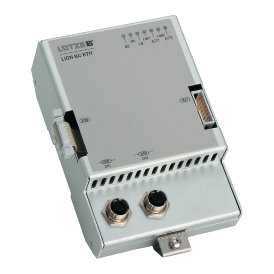
▪ LION Bus Coupler Product Description Product Overview LNK1 LNK2 LION BC ETH ACT1 ACT2 www.luetze.com 80XXXX Rev. A D-71384 Weinstadt Modulbeschreibung 1 Modulbeschreibung 2 MAC-ID Date: TT.MM.JJ X.YY ZZZZZ C/N: YNNNNN S/N: 0000000001 Fig. 17: Product Overview – Bus coupler Ethernet X50: Ethernet Interface 1 (CH1) X60: Ethernet Interface 2 (CH2) X30: L-Bus²... -
Page 31: Led Status
▪ LION Bus Coupler Product Description LED Status When powering the module, a selftest will be started. That means every LED besides the LNK and ACT LED will turn on for 500 ms. LNK1 LNK2 ACT1 ACT2 Fig. 18: Status LED 7.4.1 MS (Modul Status) LED Color... - Page 32 ▪ LION Bus Coupler Product Description LNK1 LNK2 ACT1 ACT2 Fig. 19: Status LED 7.4.4 Ethernet Interface 1 (LNK1), (ACT1) LED Color Status Description LNK1 green Ethernet CH1 connection green Ethernet CH1 no connection Color Status Description ACT1 yellow Ethernet CH1 data transfer ...
-
Page 33: Module Status
▪ LION Bus Coupler Product Description Module Status If an error occurs during the start up time in the configuration, the module will be in the limited run but it will still send valid process data to the connected modules. During the operation, the bus coupler can and will be in different operation modes: Modul Status Description... -
Page 34: Failsafe
▪ LION Bus Coupler Product Description 7.5.1 Limited Run Criteria and reaction for the limited run mode: Criteria Reaction One or more modules are missing. The master is only communicating with Type and position of the existing the correct available modules. The modules are correct. -
Page 35: Ethernet - Interface X50/X60 Trdp Fieldbus And Diagnosis
▪ LION Bus Coupler Product Description Ethernet – Interface X50/X60 TRDP Fieldbus and diagnosis M12 Connector, D-coded according to IEC 61076-2-101-A1, with shield connector pin. ▪ Compatible with the network standard Ethernet 802.3 100BASE-TX. ▪ Interface according to 100Base-TX, according IEEEE 802.3 Clause 25. ▪... -
Page 36: Supply Interface - X30 L-Bus2
▪ LION Bus Coupler Product Description 7.10 Supply Interface – X30 L-Bus The bus coupler is supplied by an external LION power supply via interface X30. 7.11 Signal and Supply Interface – X31 L-Bus The interface supplies the connected I/O modules and is responsible for the signal communication between bus coupler and I/O modules. -
Page 37: Function
▪ LION Bus Coupler Function Function Data Communication Fig. 20: Symbolic illustration In the system, the bus coupler communicates with the I/O modules via L-Bus Input and output data are transferred. The I/O modules get data from connected sensores or transmit data to connected actuators, depending on the module type. 8.1.0.1 Process Data The data, that is transferred, consists of process and status information, depen-... - Page 38 ▪ LION Bus Coupler Function 8.1.1.1 Message Data Beneath TRDP process data the bus coupler is capable to transmit non cyclic data via TRDP message data. This data has to be mapped on the bus coupler's Telegrams .The mapping is done in the LION Framework. 8.1.1.2 Listener The bus coupler adds listeners for each configured messagedata telegram to...
- Page 39 ▪ LION Bus Coupler Function 8.1.4 Diagnostic Telegram To be able to diagnose the LION station during operation a diagnostic telegram has to be configured (set in the configuration file). The diagnostic telegram can be configured as process data publisher or UDP message data listener.
-
Page 40: General Monitoring
▪ LION Bus Coupler Function 8.1.4.1 Slot Status The slot status of the I/O modules contains the validity and the availability of the process and diagnosis values. If following error occures, the slot status is set: ▪ I/O module is missing ▪... -
Page 41: Configuration
▪ LION Bus Coupler Configuration Configuration The project planner is responsible for the configuration. Especially for the correct mapping of the process and diagnosis data between bus coupler and I/O modules. The bus coupler communicates with the I/O modules via L-Bus with a safe protocol. -
Page 42: Lion Framework
▪ LION Bus Coupler Configuration LION Framework The LION Framework is a tool for generating bus coupler configuration files and for configuring a LION system. The LION Framework is necessary to generate the TDB file (configuration), it is not possible to configure the bus coupler in another way. 9.3.1 Download and Installation The TRDP buscoupler requires the LION configuration Framework... - Page 43 ▪ LION Bus Coupler Configuration 9.3.2 Generating a Configuration file – IODB and TDB Before starting the TRDP configuration, an IODB must be generated. The IODB shows the set up of the LION System. 1. Create a new IODB. 2. Choose the modules from the toolbox which you installed in your system.
- Page 44 ▪ LION Bus Coupler Configuration 5. To add a module to the end just drag and drop it on the right side of the last module. A red line gets displayed where the module will be placed. 6. To add a module between two existing modules just drag and drop it between the these modules.
- Page 45 ▪ LION Bus Coupler Configuration 7. To delete a module just drag and drop it to the bin symbol with the exclamation mark. It is also possible to mark the module by left clicking it and delete it by pressing delete. 8.
- Page 46 ▪ LION Bus Coupler Configuration 11.Import the created IODB. If all steps are done, different sink and source telegrams can be created and the mapping of the I/O data to the telegrams can be done. The LION Framework stores all information about the TRDP configuration as XML file compliant to the definition in the IEC 61375-2-3 with some modification to store additional information about the LION I/O system.
- Page 47 ▪ LION Bus Coupler Configuration 9.3.3 General Information Administrative Data Version Version of the TRDP file/configuration Date Modification date Description User description for the configuration, only used in LION Framework for documentation. Version Version of the TDB file/configuration TRDP-Slave Data Host-Name Optional host name for DNS/DNR Type...
- Page 48 ▪ LION Bus Coupler Configuration 9.3.4 DataSets DataSets describe the structure of the data sent in TRDP telegrams. Before creating a Telegram the data structure has to be described in a dataset. Please mind that changes in the data structure of allready mapped telegrams can lead to loss of the mapping information.
- Page 49 ▪ LION Bus Coupler Configuration Add Elements to Datasets Elements need to be added to datasets to transfer data. A dataset can be used to store elements or as a Diagnostic Dataset. Diagnostic Data Set: Use as diagnostic Click to add diagnostic data to the DataSet. Afterwards the DataSet structure of the diagnostic dataset is loaded.
- Page 50 ▪ LION Bus Coupler Configuration Com Parameters In TRDP it is possible to add com parameter settings to change the behaviour of the network transmitting this data. This is done by creating Com Parameter entries and reference them in telegrams by ID. To add a new Com Parameterset select "Com-Parameter"...
- Page 51 ▪ LION Bus Coupler Configuration MD_Com-Parameter: Confirm-Timeout Default comfirm timeout time [us] (see IEC 61375-2-3 for details) Reply-Timeout Default reply timeout [us] (see IEC 61375-2-3 for details) Connect-Timeout Default connect timeout (see IEC 61375-2-3 for details) [us] Default time to live of a message data packet Default quality of service of message data Protocol Default protocoll used for message data:...
- Page 52 ▪ LION Bus Coupler Configuration Telegram Description: To add a new Telegram specify all parameters in the right input dialog and hit "Add". Name Name of the telegram (for documentation only) Com-ID Identifier of the telegram (has to be unique) Dataset-ID ID of the dataset to use.
- Page 53 ▪ LION Bus Coupler Configuration Telegram Settings For each created telegram a new node in the project tree is created. To edit the telegram settings select it. The configuration of the telegram is shown depending on the type of telegram (process or message data). PD-Parameter: Timeout [us] Time after which the Validity Behaviour takes effect if no...
- Page 54 ▪ LION Bus Coupler Configuration Source: The source configuration specifies from which source a telegram can be received. If a telegram of a subscribed comId is received from another address it won't be processed. By setting two URIs the Range of IP adresses between them is selected to be allowed to be recevied.
- Page 55 ▪ LION Bus Coupler Configuration 9.3.5 IO Mapping To map the data of telegrams to the process data of the LION modules select the "IO-Mapping" under the telegram node in the project tree on the left. On the left handside the dataset used in the telegram is shown. On the right handside the process image of the LION station is shown for each module.
-
Page 56: Not Applicable
▪ LION Bus Coupler Configuration A wrong mapping of the I/O data can cause interruptions. ▪ Map the data proper and accurate. ▪ Interruptions can have consequences for the entire system. The data (see also the process data image of the single I/O modules) of the I/O modules has to be mapped on the process data of the sink and source telegrams of the bus coupler. - Page 57 ▪ LION Bus Coupler Configuration Export TDB File and create Report To upload the configuration to a bus coupler, you need to create a tdb-file. This is done by selecting Report in the menue TRDP Slave Configurator or in the TRDP main window with Export TDB.
-
Page 58: Initial Operation
▪ LION Bus Coupler Initial Operation Initial Operation 10.1 - not applicable - 10.2 LION Webserver The displayed data of the webserver are refreshed cyclic. The reading of the error memory data must be repeated when the page is updated. The LION webserver is for projecting the TRDP bus coupler with the TDB file and for diagnosis monitoring. - Page 59 ▪ LION Bus Coupler Initial Operation The configuration via webserver is password protected. Following configuration settings can be made: ▪ Change of the network parameter (for example IP addresses) ▪ Import of a bus coupler configuration file (TDB) ▪ Displays the version of the imported bus coupler configuration file ▪...
- Page 60 ▪ LION Bus Coupler Initial Operation 10.2.1.1 TDB Upload Via webserver the generated TDB file has to be uploaded on the bus coupler. The projecting or configuration of the bus coupler is password protected. Not every employee is allowed and authorized. After uploading a TDB file the bus coupler asks to be reset to activate the uploaded TDB file.
-
Page 61: System Test
▪ LION Bus Coupler Initial Operation 10.3 System Test In the initial mode of the bus coupler, the TDB data will be compared with the safety CRC. If any inconsistencies occur, following reactions appear: ▪ No process data communication is possible anymore. ▪... -
Page 62: Operation
▪ LION Bus Coupler Operation Operation 11.1 Webserver Monitoring The operation of the bus coupler can be monitored via webserver. Below the single monitoring functions are listed. 11.1.1 Diagnosis Under the menu item diagnosis, the status of the system can be monitored. 11.1.1.1 Device Information 11.1.1.2... - Page 63 ▪ LION Bus Coupler Operation Module not recognized Unexpected module...
- Page 64 ▪ LION Bus Coupler Operation Wrong safety checksum...
- Page 65 ▪ LION Bus Coupler Operation 11.1.1.3 Device Status The Device Status Page shows diagnostic information about the bus coupler. - Operating mode and CPU load of the bus coupler - temperature and operating time of the bus coupler - failsafe code history of the bus coupler (see 12.1) - TRDP Log...
- Page 66 ▪ LION Bus Coupler Operation Device Status - TRDP Log The Device Status shows the Log of the TRDP fieldbus stack. The Log can hold information about initialization and runtime issues like wrong configuration or communication loss. Telegram Timeout: ECSP Error: The error shown is caused by a missing or unreachable ECSP.
- Page 67 ▪ LION Bus Coupler Operation 11.1.1.4 Fieldbus Status The Fieldbus status indicates the status of the LEDs of the bus coupler as well as the diagnostic status.
- Page 68 ▪ LION Bus Coupler Operation 11.1.1.5 Ethernet Information The Ethernet Information page shows the currently active IP configuration of the Network interface of the bus coupler. On the left handside the active configuration is displayed, on the right side the configurated values are shown.
-
Page 69: Error Handling
▪ LION Bus Coupler Error Handling Error Handling Check the configuration first. In case of unexpected errors, please contact the service department. Error Operation Diagnosis Replacement Process MS-/NS- LED Status Telegram Values Variable (Source Telegram) Invalid TDB No cyclic TDB error L-Bus²... -
Page 70: Error Codes
▪ LION Bus Coupler Error Handling 12.1 Error Codes For different errors the LION webserver will display error codes which are shown in the table below. If the module is defect and an error code which is not described will be displayed. -
Page 71: Maintenance And Service
▪ LION Bus Coupler Maintenance and Service Maintenance and Service The system and the single modules do not require a preventive maintenance. If you have any further questions regarding the product or our repairing service, please contact us: Lütze Transportation GmbH Bruckwiesenstraße17-19 71384 Weinstadt Tel.: +49 (0) 7151 6053-545... -
Page 72: Extending The Lion System
▪ LION Bus Coupler Maintenance and Service 13.3 Extending the LION System Risk of injury by deploying insufficient qualified operating employees. Inappropriate appoint of not qualified or insufficient personnel can cause property damages and personal injuries. ▪ The extending of the LION system applies special procedures and must be done by trained and qualified employees or experts, especially electricians. -
Page 73: Final Shutdown And Disposal
▪ LION Bus Coupler Final Shutdown and Disposal Final Shutdown and Disposal Mind the valid environmental standard of your country for the final shutdown and disposal. For the final shutdown, the device has to be disassembled. Electric parts must be disposed after the national electronic scrap regulation. -
Page 74: Appendix
▪ LION Bus Coupler Appendix Appendix 15.1 Accessories 15.1.1 LION System Description – Accessories The document „System Description, LION–Lütze Input/Output Network“ contains all information about the LION system. Here you will also find everything you need to know about the topics of accessories. It is very important to read and understand the manual before working with and on the products.
Need help?
Do you have a question about the LION-BC-ETH-LUE and is the answer not in the manual?
Questions and answers