Table of Contents
Advertisement
Quick Links
Advertisement
Table of Contents

Related Manuals for D&H DH05A/B


Summary of Contents for D&H DH05A/B
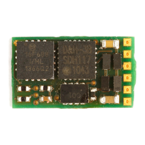
- Page 1 Doehler & Haass LOCOMOTIVE DECODER DH05A/B DH10A/B FH05A...
- Page 2 Loco Decoder DH05A/B Loco Decoder DH10A/B Function Decoder FH05A G1, G2 Track 1, 2 M1, M2 Motor 1, 2 Front light Rear light AUX1, AUX2 Additional functions 1, 2 SUSI supply voltage ZCLK SUSI clock ZDAT SUSI data SUSI ground...
-
Page 3: Table Of Contents
Content Introduction Safety instructions Warranty Support and Help Functions Decoder-Installation Preparation Check after the insertion Installation Operating system SelecTRIX 1 (SX1) Functions Setup features Operation Explication of the signal-stopping section Operating system DCC Functions Setup features Operation Operating system SelecTRIX 2 (SX2) Functions Setup features Operation... -
Page 4: Introduction
FH05A-3 Introduction The locomotive decoder DH05A/B, DH10A/B and FH05A are compatible with the protocols of SelecTRIX Standard SX1 / SX2 as well as with NMRA-DCC-Standard. They can be controlled by every central control unit working with one of these data formats. -
Page 5: Safety Instructions
Safety instructions This product is not suitable for children under 14 years! It might be swallowed by children under 3 years! An improper use involves a risk of injury due to sharp edges and points. Warranty The functioning of every decoder is fully tested before delivery. The warranty period is 2 years from the date of purchase. -
Page 6: Functions
Functions Operation can be controlled either by conventional DC command stations or by digital central units supporting the formats SelecTRIX 1 and 2 or NMRA-DCC Automatically switchover from conventional DC to digital operation In case of digital operation the last programmed system will be activated (no automatically switchover!) ... -
Page 7: Decoder-Installation
Decoder-Installation Preparation Check if the locomotive is in perfect running order electrically and mechanically, prior to any mounting work. Defects and dirt must be eliminated first. Pay attention to the instructions of the locomotive producer. Only locomotives running smoothly in analogue mode, should be equipped with a digital decoder. New locomotives should be run in at least 30 minutes in each direction of travel. -
Page 8: Installation
In case your locomotive is equipped with an interface (NEM 651), you should take the decoder DH05A/B-1, DH10A/B-1 respectively FH05A-1. They have already the appropriate connections for this plug. Shorten the ribbon cable up to approximately 5 mm and remove the rest of the insulation. The decoder can be inserted into the interface without any problem now. - Page 9 Connect the decoder wires accordingly to the following diagram: red wire with the right track wire (G1) black wire with the left track wire (G2) orange wire with the motor wire, which was connected to the right track (M1) gray wire with the motor wire, which was connected to the left track (M2) white wire with the front light (LV)
- Page 10 Function outputs: The function outputs AUX1 and AUX2 are on the underside of the decoder and must be connected to the consumers with individual wires (see Illustration, page 2). Notice: In case of an incorrect wiring of motor, lighting and track, there is no need to solder off the wires as the assignment can be interchanged electronically by programming (see adjustment options of the respective operating system).
-
Page 11: Operating System Selectrix 1 (Sx1)
Operating system SelecTRIX 1 (SX1) Functions Speed steps Speed steps (internal) Front light / rear light Additional functions Additional channel available (Loco address + 1) with 8 additional functions Setup features All locomotive parameters can be varied by programming freely at any time. Please, take the information concerning the programming from the instructions of your programming device. - Page 12 Extended setups Interchange of connections 0 … 7 Activation of AFB and additional channel (A) 1 … 6 Motor regulation variant 1 … 4 AFB ("Automatische Fahr-/Bremssteuerung") = Automatically acceleration / deceleration control Interchange of connections 0 … 7 Interchange motor connections Interchange light connections Interchange track connections Activation of AFB and additional channel...
- Page 13 Reading out the extended characteristic values is executed by the entry of the character sequence 00–111 and a subsequently push on the programming key. Writing of the extended characteristic values is executed by the entry of the character sequence 00=VAI and a subsequently push on the programming key.
-
Page 14: Operation
Operation Put the locomotive on the programming track and read out the programming parameters of the decoder. The default value should be 01-542. Program the desired locomotive address and start running the locomotive keeping the other parameter values. After the first check you can vary the parameters of the engine freely according to your requirements. -
Page 15: Operating System Dcc
Operating system DCC Functions Short addresses 1 – 127 Long addresses 0001 – 9999 Speed steps 14, 28, 126 Speed steps (internal) Front light / rear light (can be dimmed) Additional functions (can be dimmed) Operation with break diodes Operation with break generators Consist mode Full NMRA conform Programming on the main (POM) - Page 16 List of supported CV: Name Definition Range Standard Short address 0 – 127 Starting voltage Minimum speed 0 – 15 Acceleration time The value corresponds to the time 0 – 255 in seconds from start to maximum speed Deceleration time The value corresponds to the time 0 –...
- Page 17 Analog mode FL, F9 – F12 Function Value 0 – 63 FL (f) FL (r) Long address CV17 contains the most significant 0 – 255 byte, CV18 contains the least significant byte, Only if activated by CV29 Consist address Several compound locos run under 0 –...
- Page 18 Consist mode FL, F9 – F12 FL (f) 0 – 63 FL (r) Configuration register Various adjustments 0 – 255 Function Inverse direction 14 ↔ 28/126 speed steps Analog operation permitted Long address by CV17/18 Function mapping F0(f) See supplement 1 0 –...
- Page 19 Function mapping F6 See supplement 1 0 – 255 Function mapping F7 See supplement 1 0 – 255 Function mapping F8 See supplement 1 0 – 255 Function mapping F9 See supplement 1 0 – 255 Function mapping F10 See supplement 1 0 –...
- Page 20 Dimming light "normal" 0 = off … 31 = full brightness 0 – 31 Dimming light "alternative" 0 = off … 31 = full brightness 0 – 31 Dimming AUX1 0 = off … 31 = full brightness 0 – 31 Dimming AUX2 0 = off …...
- Page 21 All configuration variables except for CV01, CV17 and CV18 (= locomotive addresses) can be accessed during operation on your layout (POM / programming on the main).
-
Page 22: Operation
Operation Put the locomotive on the programming track and read out the short locomotive address of the decoder (CV 01). The default value should be 3. Program the desired locomotive address and start running the locomotive keeping the other adjustment values. After the first check you can vary the parameters of the engine freely according to your requirements. -
Page 23: Operating System Selectrix 2 (Sx2)
Operating system SelecTRIX 2 (SX2) Functions Speed steps Speed steps (internal) Front light / rear light (can be dimmed) Additional functions (can be dimmed) Operation with break diodes Programming on the main (POM) Setup features The characteristics of a locomotive operated in the SX2-operating mode can be varied by programming the parameters (par) freely at any time. - Page 24 List of supported parameters: Name Definition Range Standard Loco address unit position 0 – 99 Loco address hundred position 0 – 99 Loco address for SX1 If > 111 deactivated 0 – 255 Additional channel 1 for SX1 Functions F1 – F8 0 –...
- Page 25 Signal-stopping section 1 or 2 0, 1 Consist mode F1 – F8 Reserved Consist mode FL, F9 – F12 Reserved Preclusion for LV Bit 0 = F1 to bit 7 = F8 0 – 255 Preclusion for LR See par024 0 –...
- Page 26 Operating system Occurs during the programming 1, 2, 4 automatically: System Value Characteristic diagram Response curve 0 – 7 0 = linear 7 = logarithmic See supplement 2 Regulation variant 0 = User defined by par056 ff. 0 – 3 1 = Hard 2 = Soft 3 = Very Soft...
- Page 27 Function mapping F1(f+r) See supplement 1 0 – 255 If par063 is written, par075 will be set to the same value Function mapping F2(f+r) See supplement 1 0 – 255 If par064 is written, par085 will be set to the same value Function mapping F3 See supplement 1 0 –...
- Page 28 Dimming AUX1 0 = off … 31 = full brightness 0 – 31 Dimming AUX2 0 = off … 31 = full brightness 0 – 31 Function mapping F2(r) See supplement 1 0 – 255 In case par085 should have another value as par064, you have to set par064 first and then par085...
- Page 29 All parameters except for par001 and par002 (= locomotive address) can be accessed during operation on your layout (POM / programming on the main).
-
Page 30: Operation
Operation Put the locomotive on the programming track and read out the locomotive address of the decoder (par001+par002). The default value should be 1001. Program the desired locomotive address and start running the locomotive keeping the other parameter values. After the first check you can vary the parameters of the engine freely according to your requirements. -
Page 31: Supplement 1
F4 should activate the shunting gear and switch on the outputs LV and LR: LV=1, LR=2, RG=128: so you must enter the value 131 in CV38 | par066. Notice: AUX3 and AUX4 are not available in the decoder DH05A/B DH10A/B and FH05A. Timer function (CV 117 - 120, par076 - 079) - Page 32 Preclusion (CV113 - 116, par024 - 027) This function gives you the option to deactivate a function associated to an output partly (e.g. drivers cab light in front dark), though this output is switched on (e.g. LV by function F0). Example: A typical situation where to apply this function is the push-pull operation.
- Page 33 Supplement 2 Characteristic diagrams Speed step characteristics *) Maximum speed characteristic Characteristic speed step diagram: Linear Logarithmic *) The curve 5 of the speed step characteristics corresponds with the DHL loco decoder series.
- Page 35 Never throw this product in the normal household waste at the end of its lifetime. Please, always use the waste disposal plant of your municipality. Not suitable for children under 36 month because of the danger of swallowing the product and of injuries due to sharp-edged parts. Nicht geeignet für Kinder unter 3 Jahren wegen der Gefahr des Verschluckens sowie der Verletzung durch scharfkantige Teile! Ne convient pas aux enfants en dessous de 36 mois.
- Page 36 Company stamp Doehler & Haass Steuerungssysteme GmbH & Co. KG © 2012 Doehler & Haass GmbH Eichelhäherstrasse 54 Modifications and errors excepted D-81249 München Tel. +49 (0)89 95 47 49 27 technik@doehler-haass.de Version 03/2012 www.doehler-haass.de...
Need help?
Do you have a question about the DH05A/B and is the answer not in the manual?
Questions and answers