Table of Contents
Advertisement
Advertisement
Table of Contents

Related Manuals for Leica OH4


Summary of Contents for Leica OH4
- Page 1 Legal questions / Safety (10 665 629) Service News, Modifications Service Manual Leica OH4 OH4 Stand (10 665 744) Stand for neuro surgical microscopes Doc. Code 10 665742 – 04/2007 Edition 1 User Manual (10 714 367) Installation Manual (10 714...
- Page 3 Leica Microsystems (Schweiz) AG 09/2001 Rechtsfragen/Sicherheit, Legal questions/Safety Inhaltsverzeichnis / Table of contents Kapitel/Chapter Seite/Page Liste der Symbole und deren Bedeutung List of symbols and their meaning Rechtsfragen / Legal questions Sicherheit / Safety Leica Microsystems (Schweiz) AG, Heerbrugg 2001...
- Page 4 Rechtsfragen / Sicherheit, Legal questions / Safety Service manual Leica Microsystems (Schweiz) AG 09/2001 Doc Code 10665629...
- Page 5 Service manual Rechtsfragen / Sicherheit, Legal questions / Safety Doc Code 10665629 Leica Microsystems (Schweiz) AG 09/2001 Liste der Symbole und deren Bedeutung Unmittelbare Gebrauchsgefahr, die zwingend schwere Personenschäden oder den GEFAHR Tod zur Folge hat. Gebrauchsgefahr oder sachwidrige Verwendung, die schwere Personenschäden WARNUNG oder den Tod bewirken kann.
- Page 6 Rechtsfragen / Sicherheit, Legal questions / Safety Service manual Leica Microsystems (Schweiz) AG 09/2001 Doc Code 10665629 List of symbols and their meaning Indicates an imminently hazardous situation which, if not avoided, will result in death DANGER or serious injury.
- Page 7 Mitteln (einschließlich ihrer Umwandlung oder Übertragung in maschinenlesbarer Form) kopiert, in einem Informationsspeicher abgelegt, außerhalb des dafür vorgesehenen Zwecks oder in irgend einer Form an von Leica Microsystems (Schweiz) AG, Heerbrugg nicht ausdrücklich befugte Dritte zugänglich gemacht oder abgegeben werden.
- Page 8 To understand and follow the safety information and instructions on the product, in the user manual and in this Service Manual. • To be familiar with the newest local regulations relating to safety, prevention of accidents and employment security. • To inform Leica Microsystems (Schweiz) AG, Heerbrugg, immediately in writing if the equipment becomes unsafe.
- Page 9 Service manual Rechtsfragen / Sicherheit, Legal questions / Safety Doc Code 10665629 Leica Microsystems (Schweiz) AG 09/2001 Deutsch Leica Microsystems (Schweiz) AG Telefon +41 71 726 33 33 Geschäftseinheit SOM Fax +41 71 726 32 19 Max Schmidheiny-Strasse 201 www.leica-microsystems.com CH-9435 Heerbrugg www.surgicalscopes.com...
- Page 10 Rechtsfragen / Sicherheit, Legal questions / Safety Service manual Leica Microsystems (Schweiz) AG 09/2001 Doc Code 10665629...
- Page 11 Service manual Leica OH4 stand 10 665 744 – Release 04/2007 Table of content 1. Technical Description 2. Wiring Diagram and Locations 3. Service Programs 4. Fault Finding 5. Replacing Modules 6. Maintenance Service 7. Inspection 8. Spare Parts Catalogue...
- Page 12 Releases Leica OH4 Service manual Releases: 04/2007 Edition 1...
- Page 13 Service manual Leica OH4 Technical description Doc. Code 10 665 742 09/2006 3243 GOR 1. Description - Leica OH4 Table of content Chapter Page General Structure of construction Overview system articles Accessories Technical data Principal description Control elements 1-10 Indication operating state...
- Page 14 Technical description Service manual Leica OH4 09/2006 3243 GOR 2-II Doc. Code 10 665 742...
- Page 15 Description of the Leica OH4 General Description The Leica OH4 is a new neuro stand system, consisting of the new OH4 stand system and the existing M525 microscope system. This description will mainly concern the stand system. Service- relevant product improvements...
- Page 16 Technical Description Service manual Leica OH4 9/2006 3243 - GOR Doc. Code 10 665 744 Structure of construction Overview 1 Locking knobs 2 Access hatch 3 Cover for fuses 4 Vertical arm 5 Cover 6 Right handle 7 Optics carrier...
- Page 17 * Standard configuration Generally, accessories from the M525 serial do fit to the OH4 system. CAN handles and footswitches can be assigned individually for each user (see User manual Doc.Code 10 714367, configuration menu, page 48). A mouth switch can be connected as well.
- Page 18 Service manual Leica OH4 9/2006 3243 - GOR Doc. Code 10 665 744 Technical data Electrical data Power connection for Leica M525 OH4: 1600 VA 50/60 Hz 100 V (+10 %/–15 %) 120 V (+10 %/–15 %) 220 V (+10 %/–15 %) 240 V (+10 %/–15 %)
- Page 19 Controls: 10 functions pistol grips for zoom, focus, all-free release of six brakes, side button for user-defined brakes, motorized lateral tilt and inclination (XY) or Leica DI C500 functions. Expect for the all-free button all functions are freely programmable. Mouthswitch for releasing the user defined brakes 12 functions foot control and handswitch.
- Page 20 EN 60601-1; UL60601-1; CAN/CSA-C22.2 NO. 601.1-M90 Electromagnetic compatibility IEC 60601-1-2; EN 60601-1-2 According to the SQS Certificate, the Business Unit SD, within Leica Microsystems (Schweiz) AG, holds the management system certificates for the international standards ISO 9001:2000 / ISO 13485:2003 and ISO 14001:2004 relating to quality management, quality assurance and environmental management.
- Page 21 Service manual Leica OH4 Technical description Doc. Code 10 665 744 09/2006 3243 – GOR Dimensional drawings...
- Page 22 Technical Description Service manual Leica OH4 9/2006 3243 - GOR Doc. Code 10 665 744 Principal description Stand system The stand system is based on the OH3. Improvements and new developments in mechanics and electronics leaded to a better functionality and an easier handling of the stand.
- Page 23 Explanation of luminous energy: The optics of the Leica M525 OH4 surgical microscope have a variable working distance between 207 and 470mm. The system is designed in such a way that it delivers sufficient light to produce a bright image even at a long working distance of 470mm.
- Page 24 9/2006 3243 - GOR 1-10 Doc. Code 10 665 744 Control elements Illumination unit: Main switch power on/off of Leica OH4 system Stand control unit: User interface controlling the microscope system and stand system Pushbutton illumination starting/stopping the Xenon illumination...
- Page 25 Service manual Leica OH4 Technical description Doc. Code 10 665 744 1-11 09/2006 3243 – GOR Indication operating state Illumination unit: Main switch illumination Dark: switched off condition or no AC power connected or defective fuse Shines green: main voltage present at transformer...
- Page 26 Technical Description Service manual Leica OH4 9/2006 3243 - GOR 1-12 Doc. Code 10 665 744...
- Page 27 Service manual Leica M525 OH4 Wiring Doc. Code 10665744 02-I 04/2007 Gahe 02. Wiring diagram - Leica M525 OH4 Table of content Chapter Page Power supply Master controller, DC power unit Master controller, light source Master controller, OH4 adapter, d-axis unit...
- Page 28 Wiring Service manual Leica M525 OH4 04/2007 Gahe 02-II Doc. Code 10665744...
- Page 29 Service manual Leica M525 OH4 Wiring Doc Code 10665744 04/2007 Gahe...
- Page 30 Wiring Service manual Leica M525 OH4 04/2007 Gahe Doc Code 10665744...
- Page 31 Service manual Leica M525 OH4 Wiring Doc Code 10665744 04/2007 Gahe...
- Page 32 Wiring Service manual Leica M525 OH4 04/2007 Gahe Doc Code 10665744...
- Page 33 Service manual Leica M525 OH4 Wiring Doc Code 10665744 04/2007 Gahe...
- Page 34 Wiring Service manual Leica M525 OH4 04/2007 Gahe Doc Code 10665744...
- Page 35 Block diagramm Leica M525 OH4 PCB OH4-1015 C motor limit A/B mode AB balance (axis 4 - local control_1) micro switch 10714786 10714991 10xxxxxx C balance PCB OH4-1016 micro switch 10xxxxxx (swing carrier - local control_2) 10714990 Microscope device controller...
- Page 37 Service manual Leica OH4 Service Programs Doc. Code 10 665744 11/2006 3243 GOR 3. Service Programs - Leica M525 OH4 Control unit Table of content Chapter Page 3.1 Structure of Menu/Service Menu 3.2 How to enter the Service Menu 3.2.1 General Menu Information 3.3 Service Menu for M525 OH4 Control unit...
- Page 38 Service Programs Service manual Leica OH4 11/2006 3243 GOR Doc. Code 10 665 744 3-II...
- Page 39 Service Manual Leica M525 OH4 Control Unit Service Programs and Communications Doc Code 10665744 04/2007 3102-KOJ 3 Service Software for Leica M525 OH4 Control Unit 3.1 Structure of Menu/Service Menu DI C500 Main Page Speed Page Menu Page Help User Settings...
- Page 40 3.2 How to enter the Service Menu 3.2.1 General Menu Information After start up process the Main page is displayed on Leica M525 OH4 Control Unit. There is a quick access button (1) bar to go to the Main-, Speed-, Menu- and Help- pages.
- Page 41 Service Programs and Communications Doc Code 10665744 04/2007 3102-KOJ 3.3 Service Menu for M525 OH4 Control Unit Press “Menu” (1) button in quick access button bar to open Menu page. Press the button “Service Menu” (2) on the “Menu” page.
- Page 42 Service Manual Leica M525 OH4 Control Unit Service Programs and Communications Doc Code 10665744 04/2007 3102-KOJ 3.3.1 Diagnose Menu For downloading diagnostic data to a memory stick insert an USB stick before entering the service button. When the USB stick is recognized by the system you will find a “Download” button on all diagnostic folders.
- Page 43 Service Manual Leica M525 OH4 Control Unit Service Programs and Communications Doc Code 10665744 04/2007 3102-KOJ Use one of the two USB ports to plug in your USB stick. Switch on the microscope. Diagnose folders Click the button “diagnose” to open alle diagnose folders.
- Page 44 Service Manual Leica M525 OH4 Control Unit Service Programs and Communications Doc Code 10665744 04/2007 3102-KOJ Lamp Histroy Select folder “Lamp History” to open a page with hour meters for Lamp 1 (upper lamp) and Lamp 2 (lower lamp). Press “Download” (1) for saving the lamp history data to the file”lamp_history001.txt”...
- Page 45 Service Manual Leica M525 OH4 Control Unit Service Programs and Communications Doc Code 10665744 04/2007 3102-KOJ Press the “Test” (1) or “Adjust” (2)Button . In the chart you will find the testing result of the chosen motor(s). The green check means the tested motor is working faultless.
- Page 46 Service Manual Leica M525 OH4 Control Unit Service Programs and Communications Doc Code 10665744 04/2007 3102-KOJ Press the “Test” button (1). In the chart you will find the testing result of the chosen device(s). The green check means the tested device is working faultless.
- Page 47 Service Manual Leica M525 OH4 Control Unit Service Programs and Communications Doc Code 10665744 04/2007 3102-KOJ Versions Select folder ”Versions” to get an overview of the software and hardware versions of all devices. State 04/07 Device SW Version HW Version...
- Page 48 Service Manual Leica M525 OH4 Control Unit Service Programs and Communications Doc Code 10665744 04/2007 3102-KOJ Press the “Toggle” button (3) the Lamp Performance PopUp (5). A PopUp will inform the user when lamp performance is going down under a certain level. Default setting is “inactive”...
- Page 49 04/2007 3102-KOJ Accessory List Select “Accessory List” folder to activate all device you use with your Leica M525 OH4. Press the “Toggle” button (1) to activate all devices you use. Default settings for all devices is “inactive”. If you activate the FL400 or FL800 device you will have the additional information Whitelight/Bluelight/or NIR Light in the status line.
- Page 50 NTSC. AF Range Parameters: If you use the Autofocus with a Leica M525 OH4 you can only work in the relative mode. Relative Move distance: Set to a value between 1 and 200 mm. Move Type: Set to “Relative” .
- Page 51 Service Manual Leica M525 OH4 Control Unit Service Programs and Communications Doc Code 10665744 04/2007 3102-KOJ 3.3.3 Manuals Click on “Manuals” button to open the “Manuals” page. On this page you can open PDF files with the German and English user manual, the service manual (English only) and the German and English installation manuals.
- Page 52 Service Manual Leica M525 OH4 Control Unit Service Programs and Communications Doc Code 10665744 04/2007 3102-KOJ Operating System Double click the folder “Tools” to open… Tools There are three programs in the folder “Tools”: Calibration Tool OH4 Service Tool Save Registry 3.3.4.1...
- Page 53 Service Manual Leica M525 OH4 Control Unit Service Programs and Communications Doc Code 10665744 04/2007 3102-KOJ Tip in the middle of the crosshairs appearing on the screen. If you use advanced mode there a 9 steps instead of 5 in the standard mode.
- Page 54 OH4 Service Tool Make sure that the you save configurations BEFORE updating any SW – the update procedure will reset all user configurations. Double click on “OH4 Service Tool” icon to start the Leica OH4 Service Tool. Update MDC You can update the software of the Microscope Device Controller (MDC).
- Page 55 Service Manual Leica M525 OH4 Control Unit Service Programs and Communications Doc Code 10665744 04/2007 3102-KOJ A dialog window “Select SRrec-File…” shows up. Double click on folder “UpdateMDC” Double click on the “OH4MDC.exe” file to start the updating process. Progress bar gives you information about the progress of updating process.
- Page 56 Service Manual Leica M525 OH4 Control Unit Service Programs and Communications Doc Code 10665744 04/2007 3102-KOJ Update UIC Press button “Update UIC” to update user interface controller. A dialog window “Select UIC Application” shows up. Double click on “UpdateUIC” Double click on the “OH4UIC.exe” file to start the updating process.
- Page 57 Service Manual Leica M525 OH4 Control Unit Service Programs and Communications Doc Code 10665744 04/2007 3102-KOJ Confirm with “Yes to All”. Progress bar gives you information about the progress of updating process. Update OH4 Adapter Click on “Update OH4 Adapter” to start update process. 3-19...
- Page 58 Service Manual Leica M525 OH4 Control Unit Service Programs and Communications Doc Code 10665744 04/2007 3102-KOJ Click on “Update OH4 Adapter”. A dialog window “Select Hex-File…” shows up. Double click on folder “UpdateOH4Adapter” Double click on the “OH4_Adapter V1_x.hex” file to start the updating process.
- Page 59 Service Manual Leica M525 OH4 Control Unit Service Programs and Communications Doc Code 10665744 04/2007 3102-KOJ Save / Restore Configuration You can save the user settings of all 30 users that can be created and stored in the user list in the control unit to an USB stick.
- Page 60 Service Manual Leica M525 OH4 Control Unit Service Programs and Communications Doc Code 10665744 04/2007 3102-KOJ The following files including up to 30 user settings (user1.ini to user30.ini) will be created in the folder “OH4SavedConfig” . Install/Update HowTo Bitmaps Make sure that an USB stick is plugged in (see chapter 3.35 on page 3-25).
- Page 61 Service Manual Leica M525 OH4 Control Unit Service Programs and Communications Doc Code 10665744 04/2007 3102-KOJ Install/Update PopUps Make sure that the folder “OH4UpdatePopUp” is on the USB stick. Click on “Install / Update Manuals”. Confirm with “yes’. Progress bar gives you information about the progress of updating process.
- Page 62 Service Manual Leica M525 OH4 Control Unit Service Programs and Communications Doc Code 10665744 04/2007 3102-KOJ Factory Settings Press “Factory Settings” to start reset to factory settings process. For a proper termination of SW updates you MUST perform this procedure! Confirm with “Yes”...
- Page 63 Service Manual Leica M525 OH4 Control Unit Service Programs and Communications Doc Code 10665744 04/2007 3102-KOJ Exit Updater Click on “Exit Updater” to exit the Leica OH4 Service tool. Always proceed with “Save Registry” to save all changes permanently in the operating system. Save Registry To save your changes permanently in the operating system double click on the “Save...
- Page 64 Service Manual Leica M525 OH4 Control Unit Service Programs and Communications Doc Code 10665744 04/2007 3102-KOJ Create the following folders on your USB stick: \OH4UpdateHowTo \OH4UpdateManuals \OH4UpdatePopUp \OH4SavedConfig \OH4DemoUser and copy all necessary files to these folders (see description below).
- Page 65 Service Manual Leica M525 OH4 Control Unit Service Programs and Communications Doc Code 10665744 04/2007 3102-KOJ Content of the folder “OH4UpdatePopUp” Content of the folder “UpdateUIC” (or in root directory) Content of the folder “UpdateOH4Adapter” 3-27...
- Page 66 Service Manual Leica M525 OH4 Control Unit Service Programs and Communications Doc Code 10665744 04/2007 3102-KOJ Content of the folder “UpdateMDC” Content of the folder “SavedConfig” -> create an empty folder with the name “SavedConfig” . Files will be written to this folder when you are saving the configuration.
- Page 67 Service Manual Leica M525 OH4 Control Unit Service Programs and Communications Doc Code 10665744 04/2007 3102-KOJ Unscrew and remove fan holder plate. Unplug fan. Plug in the USB stick into any of the two USB connectors. Switch on again the Leica M525 OH4 The USB stick will be recognized by the system.
- Page 68 Service Manual Leica M525 OH4 Control Unit Service Programs and Communications Doc Code 10665744 04/2007 3102-KOJ Double click on your “USB Stick”. You will see the content of your USB stick. Open the folder “UpdateServiceTool” by double clicking. Double click on the batch file “Update Service Tool”.
- Page 69 Service manual Leica OH4 stand Replacing modules/adjusting procedures Doc. Code 10665744 04/2007 3243 - GOR 5. Replacing modules/adjusting procedures Table of content Chapter Page D-balance adjustment A/B-balance adjustment Check/adjust C-arm backlash 5-21 Adjust C-arm backlash with shim set 5-23...
- Page 70 Replacing modules/adjusting procedures Service manual Leica OH4 stand 04/2007 3243 - GOR 5-II Doc. Code 10665744...
- Page 71 Service manual Leica OH4 Replacing modules/adjusting procedures Doc. Code 10665744 04/2007 GOR 5 Replacing modules/adjustment procedures D-balance module (Mitaka procedure) 1. Turn on the main power and adjust balance correctly by using manual switch. 2. Remove 2 covers, please make switch and switch LED visible (refer to picture 1, 2 & 3).
- Page 72 Replacing modules/adjusting procedures Service manual Leica OH4 04/2007 GOR Doc. Code 10665744 switch switch Picture 3...
- Page 73 Service manual Leica OH4 Replacing modules/adjusting procedures Doc. Code 10665744 04/2007 GOR 3. If the D-axis is moved up and down by the hand, confirm the LEDs blink in order. 4. If LED has blinked quickly in order, it is no problem for the balance switch.
- Page 74 Replacing modules/adjusting procedures Service manual Leica OH4 04/2007 GOR Doc. Code 10665744 7. When not becoming it as shown in the picture 4, 5, “Thread locker” of the switch screw and the fixation screw for switch screw are removed by using the solvent (organic solvent etc). (...
- Page 75 Service manual Leica OH4 Replacing modules/adjusting procedures Doc. Code 10665744 04/2007 GOR 8. Perfect switch adjustment is only one LED will light if you insert the 0.05mm shim and push down the D-axis, LED will not light if you removed shim. The fixation screw for switch screw is loosened with 1.5 mm hexagonal wrench, the switch screw moves with 2mm hexagonal wrench and it adjusts, then the switch fixation screw for switch screw is tightened with 1.5mm wrench.
- Page 76 Replacing modules/adjusting procedures Service manual Leica OH4 04/2007 GOR Doc. Code 10665744 0.05mm Picture9...
- Page 77 Service manual Leica OH4 Replacing modules/adjusting procedures Doc. Code 10665744 04/2007 GOR 9. Implement the same adjustment with 0.10mm shim. In this case, both LEDs will light. (refer to picture 10,11,12) With 2mm wrench With 1.5mm wrench Picture10 Picture11 0.10mm...
- Page 78 Replacing modules/adjusting procedures Service manual Leica OH4 04/2007 GOR Doc. Code 10665744 10. If the D-axis is moved up and down by the hand, confirm the LEDs blinks in order. 11. “Thread locker” is spread on the switch screw and the fixation screw for switch screw.
- Page 79 Service manual Leica OH4 Replacing modules/adjusting procedures Doc. Code 10665744 04/2007 GOR A/B-balance module (Mitaka procedure) 1. Turn on the main power and adjust all balance correctly by using manual switch at each axis...
- Page 80 Replacing modules/adjusting procedures Service manual Leica OH4 04/2007 GOR 5-10 Doc. Code 10665744 2. Remove 3 covers, please make switch and switch LED visible (refer to pictures below).
- Page 81 Service manual Leica OH4 Replacing modules/adjusting procedures Doc. Code 10665744 5-11 04/2007 GOR...
- Page 82 Replacing modules/adjusting procedures Service manual Leica OH4 04/2007 GOR 5-12 Doc. Code 10665744 switch switch...
- Page 83 Service manual Leica OH4 Replacing modules/adjusting procedures Doc. Code 10665744 5-13 04/2007 GOR...
- Page 84 Replacing modules/adjusting procedures Service manual Leica OH4 04/2007 GOR 5-14 Doc. Code 10665744 3. It lightly touches the microscope etc. by the finger, whether LED blinks alternately is confirmed applying by the light power (0.1N*m). (Confirm it respectively in a state both position A and B).
- Page 85 Service manual Leica OH4 Replacing modules/adjusting procedures Doc. Code 10665744 5-15 04/2007 GOR 6. The part in the picture is a gap part for the switch perceives. Insert shim of 0.03mm in this gap. LED lights respectively if it is normal.
- Page 86 Replacing modules/adjusting procedures Service manual Leica OH4 04/2007 GOR 5-16 Doc. Code 10665744 0.03mm 0.03mm...
- Page 87 Service manual Leica OH4 Replacing modules/adjusting procedures Doc. Code 10665744 5-17 04/2007 GOR 7. When not becoming it as shown in the picture of 6, “Thread locker” of the switch and the switch fixation screw are removed by using the solvent (organic solvent etc).
- Page 88 Replacing modules/adjusting procedures Service manual Leica OH4 04/2007 GOR 5-18 Doc. Code 10665744 8. Perfect switch adjustment is that LED will light if you insert the shim, LED will not light if you removed shim. The switch fixation screw is loosened with 2 mm hexagonal wrench, it moves while rotating the switch and it adjusts, then the switch fixation screw is tightened (The switch reacts when 20µm moves after touching by the point.
- Page 89 Service manual Leica OH4 Replacing modules/adjusting procedures Doc. Code 10665744 5-19 04/2007 GOR 9. Implement the same adjustment for the other side. 10. Confirm whether LED is blinked at A and B position by light power.
- Page 90 Replacing modules/adjusting procedures Service manual Leica OH4 04/2007 GOR 5-20 Doc. Code 10665744 11. “Thread locker” is spread on the switch and the switch fixation screw. 12. Each cover is tightened. (4 pcs screws in the picture are tightened equivalently)
- Page 91 Service manual Leica OH4 Replacing modules/adjusting procedures Doc. Code 10665744 5-21 04/2007 GOR Check/adjust of C-arm backlash (Mitaka procedure) Checking screws At first remove the clutch (No. 4) cover, and please confirm that a screw of an arrow of picture below tightens surely.
- Page 92 Replacing modules/adjusting procedures Service manual Leica OH4 04/2007 GOR 5-22 Doc. Code 10665744 When there is still backlash, there is a possibility that engaging the worm gear loosens. Please adjust engaging according to the following instructions. Please perform its clamping work and confirmation of backlash after balancing of microscope.
- Page 93 Service manual Leica OH4 Replacing modules/adjusting procedures Doc. Code 10665744 5-23 04/2007 GOR Adjusting by shim set 10714998 1. Turn off main power 2. Remove cover at brake 5 3. Hold both hand grips and tilt microscope either right or left. Confirm A and B move independently – refer to...
- Page 94 Replacing modules/adjusting procedures Service manual Leica OH4 04/2007 GOR 5-24 Doc. Code 10665744 4. Apply grease (FM5 - 10289967 or similar) to both sides of the 2 spacers, then insert these between B and C until it flushes with B.
- Page 95 • Slides, sliding parts - use Leica grease D2 (number for 25g – 10289966) • Screws- use Leica grease FM5 (number for 25g – 10289967) • Worm gear drive (D-balance) – use Leica grease (10128392 Molykote G Rapid PL) grease 10128392 D-balance...
- Page 96 Maintenance service Service manual Leica OH4 stand 04/2007 3243 - GOR Doc. Code 10 665 744...
- Page 97 Service manual Leica OH4 stand Inspection Doc. Code 10 665 744 04/2007 3243 GOR 7. Inspection - Leica OH4 stand Table of content Chapter Page Test certificate List of accessories and their weight Leakage current test...
- Page 98 Inspection Service manual Leica OH4 stand 04/2007 3243 GOR 7-II Doc. Code 10 665 744...
- Page 99 Service manual Leica OH4 stand Inspection Doc. Code 10 665 744 04/2007 3243 - GOR Test Certificate for Leica OH4 stand Configuration: System Serial no. Software version Remark Stand OH4 Stand: Stand: Microscope system Optics carrier: Optics carrier: M525 OH4...
- Page 100 Inspection Service manual Leica OH4 stand 04/2007 3243 GOR Doc. Code 10 665 744 List of accessory and its weight Attached Accessory Stock nbr. Single weight Total weight Eyepiece f. spect. W’s 10x/21B 10446485 0.1 kg Binocular tube variable 30-150°...
- Page 101 Service manual Leica OH4 stand Inspection Doc. Code 10 665 744 04/2007 3243 - GOR Leakage Current Test related to IEC 601-1 Description Permitted value Actual value < 200 µA (220/240V) µA Stand + main Xenon lamp < 200 µA (220/240V) µA...
- Page 102 Inspection Service manual Leica OH4 stand 04/2007 3243 GOR Doc. Code 10 665 744...
- Page 103 Service manual Leica OH4 Spare parts catalogue Doc Code 10665744 04/2007 GOR/GAHE Spare parts – OH4 Table of content Chapter Page General parts Base Tower/Column Light source Control unit 8-10 D-balance module 8-13 Swing arm large 8-15 Swing carrier 8-17...
- Page 104 Spare parts catalogue Service manual OH4 04/2007 GOR/GAHE Doc Code 10665744 Stock n° Description / Specification Remark Drawing 8-II...
- Page 105 Spare parts catalogue Doc Code 10665744 04/2007 GOR/GAHE Stock n°. Description / Specification Remark Drawing Spare parts – OH4 General parts 10714718 Set of screws contains: 6 x M3x25 Cap Screws 4 x M3x8 Cap Screws 3 x M5x15 Cap Screws...
- Page 106 Spare parts catalogue Service manual OH4 04/2007 GOR/GAHE Doc Code 10665744 Stock n° Description / Specification Remark Drawing 10182490 Power cable 5m CH 10445664 Power cable 5m USA 10445665 Power cable 5m EU 10445666 Power cable 5m BS 10280636 Power cable 2.5m CH 10445661 Power cable 2.0 m US...
- Page 107 Service manual OH4 Spare parts catalogue Doc Code 10665744 04/2007 GOR/GAHE Stock n°. Description / Specification Remark Drawing Base 10714720 Base complete delivery time on request 10714721 Castor 10714722 Damper for castor 10714723 Nut set for castor self locking nut M10 SW17...
- Page 108 Spare parts catalogue Service manual OH4 04/2007 GOR/GAHE Doc Code 10665744 Stock n° Description / Specification Remark Drawing 10714725 Lock pedal delivery time on request 10711946 Blue damper for brake 1,3 like OH3 10714726 Fan for DC power module/Xenon power supply...
- Page 109 Service manual OH4 Spare parts catalogue Doc Code 10665744 04/2007 GOR/GAHE Stock n°. Description / Specification Remark Drawing Tower/Column 10714727 Transformer unit complete delivery time on request 10714728 Transformer (100-240V out) delivery time on request 10714729 Transformer (36V out) delivery time on request...
- Page 110 Spare parts catalogue Service manual OH4 04/2007 GOR/GAHE Doc Code 10665744 Stock n° Description / Specification Remark Drawing 10711983 Power inlet like OH3: type SW2A2 & SW950A1 10714731 Main line filter type SUP-P15H-R-0 10714732 Line filter Xenon & AC outlet type SUP-P10H-R-0...
- Page 111 Service manual OH4 Spare parts catalogue Doc Code 10665744 04/2007 GOR/GAHE Stock n°. Description / Specification Remark Drawing Tower/Column – light source 10714734 Light source complete (bulbs not included) 10714734R Light source complete – replacement part 10714735 Motor for lamp change...
- Page 112 Attenuation filter 10711989 Fan for Xenon bulb like OH3: MD925A-24L: with built-in sensor 10714726 Fan for DC power module/Xenon power supply MD925A-24; with 2 pole connector 10714742 PCB OH4 1012 ( Lamp ON/OFF board) 10714743 PCB OH41021 (Filter wheel board)
- Page 113 Service manual OH4 Spare parts catalogue Doc Code 10665744 04/2007 GOR/GAHE Stock n°. Description / Specification Remark Drawing 10714744 PCB OH41022 (Attenuator board) 10448022 Xenon lamp 10712861 Xenon power module LMS supply...
- Page 114 10714747 Switch for lamp and autobalance 10714123 OH4 control unit frame, display and PC 10714123R OH4 control unit – replacement part 10714124 Display 10.4” with touch panel 10714582 Flash card with latest SW (10714581) available after next SW-release (appr. May 2007)
- Page 115 Service manual OH4 Spare parts catalogue Doc Code 10665744 04/2007 GOR/GAHE Stock n°. Description / Specification Remark Drawing 10714748 PCB OH41014 (master controller) 10714127 OH4 adapter 10714130 MDC Microscope device controller (HW like M844!) 10714132 SVGA switch board 10714749 DC12V output plug...
- Page 116 Spare parts catalogue Service manual OH4 04/2007 GOR/GAHE Doc Code 10665744 Stock n° Description / Specification Remark Drawing 10714133 Standard connector board LMS supply 10714751 Bracket for standard connector board delivery time on request 10714752 Fan for tower ventilation MD825B-24, with connector...
- Page 117 Service manual OH4 Spare parts catalogue Doc Code 10665744 04/2007 GOR/GAHE Stock n°. Description / Specification Remark Drawing D-balance module 10714756 cover for D-balance module delivery time on request 10714757 D-balance motor type SS23F 10714758 Set of belts for D-balance...
- Page 118 Spare parts catalogue Service manual OH4 04/2007 GOR/GAHE Doc Code 10665744 Stock n° Description / Specification Remark Drawing 10714760 Fixed weight (rear) delivery time on request 10714761 Fixed weight (front) including o-ring and warning labels delivery time on request 10714762...
- Page 119 Service manual OH4 Spare parts catalogue Doc Code 10665744 04/2007 GOR/GAHE Stock n°. Description / Specification Remark Drawing Swing arm large 10714766 Front cover including 2x Allen screw M3x20 delivery time on request 10714767 Rear cover including 2x Allen screw M3x30...
- Page 120 Spare parts catalogue Service manual OH4 04/2007 GOR/GAHE Doc Code 10665744 Stock n° Description / Specification Remark Drawing 10712016 Cap for horizontal arm like OH3 10712015 damper horizontal arm like OH3 10714771 Brake 4 unit delivery time on request 10714772...
- Page 121 Service manual OH4 Spare parts catalogue Doc Code 10665744 04/2007 GOR/GAHE Stock n°. Description / Specification Remark Drawing Swing carrier 10714773 Swing carrier complete unit 10714773R Swing carrier complete unit; exchange part 10714774 A slide module delivery time on request...
- Page 122 Spare parts catalogue Service manual OH4 04/2007 GOR/GAHE Doc Code 10665744 Stock n° Description / Specification Remark Drawing 10714778 Upper cover including 2x Allen screw M3x32 delivery time on request 10714779 Cover at brake 5 including 2x countersunk screw M3x10 Cover at brake 5 –...
- Page 123 Service manual OH4 Spare parts catalogue Doc Code 10665744 04/2007 GOR/GAHE Stock n°. Description / Specification Remark Drawing 10714783 C axis balance micro switch including 0.03 mm shim set of 2: 10714786 PCB OH41015 (axis 4) 10714787 PCB OH41016 (swing arm small)
- Page 124 Belt for motor A or B like OH3: S2M134 10712028 Switch for manual balance like OH3 (axis A, B, or C) 10712029 Switch for A/B position detection like OH3 10714785 PCB OH41017 ( A slide) 10714788 PCB OH4 1018A (B slide) 8-20...
- Page 125 Service manual OH4 Spare parts catalogue Doc Code 10665744 04/2007 GOR/GAHE Stock n°. Description / Specification Remark Drawing Handgrip 10714791 Handgrip left, complete with cable (without joint) 10714792 Handgrip right, complete with cable (without joint) 10711939 joystick for handgrip like OH3...
- Page 126 Spare parts catalogue Service manual OH4 04/2007 GOR/GAHE Doc Code 10665744 Stock n° Description / Specification Remark Drawing 10711940 Handgrip joint left like OH3 delivery time on request 10711941 Handgrip joint right like OH3 10711942 Lever 1 for handgrip like OH3 incl.
- Page 127 Service manual OH4 Spare parts catalogue Doc Code 10665744 04/2007 GOR/GAHE Stock n°. Description / Specification Remark Drawing 10710090SP Push button switch without button like OH3 10714793 Cover type nut for switches (long) 10714794 Cover type nut for switches (short)
- Page 128 Spare parts catalogue Service manual OH4 04/2007 GOR/GAHE Doc Code 10665744 Stock n° Description / Specification Remark Drawing Optics carrier M525 OH4 10448238R Optics carrier M525 OH4 exchange part 8-24...
- Page 129 Service manual OH4 Spare parts catalogue Doc Code 10665744 04/2007 GOR/GAHE Stock n°. Description / Specification Remark Drawing Cable 10714985 delivery time on request 10714986 delivery time on request 8-25...
- Page 130 Spare parts catalogue Service manual OH4 04/2007 GOR/GAHE Doc Code 10665744 Stock n° Description / Specification Remark Drawing 10714987 delivery time on request 10714988 8-26...
- Page 131 Service manual OH4 Spare parts catalogue Doc Code 10665744 04/2007 GOR/GAHE Stock n°. Description / Specification Remark Drawing 10714989 10714990 8-27...
- Page 132 Spare parts catalogue Service manual OH4 04/2007 GOR/GAHE Doc Code 10665744 Stock n° Description / Specification Remark Drawing 10714991 10714999 04/2007: delivery time on request, later ex stock 8-28...
- Page 133 Service manual OH4 Spare parts catalogue Doc Code 10665744 04/2007 GOR/GAHE Stock n°. Description / Specification Remark Drawing 10xxxxxx not supplied for info only 10xxxxxx not supplied for info only 8-29...
- Page 134 Spare parts catalogue Service manual OH4 04/2007 GOR/GAHE Doc Code 10665744 Stock n° Description / Specification Remark Drawing 10714992 10715051 04/2007: delivery time on request, later ex stock 8-30...
- Page 135 Service manual OH4 Spare parts catalogue Doc Code 10665744 04/2007 GOR/GAHE Stock n°. Description / Specification Remark Drawing 10714993 10714994 delivery time on request 8-31...
- Page 136 Spare parts catalogue Service manual OH4 04/2007 GOR/GAHE Doc Code 10665744 Stock n° Description / Specification Remark Drawing 10714995 D-balance cable 10xxxxxx 04/2007: delivery time on request, later ex stock 8-32...
- Page 137 Description / Specification Remark Drawing lenght = 470mm Data cable CAN MDC-OH4 adapter 10714136 lenght = 820mm 10714138 Data cable OH4 adapter – SVGA switch board lenght = 885mm switch board Data cable MDRS to OH4 SVGA switch board 10714595 8-33...
- Page 138 Service manual OH4 04/2007 GOR/GAHE Doc Code 10665744 Stock n° Description / Specification Remark Drawing Data cable RS232 CU - MDC 10714134 Data cable RS232 CU – OH4 adapter 10714135 delivery time on request Power cable for control unit 10714579 8-34...
- Page 139 Service manual OH4 Spare parts catalogue Doc Code 10665744 04/2007 GOR/GAHE Stock n°. Description / Specification Remark Drawing Internal power distribution: 10712674 Power cable for. multi socket 10714455 DC Power Cable for MDRS final drawings not ready yet in PLM: Thm 10714602 DC Power cable for Monitor 19"...
- Page 140 Spare parts catalogue Service manual OH4 04/2007 GOR/GAHE Doc Code 10665744 Stock n° Description / Specification Remark Drawing Tools 10714769 Download cable for master control software 10714583 USB stick OH4 Software 10712148 CAN cable for test purpose 8-36...
- Page 141 Leica M525 OH4 User manual 10 714 367 – version -...
- Page 142 Thank you for choosing our products. We hope that you will enjoy the quality and performance of your Leica Microsystems surgical microscope. Leica Microsystems (Schweiz) AG Surgical Microscopy Business Unit Leica M525 OH4 / Ref. 10 714 367 / Version -...
- Page 143 Chapter overview Introduction Controls Preparation for operation Safety notes Care and maintenance What to do if...? Technical data Leica M525 OH4 / Ref. 10 714 367 / Version -...
- Page 144 Dimensional drawings Positioning the microscope Adjusting the microscope Control unit with touch panel Leica DI C500 Autofocus settings The Maintenance menu Microscope settings The "How to..." menu The Service menu Leica M525 OH4 / Ref. 10 714 367 / Version -...
- Page 145 Useful information that can help the user have. operate the product correctly and efficiently. Model: Serial No.: ➩ Call to action; here you are asked to do - something. Leica M525 OH4 / Ref. 10 714 367 / Version -...
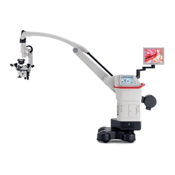
- Page 146 1 Swing arm 2 Tiebar 3 Video monitor (optional) 4 Control unit with touch panel 5 Suspension device for footswitch 6 Illumination unit 7 Base 8 Optical carrier Leica M525 Leica M525 OH4 / Ref. 10 714 367 / Version -...
- Page 147 6 Camera control unit (optional) 7 System unit Leica MDRS3 (optional) The Leica M525 with its open architecture, offers space for accommodating the video control unit and the Leica MDRS3. Leica M525 OH4 / Ref. 10 714 367 / Version -...
- Page 148 20 Reset button for zoom dependent illumination field diameter 13 B-carriage adjustment 14 Swing mount 21 Status of multifocus LED 22 Multifocus key 23 Rotary button for focus adjustment 24 Working distance display Leica M525 OH4 / Ref. 10 714 367 / Version -...
- Page 149 26 Ethernet adapter Terminals 24, 25 and 26 are adapters which can be used to lead out the terminals of the optional Leica MDRS3 system unit or a camera control. Leica M525 OH4 / Ref. 10 714 367 / Version -...
- Page 150 2 Access door 3 Screw knob 4 Master switch for Leica M525 OH4 surgical microscope 5 Selector switch 100V/120V/220V/240V 6 Power supply 7 Potential equalization socket 8 Fuse box flap Leica M525 OH4 / Ref. 10 714 367 / Version -...
- Page 151 (see page 50). Footswitch Here you will find an overview of the footswitches which you can use to control your Leica M525 surgical microscope. Footswitches can be assigned individually for each user in the configuration menu (see page 48). Footswitch...
- Page 152 Zoom - Focus - Focus - All Brakes All Brakes Selected brakes Selected brakes Focus + Focus - No function No function No function No function Zoom + Zoom - Leica M525 OH4 / Ref. 10 714 367 / Version -...
- Page 153 Zoom - Focus - Focus - All Brakes All Brakes Selected brakes Selected brakes Focus + Focus - IGS 3 IGS 2 IGS 4 IGS 1 Zoom + Zoom - Leica M525 OH4 / Ref. 10 714 367 / Version -...
- Page 154 Focus - All Brakes All Brakes Selected brakes Selected brakes Focus + Focus - DI C500: DI C500: Display on/off Shutter control No function No function Zoom + Zoom - Leica M525 OH4 / Ref. 10 714 367 / Version -...
- Page 155 Focus - All Brakes All Brakes Selected brakes Selected brakes Focus + Focus - FL800 Mode on/off FL800 NIR Zoom Reset MDRS3 FL:Menu&Down MDRS3 FL: Playback&Enter Zoom + Zoom - Leica M525 OH4 / Ref. 10 714 367 / Version -...
- Page 156 Focus - Focus - All Brakes All Brakes Selected brakes Selected brakes Focus + Focus - FL400 Mode on/off No function No function No function Zoom - Zoom + Leica M525 OH4 / Ref. 10 714 367 / Version -...
- Page 157 FL400 Mode on/off Selected brakes IGS 3 IGS 4 IGS 2 Focus + Focus - FL400 Mode on/off No function No function No function Zoom + Zoom - IGS 1 Leica M525 OH4 / Ref. 10 714 367 / Version -...
- Page 158 FL800 NIR Zoom Reset MDRS3 FL: Playback&Enter FL400 Mode on/off Focus + Focus - No function FL400 Mode on/off No function No function Zoom - Zoom + MDRS3 FL: Menu&Down Leica M525 OH4 / Ref. 10 714 367 / Version -...
- Page 159 Surgeon (front) 40% (stereo) Assistant (rear) 40% (stereo) or Assistant (side) 40% (mono) Documentation (side) 20% • Can be used for co-observation or documentation Light distribution: 50% on each side (mono) Leica M525 OH4 / Ref. 10 714 367 / Version -...
- Page 160 • Beam splitter with eight optical ports • Integrated color display shows data or video images. • Light distribution: Surgeon (front) 40% (stereo) Assistant (rear) 40% (stereo) or Assistant (side) 40% (mono) Documentation (side) 20% Leica M525 OH4 / Ref. 10 714 367 / Version -...
- Page 161 • Variable viewing angles from 30° to 150° • Adjustable viewing height • Adjustable interpupillary distance Binocular tube variable from 0°–180° Inclined binocular tube 45° • Variable viewing angles from 0° to 180° Leica M525 OH4 / Ref. 10 714 367 / Version -...
- Page 162 • Adapter f = 350mm: for high magnifications. • The phototube (6) is mounted on the documentation port of the 0° assistant’s attachment. Leica M525 OH4 / Ref. 10 714 367 / Version -...
- Page 163 ➩Remove dust and dirt (see page 68). ➩Fit sterile components and sterile drape if used (see page 36). Installing accessories ➩Lock the Leica M525 OH4 in place and install all accessories Warning 2 Danger of fatal electric shock on the microscope so it is ready for use (see page 22).
- Page 164 ➩Do not release the brakes when the instrument is in an unbalanced state. Locking the Leica M525 OH4 in position The D-axis of the Leica M525 OH4 is locked in position with the locking device. The locking device is principally for installation and ➩Release the clamping screw (3).
- Page 165 The acquired value (2) can be stored for each user on the "User Settings" menu screen under "Tube Settings" (see page 51). Adjusting the tilt ➩Hold the tube with both hands. ➩Tilt the tube up or down. Leica M525 OH4 / Ref. 10 714 367 / Version -...
- Page 166 4 Camera adapter 5 Photo camera and photo lens The object image at the camera output is laterally reversed! ➩Rotate the eyecups up or down until the desired distance is set. Leica M525 OH4 / Ref. 10 714 367 / Version -...
- Page 167 ➩Set the maximum magnification (f=100) on the Zoom Video Adapter. ➩Focus the monitor image on the Zoom Video Adapter. Adjusting the magnification Focusing knob ➩Set the desired magnification on the Zoom Video Adapter. Leica M525 OH4 / Ref. 10 714 367 / Version -...
- Page 168 85mm 100mm 107mm 1/4 “ 1/3 “ 1/2 “ 2/3 “ 1 “ Photo/TV dual attachment 250 mm 350 mm 35 mm Digital Photo Field of view Camera Monitor/image Leica M525 OH4 / Ref. 10 714 367 / Version -...
- Page 169 ➩Press the "All Brakes" button on the CAN handle and move the optical carrier into the A-position. The mark (1) musty be pointing to A. The balancing procedure can be canceled at any time using "Interrupt Balancing". Leica M525 OH4 / Ref. 10 714 367 / Version -...
- Page 170 (can be deactivated in the service menu). ➩Acknowledge with the "Close" button. ➩Correct the alignment of the optical carrier (A-position). ➩Press push-button (2). Autobalancing re-starts. Leica M525 OH4 / Ref. 10 714 367 / Version -...
- Page 171 5 seconds. ➩Check the balancing. ➩Press the "All Brakes" button on the CAN handle and position the microscope. The microscope must remain fixed in any position. Leica M525 OH4 / Ref. 10 714 367 / Version -...
- Page 172 The mark (3) must be pointing towards B. ➩Press the "All Brakes" button on the CAN handle and move the optical carrier into the A-position. The mark (2) must be pointing towards A. Leica M525 OH4 / Ref. 10 714 367 / Version -...
- Page 173 ➩Check the balancing. ➩Press the "All Brakes" button on the CAN handle and position the microscope. The microscope must remain fixed in any position. ➩Correct the balancing, if necessary. Leica M525 OH4 / Ref. 10 714 367 / Version -...
- Page 174 (see page 80). The optical carrier (in the A-position) tilts back: ➩Move the A-axis forwards with switch (2) until the optical carrier is balanced. Leica M525 OH4 / Ref. 10 714 367 / Version -...
- Page 175 To balance the D-axis when using accessories with dif- ferent weights, the number of D-axis weight disks can be adapted accordingly (see below). Leica M525 OH4 / Ref. 10 714 367 / Version -...
- Page 176 Preparation for operation ➩Unscrew the hexagon nut (3). Changing the weight disk on the D-axis If the Leica M525 OH4 cannot balance the accessories in use, a weight disk must be added to or removed from the D-axis. Caution 1 Danger of injury due to falling weight disk or cover! ➩When changing the weight disk, make sure that your...
- Page 177 The button for the selected brake combination lights up green. You can save the desired brake combination individually for each user in the user settings in the "Start Values Speed" menu. Leica M525 OH4 / Ref. 10 714 367 / Version -...
- Page 178 ➩Never move the stand in the extended condition. ➩Never roll over cables lying on the floor. ➩Press the "All Brakes" button and move the Leica M525 OH4 into the transport position (see illustration below). ➩Pull the protective cover over the Leica M525 OH4.
- Page 179 ➩Fit steam-sterilizable covers on the light field diameter adjust- unbalanced state. ment knob and the working distance adjustment knob. The Leica M525 OH4 can be positioned easily on the operating table and offers a variety of possibilities for operations on the head or spinal column.
- Page 180 This value can be saved individually for each user ➩Insert the protective glass upwards into the bayonet mount in (see page 46). direction (a). ➩Turn the protective glass in direction (b) until it engages. Leica M525 OH4 / Ref. 10 714 367 / Version -...
- Page 181 Explanation of luminous energy: The optics of the Leica M525 OH4 surgical microscope have a variable working distance of between 207 and 470mm. The sys- tem is designed in such a way that it delivers sufficient light to produce a bright image even at a long working distance of 470mm.
- Page 182 This safety function can be deactivated by clicking the "Brightcare™" button. A dialog window opens in which you have to confirm that you want to deactivate the safety function. Leica M525 OH4 / Ref. 10 714 367 / Version -...
- Page 183 Changing over to backup illumination ➩Undo screw knob (3) and open the access door (2) for lamp inserts on the illumination unit. The push-button (1) flashes orange. Leica M525 OH4 / Ref. 10 714 367 / Version -...
- Page 184 OP lamp can be used for better illumination of a large visual field (low zoom setting). ➩Hold down rotary button (3). ➩Set the desired magnification by turning the knob. Leica M525 OH4 / Ref. 10 714 367 / Version -...
- Page 185 The yellow LED (4) goes out and the focus is released. Warning 10 Danger to patient due to failure of the zoom motor! ➩In case of failure of the zoom motor, the zoom can be adjusted manually. Leica M525 OH4 / Ref. 10 714 367 / Version -...
- Page 186 3 Status line 4 Display range 5 Dynamic button bar In operational mode, the status bar displays the current user and specifies the current location in the menu at all times. Leica M525 OH4 / Ref. 10 714 367 / Version -...
- Page 187 "Presets", "User List" and "Show Settings". Click the "1-15" or "16-30" button to switch between screens. You can find a list of default users preset by Leica for the most ➩Select user and click "Select". common types of operation under "Presets".
- Page 188 ("Save") or under a new username ("Save as"). Leica M525 OH4 / Ref. 10 714 367 / Version -...
- Page 189 The "WD-Reset" function is activated, the "WD-Reset" button changes color form gray to green. ➩Click the "Save" button to save the user at the desired location under the name you have entered. Leica M525 OH4 / Ref. 10 714 367 / Version -...
- Page 190 ➩Activate the desired brake combination "Focus Lock" or "XYZ Free" on the touch panel in the "Speed" menu by clicking the relevant button. The button for the preselected brake combination lights up green. Leica M525 OH4 / Ref. 10 714 367 / Version -...
- Page 191 (such as increasing the brightness). Light: Illumination + Illumination - No function XY Complete No function With the "XY Complete" function, you can assign all four functions of the joystick simultaneously. Leica M525 OH4 / Ref. 10 714 367 / Version -...
- Page 192 The inner switch (2) to which "Selected Brakes" is pre- assigned can be freely assigned, as required. You can also assign one of the four defaults "DI C500", "X/Y", "FL400", "FL800" completely to each CAN handle. Leica M525 OH4 / Ref. 10 714 367 / Version -...
- Page 193 On this screen, you can store the diopter values and interpupil- lary distance for each user. You can set the user-specific values by clicking the arrowheads. These values are shown for the current user in the status line. Leica M525 OH4 / Ref. 10 714 367 / Version -...
- Page 194 Setting the default brightness for the injection of overlay data and non overlay data: ➩To adjust the brightness, press the "+" or "-" key or click directly in the bar. Leica M525 OH4 / Ref. 10 714 367 / Version -...
- Page 195 The second beam path is dimmed. In the other beam path, the Shutter settings: data is displayed on a dark background. ➩Specify how data are to be displayed on your Leica DI C500 in This setting does not affect the assistant's view. the options menu "Manual Shutter Settings (Main Shutter)".
- Page 196 The default setting is 50 % along each axis. This places the autofocus window exactly in the centre. User settings in the control unit The autofocus can be individually assigned for each user in the "User Settings" menu. Leica M525 OH4 / Ref. 10 714 367 / Version -...
- Page 197 The comment "Tested" appears in Whenever you replace a bulb, reset the bulb's hour the caption field of the key. meter to 0 by double-clicking the "Reset" button. Leica M525 OH4 / Ref. 10 714 367 / Version -...
- Page 198 If you do not make a selection, the magnification is cal- culated for the standard equipment - binocular tube The Service menu 30°-150° and eyepiece with 10x magnification. This area is password-protected. Leica M525 OH4 / Ref. 10 714 367 / Version -...
- Page 199 ➩Leica accepts no liability if the instrument is modified or • The Leica M525 OH4 surgical microscope may be used only in serviced by unauthorized persons, not maintained as closed rooms and must be placed on a solid floor.
- Page 200 Leica M525 OH4 surgical microscope: • The Leica accessories described in this user manual. • Other accessories, provided that these have been expressly approved by Leica as being technically safe in this context. Leica M525 OH4 / Ref. 10 714 367 / Version -...
- Page 201 ➩Never perform intraoperative AC / BC balancing Warning 12 over the patient. Not suitable for use in ophthalmology! Leica M525 OH4 / Ref. 10 714 367 / Version -...
- Page 202 Damage of the touch panel ➩Never clean the touch panel using cleaners that contain abrasive substances. These substances can scratch the surface and cause it to be become dull. Leica M525 OH4 / Ref. 10 714 367 / Version -...
- Page 203 The Leica M525 OH4 surgical microscope is intended for operation in an environment as specified below. The customer or the user of the Leica M525 OH4 surgical microscope should make sure that it is used in such an environment.. Emissions test Compliance Electromagnetic environment –...
- Page 204 Guidance and manufacturer's declaration – electromagnetic immunity The Leica M525 OH4 surgical microscope is intended for operation in an environment as specified below. The customer or the user of the Leica M525 OH4 surgical microscope should make sure that it is used in such an environment.
- Page 205 Guidance and manufacturer's declaration – electromagnetic immunity The Leica M525 OH4 surgical microscope is intended for operation in an environment as specified below. The customer or the user of the Leica M525 OH4 surgical microscope should make sure that it is used in such an environment.
- Page 206 Leica M525 OH4 surgical microscope The Leica M525 OH4 surgical microscope is intended for operation in an electromagnetic environment in which RF interference is controlled. The customer or the user of the Leica M525 OH4 surgical microscope can help prevent electromagnetic interference...
- Page 207 LEICA M525 OH4 1600 VA 50/60 Hz 100/120/220/240 V MITAKA KOHKI CO. LTD PRIM 100/120 V PRIM 2xT10A 220/240 V PRIM 2xT8A PAT No. 5.528.417 Made in Japan PAT No. 6.050.530 Leica M525 OH4 / Ref. 10 714 367 / Version -...
- Page 208 Safety notes Only to be operated by trained personnel Leica M525 OH4 / Ref. 10 714 367 / Version -...
- Page 209 ➩Do not apply pressure to the touch panel while cleaning it. The touch panel is resistant to most disinfectants used in the medical field. ➩Press Exit. The dialog window is closed. Leica M525 OH4 / Ref. 10 714 367 / Version -...
- Page 210 When installing the lamp insert, make sure that the arrow (4) is pointing to the left. ➩Close the access door. The illumination push-button (item 2, page 7) lights up green. Leica M525 OH4 / Ref. 10 714 367 / Version -...
- Page 211 8A fuses, slow blow Range 100V–120V: two 10A fuses, slow blow ➩Remove the cover (1) with a screwdriver. ➩Remove the fuses (2) from their receptacles and replace them. Leica M525 OH4 / Ref. 10 714 367 / Version -...
- Page 212 2. If the optics is heavily contaminated, e.g. finger marks, fat streaks etc., use spirit for cleaning. 3. Dry off products, except for optical components, with a disposable cloth/paper cloth. Dry off optical surfaces with a micro-fiber cloth. Leica M525 OH4 / Ref. 10 714 367 / Version -...
- Page 213 Products with optical components can be steam-autoclaved using the conditions listed above. However, this may lead to the formation of a layer of dots and streaks on the glass surface, which may reduce the optical performance. Leica M525 OH4 / Ref. 10 714 367 / Version -...
- Page 214 Microscope and swing arm are difficult Automatic balancing was not completed. to move or cannot be moved at all. position B (see page 30). ➩Press the push-button for Auto Balance again. Leica M525 OH4 / Ref. 10 714 367 / Version -...
- Page 215 Leica M525 OH4 is not correctly Position of accessory was changed balanced. after balancing. (see page 27). ➩Perform intraoperative AC/BC balancing of the Leica M525 OH4 (see page 30). Leica M525 OH4 / Ref. 10 714 367 / Version -...
- Page 216 ➩Set the Zoom Video Adapter Zoom Video Adapter is not set parfocal. parfocal as instructed. ➩Load daylight film. The photographs have a blue tone. An incorrect film was used. Leica M525 OH4 / Ref. 10 714 367 / Version -...
- Page 217 "Illumination unit not closed" Access hatch for lamp inserts Close access hatch and lock is not closed.Pushbutton for with rotary knob. illumination flashes. "Microscope-Device-Controller Contact your Leica represantative. not present" Leica M525 OH4 / Ref. 10 714 367 / Version -...
- Page 218 BrightCare™ Safety technology for the working components for various controls, distance synchronized to light commercially available drapes control Laser Various commercially available lasers and laser shutters can be attached Leica M525 OH4 / Ref. 10 714 367 / Version -...
- Page 219 ISUS ™ Intelligent Setup System, Menu selection based on unique software for user-specific configu- ration, with built-in electronic auto- diagnosis and user support. Leica M525 OH4 / Ref. 10 714 367 / Version -...
- Page 220 ISO 14001:2004 relating to quality management, quality assurance and environmental management. Limitations of use The Leica M525 OH4 may be used only in closed rooms and must be placed on a solid floor. Leica M525 OH4 / Ref. 10 714 367 / Version -...
- Page 221 10713648 FL illumination module 0.840 0.000 0.000 0.000 0.840 incl. adapter plate 10446469 M680 sterile glass 0.060 0.000 0.000 0.000 0.060 Gross weight 7.451 8.022 9.142 11.430 Leica M525 OH4 / Ref. 10 714 367 / Version -...
- Page 222 Technical data Illustrations of measure ±270¡ ±50¡ ±50¡ ±40¡ +120¡ -30¡ ±360¡ Leica M525 OH4 / Ref. 10 714 367 / Version -...
- Page 223 Technical data 2685 1200 max. 1925 720 x 720 Leica M525 OH4 / Ref. 10 714 367 / Version -...
- Page 224 Technical data Leica M525 OH4 / Ref. 10 714 367 / Version -...
- Page 225 Technical data Leica M525 OH4 / Ref. 10 714 367 / Version -...
- Page 226 Notes Leica M525 OH4 / Ref. 10 714 367 / Version -...
- Page 227 Notes Leica M525 OH4 / Ref. 10 714 367 / Version -...
- Page 228 Leica Microsystems – the brand for outstanding products Leica Microsystems’ mission is to be the world’s first-choice provider of innovative The companies of the Leica Micro- solutions to our customers’ needs for vision, measurement and analysis of micro- systems Group operate internationally structures.
- Page 229 Leica M525 OH4 Assembly instructions 10 714 368 – Version A...
- Page 230 Leica M525 OH4 / Ref. 10 714 368 / Version A...
- Page 231 Chapter overview Contents General safety measures Preparations Components list Assembly Disassembly Checklist Starting up Delivery report Leica M525 OH4 / Ref. 10 714 368 / Version A...
-
Page 232: Table Of Contents
Assembly ..........9 Mounting the stand OH4 ......9 Mounting the weights. - Page 233 Leica M525 OH4 / Ref. 10 714 368 / Version A...
-
Page 234: General Safety Measures
• Follow the instructions given by your employer regarding the organization of work and safety at work. Intended use of instrument • Modifications must not be made to the Leica M525 OH4 surgical microscope system. • The Leica M525 OH4 surgical microscope system is an... -
Page 235: Inward-Goods Inspection
Warning Risk of injury by movements of the microscope during balancing out! ➩Ensure that no one is in the direct vicinity of the microscope while balancing it out. Leica M525 OH4 / Ref. 10 714 368 / Version A... -
Page 236: Preparations
➩Remove the fastening plank (2) at the base of the stand. 1 Ramp 2 Fastening plank 3 Crate with weights 4 Crate with - Handgrips - Xenon illumination unit 5 Crate with microscope carrier 6 Stand OH4 Leica M525 OH4 / Ref. 10 714 368 / Version A... - Page 237 (signaled by a Fig. 1 clicking noise). Do not tighten further. ➩Remove the packaging material of the stand. Do not yet remove the packaging material from the stand base. Leica M525 OH4 / Ref. 10 714 368 / Version A...
-
Page 238: Components List
8 Optics carrier 9 A sledge 10 Left handgrip 11 Microscope carrier 12 Footbrake 13 Cover for removable wheel counterweights 14 Front counterweight 15 Rear counterweight 16 Stop for swing arm Leica M525 OH4 / Ref. 10 714 368 / Version A... -
Page 239: Assembly
➩Lock the footbrake. ➩Position the vertical arm vertically. ➩Tighten the stop (1) (Fig. 1). Fig. 2 ➩Plug the connector (3) into the balancing unit (Fig. 3). Fig. 1 Fig. 3 Leica M525 OH4 / Ref. 10 714 368 / Version A... -
Page 240: Mounting The Weights
Fig. 2 ➩Move the swing arm up and down until the lock (2) engages. ➩Move swing arm forward and backward until the lock (1) Fig. 4 engages. Leica M525 OH4 / Ref. 10 714 368 / Version A... -
Page 241: Mounting The Removable Wheel Counterweights
Optics carrier Thick Thin Min. Max. 10.0 Fig. 2 10.8 12.2 *Standard configuration ➩Place the counterweights (1) on and tighten the hexagon nuts (2) (Fig. 1). Fig. 1 Leica M525 OH4 / Ref. 10 714 368 / Version A... -
Page 242: Mounting The Microscope Carrier
Fig. 3 ➩Insert the fiber-optics light guide (6) through the microscope carrier (Fig. 4). Fig. 1 ➩Unscrew the cover (2) on the microscope carrier (Fig. 2). Fig. 4 Fig. 2 Leica M525 OH4 / Ref. 10 714 368 / Version A... - Page 243 (4) (Fig. 2). Fig. 2 Fig. 1 ➩Screw the 2 covers (1 and 2) on the microscope carrier back on (Fig. 1). Leica M525 OH4 / Ref. 10 714 368 / Version A...
- Page 244 ➩Plug in the connectors P3 (2) and P1 (3) (Fig. 2). Fig. 2 ➩Insert the connector (4) at the housing cover and insert the connector (5) at the microscope carrier (Fig. 3). Fig. 4 Leica M525 OH4 / Ref. 10 714 368 / Version A...
-
Page 245: Mounting The Optics Carrier
Mounting the optics carrier ➩Remove the adhesive strips (3) at the A sledge of the optics carrier (Figures Fig. 4 ➩Hang the optics carrier in (Fig. 5). Fig. 2 Fig. 5 Leica M525 OH4 / Ref. 10 714 368 / Version A... - Page 246 Do not yet tighten the 3 screws (1, 2 and 3). Fig. 3 Connecting the optics carrier ➩Connect the connector (4) below at the A sledge (Fig. 4). Fig. 1 Fig. 4 Fig. 2 Leica M525 OH4 / Ref. 10 714 368 / Version A...
- Page 247 The shaft can also be mounted displaced by 45° if Fig. 3 necessary. ➩Loosen the optics carrier slightly and screw the cover (3) back on (Fig. 2). Fig. 2 Leica M525 OH4 / Ref. 10 714 368 / Version A...
- Page 248 ➩Fasten the cover (1) with 2 screws (Fig. 1). ➩Insert the fiber-optics light guide (3) at the optics carrier (Fig. 3) Fig. 1 ➩Mount the cover (2) (Fig. 2). Fig. 3 Fig. 2 Leica M525 OH4 / Ref. 10 714 368 / Version A...
-
Page 249: Checking And Setting The Voltage
(Fig. 1) Fig. 3 Fig. 1 ➩If necessary, replace the fuses. Modifying the set voltage ➩Use the screwdriver to remove the cover (2) (Fig. 2). Fig. 2 Leica M525 OH4 / Ref. 10 714 368 / Version A... -
Page 250: Inserting The Lamps
The respective other fuse type is supplied together (5) points to the left. with the tools. ➩Close the access hatch (3) again. ➩Close the cover (2, Page 19) again. Leica M525 OH4 / Ref. 10 714 368 / Version A... -
Page 251: Mounting The Leica Mdrs (Optional)
Fig. 4 ➩Loosen the two screws (8) and remove the plate with the fan (9). Fig. 2 ➩Loosen the four Phillips screws (4) and remove the cover (5). Fig. 5 Leica M525 OH4 / Ref. 10 714 368 / Version A... - Page 252 Assembly ➩Remove all screws of both covers (10) with a 2.5mm Allen key ➩Insert all three cables into the opening (15) of the OH4 and remove the covers. housing. Fig. 8 ➩Carefully remove the cover (16) held by three pins on the rear of the monitor.
- Page 253 (23). monitor of the MDRS, connect the power supply cable (11) for the monitor that you have routed into the housing of the OH4 (Fig. 8) to the 12 V terminal (25). ➩Loosen the screws, insert the lead wires (red/yellow to 12 V, black/white to 0 V) and tighten the screws to clamp them.
- Page 254 Do not replace the remaining covers of the OH4 until secure it in place with straps. you have completed the installation of all components. Ensure that the cables are not trapped. Leica M525 OH4 / Ref. 10 714 368 / Version A...
-
Page 255: Installing And Connecting The Fluorescence Components (Optional)
Phillips screws. ➩Slide the filter wheel (4) from its axis. Vorne / Front Filterhalter / Filter holder Blende / Blind Fig. 4 Fig. 2 Leica M525 OH4 / Ref. 10 714 368 / Version A... - Page 256 ➩Open the side door and unscrew the two Allen screws (12) in order to remove the VGA Switchboard (13). ➩Remove the two screws (6) of the cover (7) on the control unit (8). Fig. 6 Fig. 9 Leica M525 OH4 / Ref. 10 714 368 / Version A...
- Page 257 OH4 Connector Board (14). ➩Reattach the boards with the two Allen screws (12). Fig. 12 ➩Loosen the two Phillips screws (17) and open the cover (18). Fig. 11 Fig. 13 Leica M525 OH4 / Ref. 10 714 368 / Version A...
- Page 258 ➩Connect the footswitch connector on the front of the additional light source to the "Storz Light Source" connector on the Fluorescence Connector Board with the control cable (23). Fig. 15 Leica M525 OH4 / Ref. 10 714 368 / Version A...
- Page 259 Fig. 19 ➩When using a Leica DI C500 to display the NIR video sequences of the Leica MDRS, connect the XGA video able to the Leica DI C500 at the VGA port (26) of the Leica MDRS system unit. Fig. 22 Connecting OH4 couplings (optional) ➩The video couplings may be used to transfer video signals...
-
Page 260: Disassembly
M525 OH4 is moved? The Leica M525 OH4 must still be operating! ➩Move the A sledge to the center position. The screws are now accessible (Fig. 1). Fig. 1 Leica M525 OH4 / Ref. 10 714 368 / Version A... -
Page 261: Starting Up
Always allow the main and backup illuminators to ➩Switch on the Leica M525 OH4. remain lit for at least 5 minutes, otherwise the lighting ➩Refer to the Leica M525 OH4 user manual for the further capacity will be quickly reduced. actions. -
Page 262: Inspection And Acceptance Sequence
• the performance characteristics of the M525 OH4 surgical microscope system are being fulfilled. This is followed by the training of the personnel. Leica M525 OH4 / Ref. 10 714 368 / Version A... -
Page 263: Delivery Report Of The Leica M525 Oh4 Surgical Microscope
Delivery report of the Leica M525 OH4 surgical microscope Delivery report of the Leica M525 OH4 surgical microscope Assembly and functional testing of the Leica M525 OH4 surgical microscope were carried out properly in accordance with the reg- ulations contained in the assembly instructions. - Page 264 Leica Microsystems – the brand for outstanding products Leica Microsystems’ mission is to be the world’s first-choice provider of innovative The companies of the Leica Micro- solutions to our customers’ needs for vision, measurement and analysis of micro- systems Group operate internationally structures.
Need help?
Do you have a question about the OH4 and is the answer not in the manual?
Questions and answers