Table of Contents
Advertisement
Advertisement
Table of Contents

Related Manuals for Ytc YT-3300 Series


Summary of Contents for Ytc YT-3300 Series
- Page 1 SMART POSITIONER PRODUCT MANUAL YT-3300/3301 SERIES VERSION 1.02...
-
Page 2: Table Of Contents
Contents 1. Introduction …………………………………………………………………………………………… 1.1 General information for the users ………………………………………………………………. 1.2 Manufacturer Warranty …………………………………………………………………………… 5 2. Product Description ………………………………………………………………………………….. 2.1 General …………………………………………………………………………………………….. 2.2 Main Features and Functions ……………………………………………………………………. 6 2.3 Label Description ………………………………………………………………………………….. 6 2.4 Product Number …………………………………………………………………………………… 7 2.5 Product Specification ………………………………………………………………………………... - Page 3 4.5.2.3 Ground …………………………………………………………………………. 21 5. Adjustment ………………………………………………………………………………………………. 21 5.1 Limit Switch Adjustment …………………………………………………………………………… 21 5.2 Auto/Manual Switch (A/M Switch)………………………………………………………………. 22 5.3 Variable Orifice Adjustment ………………………………………………………………………. 22 5.4 Option PCB Adjustment ………………………………………………………………………… 6. Operation ………………………………………………………………………………………………… 23 6.1 Safety ………………………………………………………………………………………………. 23 6.2 Button Description ………………………………………………………………………………… 23 6.3 Run Mode (RUN) …………………………………………………………………………………..
- Page 4 7.2 Warning Code ……………………………………………………………………………………… 33 8. Main Software Map …………………………………………………………………………………….. 35 YT-3300/3301 series...
-
Page 5: Introduction
1. Introduction General Information for the users Thank you for purchasing Young Tech Co., Ltd products. Each product has been fully inspected after its production to offer you the highest quality and reliable performance. Please read the product manual carefully prior to installing and commission the product. ... -
Page 6: Product Description
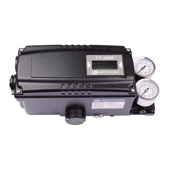
2. Product Description General YT-3300 series Smart Valve Positioner accurately controls valve stroke in response to an input signal of 4-20mA from the controller. Built-in micro-processor optimizes the positioner’s performance and provides unique functions such as Auto-Calibration, PID Control, Alarms, and HART Protocol Communications. -
Page 7: Product Number
Product Number ** YT-3300 series can be used for direct-mounting application. ** YT-3301 standard cable length is 5 meters. Maximum cable length is 20 meters. YT-3300/3301 series... -
Page 8: Product Specification
Product Specification Model YT-3300L YT-3300R YT-3301L YT-3301R Acting Type Single Double Single Double Single Double Single Double 4~20mA DC Input Signal 3.2mA(Standard), 3.8mA(Hart Included) Min. Current Signal 0.14~0.7 MPa (1.4~7 bar) Supply Pressure 10~150 mm 0~90° 10~150 mm 0~90° Stroke Max.450Ω... -
Page 9: Parts And Assembly - Yt-3300L & Yt-3300R
Parts and Assembly – YT-3300L & YT-3300R YT-3300L series exploded view YT-3300R series exploded view YT-3300/3301 series... -
Page 10: Parts And Assembly - Yt-3301L & Yt-3301R
Parts and Assembly – YT-3301L & YT-3301R Product Dimension 2.8.1 YT-3300L YT-3300/3301 series... -
Page 11: Yt-3300R
2.8.2 YT-3300R 2.8.2.1 YT-3300R standard 2.8.2.2 YT-3300R with L/S option YT-3300/3301 series... -
Page 12: Yt-3301L
2.8.3 YT-3301L 2.8.4 YT-3301R YT-3300/3301 series... -
Page 13: Installation
3. Installation Safety When installing a positioner, please ensure to read and follow safety instructions. Any input or supply pressures to valve, actuator, and / or to other related devices must be turned off. Use bypass valve or other supportive equipment to avoid entire system “shut down”. ... - Page 14 3. Attach the positioner with bracket to the actuator yoke – DO NOT TIGHTEN POSITIONER COMPLETELY. 4. Connect positioner’s feedback lever to the actuator clamp. The hole gap on the feedback lever is 6.5mm. The connection pin’s outer diameter should be less than 6.3mm.
-
Page 15: Yt-3300L Direct-Mounting Installation
9. After installing the positioner, operate the valve from 0% to 100% stroke by using direct air to the actuator (manual position). On both 0% and 100%, the feedback lever should not touch the lever stopper, which is located on the backside of the positioner. If the feedback lever touches the stopper, the positioner should be installed further away from the yoke. -
Page 16: Yt-3300R Installation
2. Mount YT-3300L onto actuator’s yoke by using 2 bolts. As you mount the positioner, please be careful not to lose o-rings from the air channel. Please ensure that the lever adapter connection has been properly installed onto actuator’s stem before tightly fastened. -
Page 17: Connections
Using hexagonal bolts and washer, fasten YT-3300R with the supplied bracket. Do not tighten bolts completely before correct mounting of YT-3300R has been confirmed. Insert YT-3300R’s main shaft into actuator’s stem, and place the bracket align to the actuator’s bolt holes. -
Page 18: Connection - Actuator
The length of pipeline system should not be extremely long. Longer pipeline system may affect flow rate due to the friction inside of the pipeline. Connection – Actuator 4.4.1 Single acting actuator – YT-3300 Singe acting type positioner is set to use OUT1 port. OUT1 port should be connected with supply pressure port from actuator when using single acting type of spring return actuator. -
Page 19: Double Acting Actuator - Yt-3301
4.4.4 Double acting actuator – YT-3301 Double acting linear (left) and rotary (right) type actuator Connection – Power 4.5.1 Safety When installing in hazardous and explosive gas area, conduit tube or pressure-proof packing union must be used. The compound charging box should be the flameproof type and must be sealed completely. -
Page 20: Terminal Overview
4.5.2 Terminal Overview Positioner Terminal IN +: Input Signal (+) IN -: Input Signal (-) Ground OUT+: Feedback Signal (+) OUT-: Feedback Signal (-) 4.5.2.1 Limit Switch Terminal – Mechanical Type <YT-3300> YT-3300/3301 series... -
Page 21: Limit Switch Terminal-Proximity Type
4. When using inside ground, use 3mm wrench to loosen locking bolts of the terminal box cover. 5. Adjustments Limit Switch Adjustment YT-3300 series can have limit switch option. If user wants to adjust the position, please loosen cam bolts and adjust cam. Mechanical Type Proximity Type... -
Page 22: Auto/Manual Switch (A/M Switch)
Auto/Manual Switch (A/M Switch) Auto/Manual Switch allows the positioner to be functioned as by-pass. If switch is set as Auto, the positioner will operate per input signal. If switch is set as Manual, the positioner will send supply pressure directly to the actuator. Variable Orifice Adjustment Positioner can cause hunting with extremely small size of the actuator. -
Page 23: Operation
6. Operation Safety Following process will operate valve and actuator. Before proceed with any AUTO Calibration, please separate valve from the entire system, so AUTO Calibration will affect entire valve process. Button Description Positioner has 4 buttons, and they enable to perform various functions. Fig. -
Page 24: Auto Calibration (Auto Cal)
6.3.1 Auto Calibration (AUTO CAL) Auto Calibration (AUTO CAL) automatically calibrates the positioner. “AUTO CAL” process takes about 2~3 minutes, and the duration of the process varies upon the size of the actuator. There are 3 types of AUTO CAL. Zero Point End Point KP, KI, KD... -
Page 25: Manual Mode (Manual)
6.3.2 Manual Mode (MANUAL) Manual mode is used to maneuver valve stem manually. During “MANUAL”, the positioner bypasses supply air to the actuator. The movement of the stroke does not affect the positioner’s save data valves. ⇨ ⇨ ⇨ <ENTER> <DOWN>... -
Page 26: P Value (Kp)
6.3.3.2 P value (KP) P value indicates the ratio of the compensation signal based on the percentage of error allowance. As the value increase, the positioner finds the target value quickly, but it is more likely to have hunting. ⇨ ⇨... -
Page 27: P_(Kp_), D_(Kd_), I_(Ki_) Values
6.3.3.5 P_ (KP_), D_ (Kd_) , I_(KI_) values P_, D_, and I_ values’ principles are same as P, D, and I values, but these values will be activated when the error percentage is within 1%. 6.3.4 Hand Calibration Mode (HAND CAL) The positioner can be manually calibrated by entering into Hand Calibration Mode. -
Page 28: End-Point Ratio For Valve (Pe_Trim)
⇨ ⇨ <ESC> <UP>/<DOWN) Match feedback <ENTER> signal with 20mA 6.3.4.3 End-Point Ratio for Valve (PE_TRIM) When reverse acting operating is used, End-Point can be adjusted within 10% of total valve stroke, without adjusting valve’s zero point. ⇨ ⇨ ⇨ <ENTER>... -
Page 29: Valve Mode (Valve)
⇨ ⇨ ⇨ <DOWN> <ENTER> <ESC> 3 times 6.3.5 Valve Mode (VALVE) 6.3.5.1 Acting Adjustment (ACT) The positioner can be set as Direct Action (DA) or Reverse Action (RA). ⇨ ⇨ ⇨ <ENTER> <DOWN> <ENTER> 6 seconds 3 times ⇨ ⇨... -
Page 30: User Characteristics (User Set)
6.3.5.3 User Characteristics (USER SET) In case positioner requires a specific characteristic, the valve characteristic curve can be made by selecting up to 16 points of the curve. ⇨ ⇨ ⇨ <ENTER> <DOWN> <ENTER> 6 seconds 2 times ⇨ ⇨ ⇨... -
Page 31: Split Range Mode (Split)
6.3.5.6 Split Range Mode (SPLIT) The valve can be operated by split range control – 4~12mA or 12~20mA. ⇨ ⇨ ⇨ <ENTER> <DOWN> <ENTER> 6 seconds 5 times ⇨ ⇨ <ESC> <UP>/<DOWN> 3 times <ENTER> 6.3.5.7 Custom Zero Setting Mode (CST ZERO) Custom Zero Setting Mode allows the user to set any specific point as zero position. -
Page 32: View Mode (View)
⇨ ⇨ ⇨ <ENTER> <DOWN> <ENTER> 8 times ⇨ ⇨ <ESC> <UP>/<DOWN> 3 times <ENTER> 6.3.6 View Mode (VIEW) Different information can be shown on the positioner’s LCD. <UP>/<DOWN> ⇨ ⇨ <ESC> <DOWN> <ENTER> 4 times Description Positioner model YT-3300L Main software version VERSION HART protocol version... -
Page 33: Error And Warning Code
7. Error and Warning Code Error code Error Code Code Description and Cause Action Positioner is improperly installed. Re-install the positioner. Positioner is not parallel to the Ensure the feedback lever does MT ERR L ground at 50% point. Lever is at not touch the lever stopper at 0% lower position than actual 50% point. - Page 34 Re-install the positioner. Ensure the feedback lever does not Pv is below 100. touch the lever stopper at 0% and The angle of feedback lever is too large. 100%. After re-installation, perform AUTO1 Re-install the positioner. ...
- Page 35 8. Main Software Map YT-3300/3301 series...
- Page 36 Manufacturer: Young Tech Co., Ltd #3022, Hagun-ri, Yangchon-myeon Kimpo-si, Kyeonggi-do, 415-843 South Korea Tel: +82-31-986-8545 Fax: +82-31-986-2683 Email: ytc@ytc.co.kr Copyright © Young Tech Co., Ltd. All Rights Reserved. YT-3300/3301 series...
Need help?
Do you have a question about the YT-3300 Series and is the answer not in the manual?
Questions and answers