Table of Contents
Advertisement
Advertisement
Table of Contents

Subscribe to Our Youtube Channel
Related Manuals for avolta PC40-AMK


Summary of Contents for avolta PC40-AMK
- Page 1 PC40-AMK USER MANUAL PORTABLE AIR-CONDITIONER...
-
Page 2: Very Important
VERY IMPORTANT Please read this instruction guide before install and using your portable air conditioner unit. This instruction manual is the universal-purpose version for the units that you purchase, it might be slightly different from the ones described in the manual, but it does not affect your proper operations and usage. - Page 3 9. This unit is for indoor cooling, heating and dehumidifying. 10. When turning on the unit, the fan will operate but the compressor will start up after the cooling alarm flashes for three minutes ● In heating function, the heating alarm will flash for 3.5 minutes before the compressor and fan start up.
- Page 4 ATTENTION For effective heating and cooling functions, please ensure that the following steps are undertaken: Extend the exhaust hose to a length of not more than 400 mm. The exhaust hose must be kept parallel and must not be bent up or down.
-
Page 5: Unpacking Instructions
instantly whenever you want. - Dehumidified and filtered air cycle improve breathing environments effectively. - Besides the remote control, your one touch electronic pad also provides easy-identifying manual operation. - 24 hour Programmable timer for cooling, heating and dehumidifying functions. - Unique sleep control function - 220~240 Volt 50Hz operation UNPACKING INSTRUCTIONS... -
Page 6: Name Of The Parts
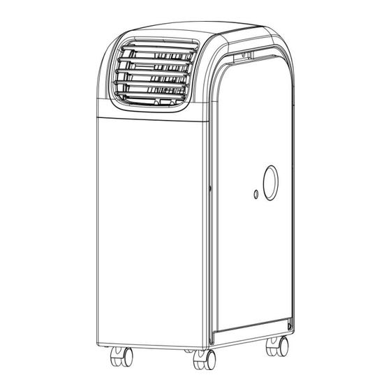
NAME OF THE PARTS 1. Control panel 2. Remote control receiver 3. Adjustable air vent 4. Joint tube 5. Exhaust hose 6. Upside drain hole 7. Cool air inlet 8. Cool air filter 9. Hot air inlet 10. Hot air filter 11. -
Page 7: Control Panel & Description Of Function
CONTROL PANEL & DESCRIPTION OF FUNCTION POWER KEY Press to turn unit "ON" or "OFF". FUNCTION Press this key to select cooling, heating, or dehumidifying. 3. TEMPERATURE REGULATION KEY (UP) During cooling function:This key raises the preset temperature by 1℃ each time it is pressed and the maximum limit is 30℃. -
Page 8: Programmable Timer
5. L.E.D. DISPLAY The display indicates the current setting temperature or the timer setting. When the set temperature or the timer is adjusted, the new setting is shown then the display returns the current set temperature. ※ The display is also used to show error codes should a fault occur, see ERROR CODES. - Page 9 3. Press the "POWER" key before the time out, the setting time will be canceled and the unit will turn off. 8. SLEEP CONTROL FUNCTION 1. While in cooling mode, press the SLEEP key to set the temperature. It increases1 ℃ after an hour and at most increases 2 ℃...
-
Page 10: Remote Control Function
REMOTE CONTROL FUNCTION 1. POWER On/Off switch Function “MODE” selector 2. FUNC 3. TIMER Hourly programming 4. AUTO Automatic fan speed 5. HI High fan speed 6. MID Medium fan speed 7. LOW Low fan speed 8. SLEEP Night operation selector 9. -
Page 11: Maintenance
NOTICE This unit can evaporate the condensation and distribute through the exhaust hose automatically. 1. When the unit is in the cooling function, it does not need the drain pipe installed. Please make sure that the rubber cap is locked on drain hole, when the unit is running. - Page 12 CONDENSER/EVAPORATOR Use a brush attachment with a vacuum cleaner. Casing Wipe with a damp cloth and polish with a soft cloth. To remove the air filter, please follows the arrow direction and pull the filter lightly, and then take out the filter for cleaning.
-
Page 13: Power Supply
POWER SUPPLY (1) Confirm the correct power. (2) Insert the plug into the outlet firmly In order to prevent any dangerous leakage. (3) Don’t pull power wire by force because it will cause damage to power wire. PLACE FOR USE Because the machine distributes hot air, please don’t place or operate in a narrow place. -
Page 14: Window Kit Install
EXHAUST HOSE INSTALL 1. Circumrotate the exhaust hose according to the direction as the arrowhead ① indicates and then the exhaust hose can be took out from the unit. 2. Circumrotate the exhaust hose according to the direction as the arrowhead ② indicates and then make it connect with the unit. -
Page 15: Troubleshooting
How to enjoy heating function? When operating heating function: Disassemble the outlet and the exhaust hose as arrow direction in Fig.01 and then exchange the two subassemblies to install. The finished illustration is as Fig.03. TROUBLE SHOOTING Problem Cause Trouble shooting Electrical short on both Contact an electrician for repair temperature sensor and PCB... -
Page 16: Specification
SPECIFICATION Model No. PC44-AMK Power Source 220-240V~50Hz Rated Power (EN60335) Cooling 1700W Heating 1500W Cooling Capacity 4400W Heating Capacity 4400W Moisture Removed 70liters/day Refrigerant R410A Dimensions (mm) 300Wx505Dx775H (CE) N 842/2006: R410A is a kind of fluorinated greenhouse gases covered by the Kyoto Protocol.
Need help?
Do you have a question about the PC40-AMK and is the answer not in the manual?
Questions and answers