
Related Manuals for avolta A007E-10C


Summary of Contents for avolta A007E-10C
- Page 1 Portable Air-conditioner User’s Manual(R290) For Model : A007E-10C Please read this user’s manual carefully to ensure proper use, maintenance and installation...
-
Page 2: Table Of Contents
Contents 1. Safety Awareness........................1 2. Name of Parts......................... 12 3. Accessories..........................12 4. Appearance and Function of Control Panel.................13 5. Appearance and Function of Remote Control..............14 6. Operation Introduction......................15 7. Installation Explanations...................... 17 8. Maintenance Explanations....................20 9. Troubleshooting........................20... -
Page 3: Safety Awareness
1. Safety Awareness 1. Safety Awareness VERY IMPORTANT! Please do not install or use your portable air conditioner before you have carefully read this manual. Please keep this instruction manual for an eventual product warranty and for future reference. Warning Do not use means to accelerate the defrosting process or to clean, other than those recommended by the manufacturer. - Page 4 The appliance must be placed in an area without any continuously sources of ignition (for example: open flames , gas or electrical appliances in operation). Do not puncture and do not burn. This appliance contains Y g (see rating label back of unit ) of R290 refrigerant gas. ...
- Page 5 7. When moving the air-conditioner, always turn off and disconnect the power supply, and move it slowly. 8. To avoid the possibility of fire disaster, the air-conditioner shall not be covered. 9. All the air-conditioner sockets must comply with the local electric safety requirements. If necessary, please check it for the requirements.
- Page 6 19. Keep ventilation openings clear of obstruction. 20. Any person who is involved with working on or breaking into a refrigerant circuit should hold a current valid certificate from an industry-accredited assessment authority, which authorizes their competence to handle refrigerants safely in accordance with an industry recognized assessment specification.
- Page 7 INSTRUCTIONS FOR REPAIRING APPLIANCES CONTAINING R290 1 GENERAL INSTRUCTIONS 1.1 Checks to the area Prior to beginning work on systems containing flammable refrigerants, safety checks are necessary to ensure that the risk of ignition is minimised. For repair to the refrigerating system, the following precautions shall be complied with prior to con-ducting work on the system.
- Page 8 accordance with the room size within which the refrigerant containing parts are installed; the ventilation machinery and outlets are operating adequately and are not obstructed; if an indirect refrigerating circuit is being used, the secondary circuit shall be checked for the presence of refrigerant;...
- Page 9 detection of refrigerant leaks. A halide torch (or any other detector using a naked flame) shall not be used. 6 LEAK DETECTION METHODS The following leak detection methods are deemed acceptable for systems containing flammable refrigerants. Electronic leak detectors shall be used to detect flammable refrigerants, but the sensitivity may not be adequate, or may need recalibration.
- Page 10 recovered safely. Prior to the task being carried out, an oil and refrigerant sample shall be taken in case analysis is required prior to re-use of reclaimed refrigerant. It is essential that electrical power is available before the task is commenced. a) Become familiar with the equipment and its operation.
- Page 11 an acceptable level to make certain that flammable refrigerant does not remain within the lubricant. The evacuation process shall be carried out prior to returning the compressor to the suppliers. Only electric heating to the compressor body shall be employed to accelerate this process.When oil is drained from a system,it shall be carried out safely.
- Page 12 • Check safety equipment before putting into service. c) Repair • Portable equipment shall be repaired outside or in a workshop specially equipped for servicing units with flammable refrigerants. • Ensure sufficient ventilation at the repair place. • Be aware that malfunction of the equipment may be caused by refrigerant loss and a refrigerant leak is possible.
- Page 13 • Evacuate again. • Cut out the compressor and drain the oil. Transportation, marking and storage for units that employ flammable refrigerants Transport of equipment containing flammable refrigerants Attention is drawn to the fact that additional transportation regulations may exist with respect to equipment containing flammable gas.
-
Page 14: Name Of Parts
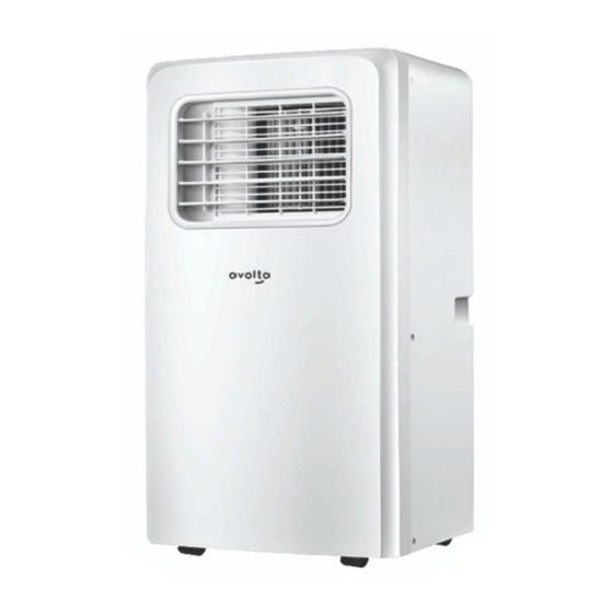
2. Name of Parts 2. Name of Parts Fig.1 Control panel Power cord Front panel Drainage outlet Louver Air inlet Castor Air outlet 3. Accessories 3. Accessories Part Description Quantity Exhaust hose Window Connector Housing adaptor Remote Controller... -
Page 15: Appearance And Function Of Control Panel
Window Kit 1 (optional) Dowel 2 (optional) Air outlet 1 (optional) Water pipe 1 (optional) Batteries 2 (optional) After unpacking, please check whether the above-mentioned accessories are included, and check their purposes in the installation introduction in this manual. 4. Appearance and Function of Control Panel 4. -
Page 16: Appearance And Function Of Remote Control
Power on/off Water full Temperature up High fan speed Temperature down Low fan speed Operation MODE Timer on/off Fan speed Cooling Timer on/off Dehumidifying Signal receiver Cooling & Heating model Power on/off Water full Temperature up High fan speed Temperature down Low fan speed Operation MODE Timer on/off... -
Page 17: Operation Introduction
Notes: - Do not drop the remote control. - Do not place the remote control in a location exposed to direct sunlight. 6. Operation Introduction 6. Operation Introduction Before starting operations in this section: 1) Find a place where there is power supply nearby. 2) As shown in Fig.2 and Fig.2a, install the exhaust hose, and adjust the window position well. - Page 18 Maximum heating Minimum heating DB/WB(℃) 27/--- 7/--- Check up whether the exhaust hose has been mounted properly. Cautions for cooling and dehumidifying operations: When using functions on cooling and dehumidifying, keep an interval of at least 3 minutes between each POWER. Power supply meets the requirements.
-
Page 19: Installation Explanations
Continuous Drainage When you plan to leave this unit unused for a long time, please remove the rubber blockage from the drainage hole at the bottom of unit, and drain all water outside. You can use the continuous drainage with a drainage hose connected to the bottom drain hole, when the unit working at the HEAT mode. - Page 20 Twist the housing adaptor and the window Connector to the ends of the exhaust hose. Insert the fixing clip of the housing adaptor into the openings at back of the air conditioner. Put the other end of the exhaust hose to the near windowsill (see Fig.4).
- Page 21 Water Full Alarm Function The inner water tray in the air-conditioner has one water level safety switches, it controls water level. When water level reaches an anticipated height, the water full indicator lamp lights up. (If water splash motor is damaged, when the water is full, please remove the rubber blockage at the bottom of unit, and all water will drain outside.) Fig.6...
-
Page 22: Maintenance Explanations
8. Maintenance Explanations 8. Maintenance Explanations Declaration: 1) Before cleaning, be sure to disconnect the unit from any electric supply outlet; 2) Do not use gasoline or other chemicals to clean the unit; 3) Do not wash the unit directly; 4) If the conditioner is damaged, please contact the dealer or repair shop. - Page 23 Troubles Possible Causes Suggested Remedies - Water full indicator lamp blinks, Dump the water out of the and water tray is full. water tray. - Room temperature is higher than 1.Unit does not start the setting temperature. (Electric Reset the temperature when pressing on/off heating mode) button...
Need help?
Do you have a question about the A007E-10C and is the answer not in the manual?
Questions and answers