
Related Manuals for Sleipner SE60S


Summary of Contents for Sleipner SE60S
- Page 1 Installation Guide For DC Electric Thruster Models SE60 DOCUMENT ID: SLEIPNER AS 5693 REVISION: P.O. Box 519 DATE: N-1612 Fredrikstad 2021 Norway LANGUAGE: www.sleipnergroup.com...
-
Page 2: Table Of Contents
Product Spare Parts and Additional Resources ....25 Warranty statement ............25 DECLARATION OF CONFORMITY MC_0020 Sleipner Motor AS P.O. Box 519, Arne Svendsensgt. 6-8 N-1612 Fredrikstad, Norway Declare that this product with accompanying standard control systems complies with the... -
Page 3: Bow Installation Considerations And Precautions
Before installation, it is important that the installer reads this guide to ensure necessary acquaintance with the product. The recommendations made in this manual are guidelines ONLY, and Sleipner Motor AS (Sleipner) strongly recommend that before installation, advice is obtained from a naval architect familiar with the particular vessel and regulations/ classifi cations. -
Page 4: Thruster Measurements
Propeller position will vary with each thruster model Single Propeller The gear leg/ propeller(s) must never extend out of the tunnel Tunnel centre line MG_0079 Thruster Measurements MC_0127 *60 s2 *60 s2 Measurement Measurement description code inch inch Internal tunnel diameter 7,28 7,28 Motor Height... -
Page 5: Thruster Specifications
- Flexible coupling between electro-motor and drive shaft protects electro motor and gear system if propeller jams. - Original Sleipner panels shut off automatically 6 minutes after last use. This interval can be adjusted in 5 min steps up to 60 minutes or turned off completely. -
Page 6: Positioning Of The Tunnel / Thruster
Pivot point important Lowered rotation power performance Stronger rotation power performance Water line Ø min 1/4 Ø (Recommended) min 1/4 Ø (Recommended) MG_0001 Positioning of the tunnel / thruster MC_0003 Aim to install the thruster as far forward as possible (1) Due to the leverage effect around the boats’... -
Page 7: Tunnel Length
Do not allow the variable length of the tunnel walls to vary in length excessively. EG. the top tunnel wall is x 4 longer than the bottom wall. Water flow must have space to "straighten" itself for best Cavitation performance. -
Page 8: Tunnel Installation In Sailboats
Pos. A Pos. B MG_0004 Tunnel installation in sailboats MC_0003 Some sail boats have a flat bottom and shallow draft in the bow section. This can make installing the thruster as far forward from the boats main pivot point diffi cult. -
Page 9: Water Deflection
High water force while underway High water force while underway from wave contact MG_0003 Water Deflection MC_0003 A possible problem in sail boats or fast powerboats is that a non-rounded surface can generate drag from the back face of the tunnel, as it creates “flat”... -
Page 10: Tunnel Ends
R = 0,1 x D (10%) Cavitation Angled tunnel ends for steel/ aluminium hulls MG_0002 Tunnel Ends MC_0003 Rounded tunnel ends will maximise thrust and minimise noise and cavitation. For best performance round the tunnel connection to the hull-side as much as possible. The minimum rounding has a radius of 10% of the diameter of the tunnel. -
Page 11: Tunnel Installation
8 x layers of fiberglass and resin 8 x layers of fiberglass and resin MG_0005 Tunnel Installation MC_0003 IMPORTANT We recommend that a professional does the fi breglass, steel or aluminium fi tting of the tunnel. These instructions are only general instructions and do not explain in any way the details of fi... - Page 12 Hull Hull Layers of Layers of fiberglass fiberglass and resin and resin Tunnel Additional Layers of Hull fiberglass and resin Welding Tunnel *Fiberglass *Steel/ Hull Aluminium Hull Hull R = D x 0,1 Layers of fiberglass R = D x 0,1 and resin Tunnel Additional Layers of...
-
Page 13: Stern Tunnel Installation
Stern Tunnel Installation MC_0003 Stern thruster installation has extra considerations and precautions and thruster installation procedures. See the attached manual supplied in the stern thruster kit Stern Thruster Installation Guide SE60/185 s2 5693 2021... -
Page 14: Thruster Installation Considerations And Precautions
Before installation, it is important that the installer reads this guide to ensure necessary acquaintance with the product. The recommendations made in this manual are guidelines ONLY, and Sleipner Motor AS (Sleipner) strongly recommend that before installation, advice is obtained from a naval architect familiar with the particular vessel and regulations/ classifi cations. -
Page 15: Gear Leg & Motor Bracket Installation
Boats 2 - 4 centre line *P*IP Measurement ØC Boats *P*IP Description centre line inch Tunnel ØA 1.18 centre line 0.91 Tunnel ØC 0.35 centre line *P- Propositional ØA *IP- Ignition Protected Place top motor bracket and bolt plate Measure the drive shaft has come Stern through the motor... -
Page 16: Propeller Installation
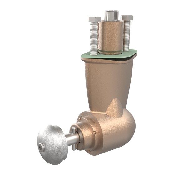
Drive pin Propeller Washer Lock nut Anode Anti-fouling Anode holding screw Apply Loctite 243 or similar MG_0028 Propeller Installation MC_0018 ! Please refer to the graphic for special considerations relating to your model ! Centre the drive pin and Insert the propeller onto the shaft spine. Rotate the propeller until the drive pin aligns with the internal slot in the propeller. -
Page 17: Motor Installation
Coupling Turn gear leg shaft so the motor coupling fits into the slots. Drive Pin Gasket > 30° Motor FASTEN (18 Nm) (13.28 lb/ft) Motor support IMPORTANT Do not position support on the motor cap. MG_0029 Motor Installation MC_0043 ! Please refer to the graphic for special considerations relating to your model ! Insert the drive pin to the motor drive shaft. -
Page 18: Thruster Electrical Installation
Fuse Main switch Battery Thruster 12V or Motor Multi-lug configuration Ensure lug faces are back to back. IMPORTANT Do NOT use washers between lugs, this causes overheating and fire. Spring washers must be placed in the outer position before tightening the nut. Lugs (M8) Nut Tighten to *max... -
Page 19: Electrical Specifications
Electrical Specifi cations MC_0044 SE60/185 s2 5693 2021... -
Page 20: Control Panel Cable Installation
(NB: If two or more control panels are operated at the same time in opposite directions, the electronic control box will stop the thruster until it receives a single signal or thrust in one direction.) • Sleipner on/off equipment it is entirely “plug & play” and require no additional confi guration setup. See the Control panel manual for more information. SE60/185 s2... -
Page 21: Visual Wiring Diagram
Visual Wiring Diagram With Automatic Main Switch: 6 1278-xxM 5-LEAD CONTROL CABLE 6 1278-xxM 5-LEAD CONTROL CABLE STERN 6 1265 5-LEAD Y-CONNECTOR 6 1265 5-LEAD Y-CONNECTOR STERN 5A fuse 5A fuse STERN Switch Switch 6 1278-xxM 5-LEAD 6 1278-xxM 5-LEAD CONTROL CABLE CONTROL CABLE 6 1277-xxM 4-LEAD... -
Page 22: Technical Wiring Diagram
Technical Wiring Diagram MG_0032 SE60/185 s2 5693 2021... -
Page 23: Control Panel Installation
Example of control panels (4) COVERING CAPS GASKET CABLES (4) SCREWS (4) COVERING CAPS COVERING CAP GASKET CABLES (4) SCREWS GASKET CABLES (4) SCREWS MG_0026 Control Panel Installation MC_0042 ! Please refer to the graphic for special considerations relating to your model ! Find a suitable location for the control panel where it does not obstruct or is obstructed by other devices. -
Page 24: Pre-Delivery Checklist
Pre-delivery Checklist MC_0033 ..The bolts holding the gear house and motor bracket together are tightened correctly... The bolts holding the motor to its bracket are tightened correctly... All electrical connections are clean, dry and tight, and the correct cable, fuse and main switch size. -
Page 25: Service And Support
10. This warranty gives you specific legal rights, and you may also have other rights which vary from country to country. Patents MC_0024 At Sleipner we continually reinvest to develop and offer the latest technology in marine advancements. To see the many unique designs we have patented visit our website www.sleipnergroup.com/patents SE60/185 s2... - Page 26 Notes MC_0037 ..............................................................................................................................................................................................................................................................................................................................................................................................................................................................................................................................................................................................................................................................................................................................................................................................................................................................................................................................................................................................................................................................................................................................................................................................................................................................................................................................................................................................................................................................................................................................................................................................................SE60/185 s2 5693 2021...
- Page 27 Notes MC_0037 ..............................................................................................................................................................................................................................................................................................................................................................................................................................................................................................................................................................................................................................................................................................................................................................................................................................................................................................................................................................................................................................................................................................................................................................................................................................................................................................................................................................................................................................................................................................................................................................................................................SE60/185 s2 5693 2021...
- Page 28 © Copyright Sleipner Motor AS, 2021 The information given in the document was correct at the time it was published. However, Sleipner Motor AS can not accept liability for any inaccuracies or omissions it may contain. Continuous product improvement may change the product specifi cations without notice.
Need help?
Do you have a question about the SE60S and is the answer not in the manual?
Questions and answers