Endress+Hauser Liquiphant FTL64 Operating Instructions Manual
Point level switch for liquids in high-temperature applications
Hide thumbs
Also See for Liquiphant FTL64:
- Operating instructions manual (64 pages) ,
- Technical information (52 pages) ,
- Brief operating instructions (41 pages)
Table of Contents
Advertisement
Quick Links
KA01480F/00/EN/01.20
71498555
2020-11-30
Products
Brief Operating Instructions
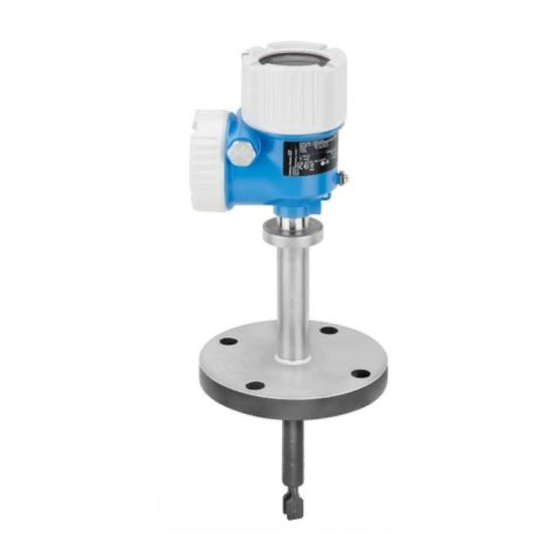
Liquiphant FTL64
Vibronic
Point level switch for liquids in high-temperature
applications
These Instructions are Brief Operating Instructions; they are
not a substitute for the Operating Instructions pertaining to
the device.
Detailed information about the device can be found in the
Operating Instructions and the other documentation:
Available for all device versions via:
• Internet:
www.endress.com/deviceviewer
• Smart phone/tablet: Endress+Hauser Operations App
Solutions
Services
Advertisement
Table of Contents

Related Manuals for Endress+Hauser Liquiphant FTL64


Summary of Contents for Endress+Hauser Liquiphant FTL64
- Page 1 Operating Instructions pertaining to the device. Detailed information about the device can be found in the Operating Instructions and the other documentation: Available for all device versions via: • Internet: www.endress.com/deviceviewer • Smart phone/tablet: Endress+Hauser Operations App...
- Page 2 Liquiphant FTL64 Order code: XXXXX-XXXXXX Ser. no.: XXXXXXXXXXXX Ext. ord. cd.: XXX.XXXX.XX Serial number www.endress.com/deviceviewer Endress+Hauser Operations App A0023555 Endress+Hauser...
-
Page 3: Table Of Contents
Liquiphant FTL64 Table of contents Table of contents About this document ............. . 3 Symbols . -
Page 4: Basic Safety Instructions
Basic safety instructions Liquiphant FTL64 This symbol alerts you to a dangerous situation. Failure to avoid this situation can result in serious or fatal injury. CAUTION This symbol alerts you to a dangerous situation. Failure to avoid this situation can result in minor or medium injury. -
Page 5: Designated Use
Modifications to the device Unauthorized modifications to the device are not permitted and can lead to unforeseeable dangers. ‣ If, despite this, modifications are required, consult with Endress+Hauser. Repair To ensure continued operational safety and reliability: ‣ Only perform repair work on the device if this is expressly permitted. -
Page 6: Product Safety
• Enter the serial number on the nameplate into the Endress+Hauser Operations App or use the Endress+Hauser Operations App to scan the 2-D matrix code (QR Code) on the... -
Page 7: Storage And Transport
Liquiphant FTL64 Incoming acceptance and product identification 3.2.1 Nameplate Order code: Ser. no.: Ext. ord. cd.: Pmax: 0.83 W PNP Dev.Rev.: A0038187 1 Nameplate specifications Trademark (Endress+Hauser) Trade name (Device name) Manufacturer' s address (Certificate holder) Production location (Assembly plant) -
Page 8: Installation
Installation Liquiphant FTL64 A0042422 2 Handling the device Installation WARNING Loss of protection rating if the device is opened in a wet environment. ‣ Only open the device in a dry environment! • Any orientation for device with short pipe up to approx. 500 mm (19.7 in) •... -
Page 9: Installation Conditions
Liquiphant FTL64 Installation A0042329 3 Installation examples in a vessel, pipe or tank Temperature spacer with gas-tight welded glass feedthrough for tank with insulation and/or high process temperatures Installation conditions 4.1.1 Pay attention to temperature Difference in temperature between outer and inner side of flange must not exceed 60 °C (140 °F). - Page 10 Installation Liquiphant FTL64 A0042298 4 Difference in temperature between outer and inner side of flange Insulation Temperature of flange, outer side Temperature of flange, inner side, for PFA (conductive) maximum 230 °C (446 °F) Difference in temperature for PFA (conductive) maximum 60 °C (140 °F) 4.1.2...
- Page 11 Liquiphant FTL64 Installation 4.1.3 Take viscosity into consideration Low viscosity Low viscosity, e. g. water: < 2 000 mPa⋅s It is permitted to position the tuning fork within the installation socket. > 25 (0.98) A0042333 6 Installation example for low-viscosity liquids. Unit of measurement mm (in) Diameter of installation socket: at least 50 mm (2.0 in)
- Page 12 Installation Liquiphant FTL64 4.1.4 Avoid buildup • Use short installation sockets to ensure that the turning fork can project freely into the vessel. • Install preferably flush mount on vessels or in pipes. • Leave sufficient distance between the buildup expected on the tank wall and the tuning fork.
- Page 13 Liquiphant FTL64 Installation A0042340 9 Take clearance into consideration 4.1.6 Support the device NOTICE If the device is supported incorrectly, shocks and vibrations can damage the coated surface. ‣ Only use suitable supports. Support the device in the event of severe dynamic load. Maximum lateral loading capacity of the pipe extensions and sensors: 75 Nm (55 lbf ft).
-
Page 14: Mounting The Measuring Device
Installation Liquiphant FTL64 A0042356 10 Examples of support in the event of dynamic load Mounting the measuring device 4.2.1 Required tool • Open-ended wrench for sensor installation • Screwdriver for electrical connection 4.2.2 Installation Align the tuning fork with the marking Use the marking to align the tuning fork in such a way that medium can run off easily and deposit buildup is avoided. - Page 15 Liquiphant FTL64 Installation 316L/G1 A0042348 11 Marking to align the tuning fork Installing in pipes • Flow velocities up to 5 m/s at a viscosity of 1 mm /s(cSt) and density 1 g/cm (SGU) Check for correct functioning in the event of other process medium conditions •...
-
Page 16: Sliding Sleeves
Installation Liquiphant FTL64 A0042423 13 Screwing in the device Aligning the cable entry 4 0.7 Nm A0042355 14 Housing with external locking screw The locking screw is not tightened when the device is delivered. Loosen the external locking screw (maximum 1.5 turns). -
Page 17: Electrical Connection
Liquiphant FTL64 Electrical connection Does the measuring device conform to the measuring point specifications? For example: • Process temperature • Process pressure • Ambient temperature range • Measuring range Are the measuring point number and labeling correct (visual inspection)? Is the measuring device adequately protected against precipitation and direct sunlight? -
Page 18: Connecting The Measuring Device
Electrical connection Liquiphant FTL64 5.1.2 Connecting protective earth (PE) The protective earth conductor at the device must only be connected if the device' s operating voltage is ≥ 35 V or ≥ 16 V eff. When the device is used in hazardous areas, it must always be included in the potential equalization of the system, irrespective of the operating voltage. - Page 19 Liquiphant FTL64 Electrical connection Behavior of output signal • OK status: load on (switched through) • Demand mode: load off (blocked) • Alarm: load off (blocked) Terminal assignment Always connect an external load. The electronic insert has integrated short-circuit protection.
- Page 20 Electrical connection Liquiphant FTL64 Behavior of switch output and signaling ΔU <3.8 mA ΔU <3.8 mA <3.8 mA A0031901 17 Behavior of switch output and signaling, electronic insert FEL61 MAX DIP switch for setting MAX safety mode MIN DIP switch for setting MIN safety mode...
- Page 21 Liquiphant FTL64 Electrical connection Selection tool for relays 207 230 253 A0042052 18 Recommended minimum holding power/rated power for load Holding power/rated power in [VA] Operating voltage in [V] AC mode • Operating voltage: 24 V, 50 Hz/60 Hz •...
- Page 22 Electrical connection Liquiphant FTL64 Supply voltage WARNING Failure to use the prescribed power unit. Risk of potentially life-threatening electric shock! ‣ The FEL62 may only be powered by devices with safe galvanic isolation, as per IEC 61010-1. U = 10 to 55 V Observe the following as per IEC/EN61010-1: Provide a suitable circuit breaker for the device, and limit the current to 500 mA, e. g.
- Page 23 Liquiphant FTL64 Electrical connection Terminal assignment U = 10...55 V DC 350 mA I max: 350 mA 55 V >0,7 >0,5 0.5 A L+ L- A0036061 19 3-wire DC-PNP, electronic insert FEL62 Connection wiring with terminals Connection wiring with M12 plug in housing as per EN61131-2 standard...
- Page 24 Electrical connection Liquiphant FTL64 Behavior of switch output and signaling (L–) ΔU <100 µA (L–) (L–) ΔU <100 µA (L–) <100 µA (L–) A0033508 20 Behavior of switch output and signaling, electronic insert FEL62 MAX DIP switch for setting MAX safety mode...
- Page 25 Liquiphant FTL64 Electrical connection Supply voltage U = 19 to 253 V , 50 Hz/60 Hz/19 to 55 V Observe the following as per IEC/EN61010-1: Provide a suitable circuit breaker for the device, and limit the current to 500 mA, e. g. by installing a 0.5 A fuse (slow-blow) in the phase (not the neutral conductor) of the supply circuit.
- Page 26 Electrical connection Liquiphant FTL64 Terminal assignment >0,7 U = 19...55 V DC >0,5 U 19...253 V AC 0.5 A A0036062 21 Universal current connection with relay output, electronic insert FEL64 When bridged, the relay output works with NPN logic...
- Page 27 Liquiphant FTL64 Electrical connection Behavior of switch output and signaling A0033513 22 Behavior of switch output and signaling, electronic insert FEL64 MAX DIP switch for setting MAX safety mode MIN DIP switch for setting MIN safety mode LED red for alarm...
- Page 28 Electrical connection Liquiphant FTL64 Connectable load Loads switched via 2 potential-free changeover contacts (DPDT) • I ≤ 6 A (Ex de 4 A), U~ ≤ AC 253 V; P~ ≤ 1 500 VA, cos φ = 1, P~ ≤ 750 VA, cos φ > 0.7 • I ≤ 6 A (Ex de 4 A) to DC 30 V, I DC ≤...
- Page 29 Liquiphant FTL64 Electrical connection Terminal assignment >0,7 >0,5 U = 9...20 V DC 0.5 A L- PE A0037685 23 DC connection with relay output, electronic insert FEL64 DC When bridged, the relay output works with NPN logic Connectable load Endress+Hauser...
- Page 30 Electrical connection Liquiphant FTL64 Behavior of switch output and signaling A0033513 24 Behavior of switch output and signaling, electronic insert FEL64 DC MAX DIP switch for setting MAX safety mode MIN DIP switch for setting MIN safety mode LED red for alarm...
- Page 31 Liquiphant FTL64 Electrical connection Power consumption P ≤ 150 mW with Nivotester FTL325P or FTL375P Behavior of output signal • OK status: MAX operating mode 150 Hz, MIN operating mode 50 Hz • Demand mode: MAX operating mode 50 Hz, MIN operating mode 150 Hz •...
- Page 32 Electrical connection Liquiphant FTL64 Connection cable • Maximum cable resistance: 25 Ω per core • Maximum cable capacitance: < 100 nF • Maximum cable length: 1 000 m (3 281 ft) Behavior of switch output and signaling 150 Hz 50 Hz...
- Page 33 2-wire NAMUR > 2.2 mA/ < 1.0 mA (electronic insert FEL68) • For connection to the isolating switch repeater as per NAMUR (IEC 60947-5-6), e. g. Nivotester FTL325N from Endress+Hauser • Signal transmission H-L edge 2.2 to 3.8 mA/0.4 to 1.0 mA as per IEC 60947-5-6 (NAMUR) on two-wire cabling •...
- Page 34 Electrical connection Liquiphant FTL64 Terminal assignment IEC 60947-5-6 8,2 V DC NAMUR – >0,7 >0,5 L- L+ A0036066 27 2-wire NAMUR ≥ 2.2 mA/≤ 1.0 mA, electronic insert FEL68 Endress+Hauser...
- Page 35 Liquiphant FTL64 Electrical connection Behavior of switch output and signaling 2.2...3.8 mA 0.4...1.0 mA 2.2...3.8 mA 0.4...1.0 mA < 1.0 mA A0037694 28 Behavior of switch output and signaling, electronic insert FEL68 MAX DIP switch for setting MAX safety mode...
-
Page 36: Post-Connection Check
Electrical connection Liquiphant FTL64 5.2.9 Connecting the cables Required tool • Flat-blade screwdriver (0.6 mm x 3.5 mm) for terminals • Torque wrench A0018023 29 Example of coupling with cable entry, electronic insert with terminals M20 coupling (with cable entry), example Maximum conductor cross-section 2.5 mm... -
Page 37: Operation Options
Liquiphant FTL64 Operation options Are all the housing covers installed and tightened? Optional: Is the cover tightened with securing screw? Operation options Operating concept • Operation with button and DIP switches on the electronic insert • Display with optional Bluetooth module and SmartBlue (app) via Bluetooth® wireless technology •... -
Page 38: Functional Test Using The Button On The Electronic Insert
Operation options Liquiphant FTL64 Functional test using the button on the electronic insert The functional test must be performed when the device is in the OK state. OK state: MAX safety and sensor free or MIN safety and sensor covered. -
Page 39: Heartbeat Diagnosis And Verification With Bluetooth® Wireless Technology
Liquiphant FTL64 Commissioning A0033419 32 Functional test with test magnet Heartbeat diagnosis and verification with Bluetooth® wireless technology 6.5.1 Access via Bluetooth® wireless technology A0033411 33 Remote operation via Bluetooth® wireless technology Smartphone or tablet with SmartBlue (app) -
Page 40: Switching On The Measuring Device
Commissioning Liquiphant FTL64 Switching on the measuring device During the power-up time, the device output is in the safety-oriented state, or in the alarm state if available: • For electronic insert FEL61, the output will be in the correct state for a maximum of 4 s after powering up the device. - Page 44 *71498555* 71498555 www.addresses.endress.com...