Advertisement
Quick Links
Advertisement

Related Manuals for Canine Innovations Invisible Fence ICT 801

Summary of Contents for Canine Innovations Invisible Fence ICT 801
- Page 1 Top Dog Kit ICT Transmitter and Installation Manual...
- Page 2 Dear Canine Company Client, Congratulations! The Top Dog Invisible Fence Brand Kit you have purchased is from the ® finest brand in traditional electronic pet containment system available today. It will provide your pet years of reliable protection. We have included instructions to help you install your system and train your pet. Please review each of them carefully before you begin.
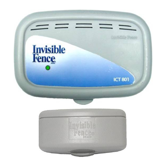
- Page 3 Tools & Equipment Here is the list of items included with your Top Dog Kit: (1)- ICT 801 Invisible Fence Brand (2)- Bundle of 50 Flags ® Transmitter (1)- Driveway Sealer (1)- Classic Computer Collar unit & (1)- Post Tightening Tool ®...
- Page 4 Planning your Invisible Fence Brand System: ® Most of the Invisible Fence Brand installations will be straight forward, but every client’s ® property is unique. Following the steps outlined, knowing your equipment, how to work around obstacles, and deal with special situations should ensure a successful system installation and prevent unnecessary service calls.
- Page 5 the fence you leave 3 to 5 ft. of space between where you will want your pet to run safely, and where the Computer Collar unit will begin to tone. ® 4. At your Asphalt/Concrete/Gravel driveway, select where you will cross the driveway with the perimeter (boundary) wire.
-
Page 6: Installation Diagrams
Installation Diagrams “Banana” Loop Installation Basic Loop Double loop around one side of the house. One loop around the perimeter of the Only selected house exits are protected. property. All house exits are protected. “Hourglass” Installation Basic Perimeter Loop with Inner Loops One loop around the perimeter of the One loop around the perimeter of the property with loops pinched in on sides. - Page 7 A typical Invisible Fence Brand installation ® Perimeter (Boundary) Wire surrounds the entire property. Invisible Fence Brand systems only ® work when all of the signal field wire, Pre-Twisted (neutral) wire (including the loop (boundary) wire and the pre-twisted pair), forms one continuous closed circuit.
- Page 8 Color Code Chart for Marking Utilities: Electric Gas – Oil Communications Water Sewer Running Twisted Pair (neutral) wire Twisted pair is two lengths of the same signal field loop wire, one carrying the signal out from the transmitter; the other carrying it back to the transmitter. You can identify these as the brownish/red wire and a black wire ‘twisted’...
- Page 9 Where twisted wire exits home (Inside the home) 2. Push the twisted pair out the exit hole until it exits that outside of the house. To protect the twisted pair on the OUTSIDE of your home, you may run the twisted pair through a length of PVC conduit (we suggest using a 1/2”...
- Page 10 The perimeter (boundary) wire does not have to be buried to work, but should be buried to protect the wire from the elements and other entities that may cause the wire to break. 1. Dig the trench for your perimeter (boundary) wire using the spade or gas powered edger and push your perimeter (boundary) wire in the trench as you move around your yard - beginning where your twisted pair ended.
- Page 11 a. Concrete and Asphalt driveways - Make a straight line using a chalk line to make the cut easier to follow. Using a mason blade, run the circular saw or gas powered cut-off saw, along the line making sure to clean out the debris and dust from the newly cut joint.
- Page 12 d. Continue to bury your perimeter (boundary) wire around your property until you reach the twisted pair where you started. The below section will describe how to connect the wires together in compliance with Invisible Fence Brand Standards. ® Connecting your Invisible Fence Brand wires ®...
- Page 13 3. Tightly twist the ends of the wires together so that they will maintain good contact with each other. Hold the two wires parallel to each other and tie an overhand knot (there should be about 3 inches of space between the knot and the spliced wires. Place a wire nut over the spliced wires and twist until the wire nut does not spin.
- Page 14 LP 4200 Surge Protector Why install an LP 4200 Lightning strikes within 1-2 miles of your installation can create power surges or spikes, which may damage your unprotected Invisible Fence Brand pet containment system. ® The Surge Protector is designed to protect your Invisible Fence Brand pet containment ®...
- Page 15 Step 2: We recommend that, if possible, may also interfere with the operation of use the outlet center screw that holds the the fence transmitter. cover plate in place to secure the Surge Protector to the outlet. To do this, tape the top of the cover plate to the wall, and then remove the cover plate center screw.
- Page 16 Step 4: Determine the length of wire needed to pass from the Surge Protector to the ICT Fence Transmitter. Measure and cut the length of twisted pair wires, then strip approximately 3/8-inch of insulation at both ends. Step 5: Insert the ends of the transmitter wires into the right 2 black connectors at the bottom of the Surge Protector labeled “Transmitter”.
- Page 17 ICT 801 or 802 Transmitter 2. As described in the LP 4200 Step 6 (and shown below), insert the opposite stripped ends of the two transmitter wires into the terminals for the appropriate loop on the ICT Transmitter. Push in the plastic tabs and insert the wires, one into each port. Let go of the tabs once the wires have been pushed up in the port and the wires will be secure into the appropriate Loop terminal.
- Page 18 ICT 801 Transmitter Installations: Setup and Operational Features/Functions of Transmitters ICT 801 Transmitter Installations: The ICT 801 is a single loop programmable transmitter designed for installations with up to 3,000 feet of signal field wire and up to 150 feet of twisted pair wire. The ICT 801 has one signal field adjustment to increase or decrease the width of the signal field.
- Page 19 Loop 1: Loop 1 is always functioning on the ICT 801. (No indicator light on the circuit board.) L1 Freq.: Select either 7K or 10K signal for Loop 1. The default setting is 7K. L1 Signal: Select either Indoor or Outdoor mode for Loop 1. The default setting is Indoor. Saturation: When lit, indicates Loop 1 transmitter output saturation.
- Page 20 a. For ICT 801: The L1 Freq. LED begins to blink. b. For ICT 802: The Loop 1 LED begins to blink. 2. Release the S1 button. 3. Momentarily press and release the S2 button to toggle between each setting option. 4.
- Page 21 There is one signal field adjustment knob on the ICT 801 transmitter and two signal field adjustment knobs on the ICT 802 transmitter. Turning the signal field adjustment knob clockwise increases the signal field width. Conversely, turning it counter-clockwise decreases the signal field width. IMPORTANT: These adjustments do not change the correction level of the Invisible Fence Brand Computer Collar...
- Page 22 *ONLY use the post tightening tool to tighten the correction posts. Use of other tools will void the warranty. DO NOT secure the correction posts in the Computer Collar unit with ® any kind of glue or adhesive. Post Cover Correction Posts Retaining Strip/Backing Plate Nylon Strap...
- Page 23 1. Position the collar strap unit high on the pet’s neck with the Computer Collar unit ® under its lower jaw. 2. To avoid having a collar that is too tight on a thick-haired pet; thin some hair away to make skin contact with the correction posts.
- Page 24 • GREEN = Power Cap unit is good. ® • RED = The Power Cap unit is dead. Replace immediately. Do not rely on the Invisible ® Fence Brand pet containment system to contain the pet until the Power Cap unit is ®...
- Page 25 Turn and line up with the marks to Lock On average, the Power Cap unit should be changed every 3 months. Low temperatures, ® the number of times the pet challenges the system boundary, and improper collar fit can all reduce Power Cap unit life.
-
Page 26: Troubleshooting
Troubleshooting Symptom Possible Cause Action Pet is getting out. • Power Cap ® ® Battery in the Computer • Replace the Power Cap Battery. • Properly fit the collar. ® Unit is dead or weak. Collar ® • Contact your Invisible Fence Brand Dealer. - Page 27 Warning 2: The control panel component of the system includes visual and audible signals to warn of a system malfunction. The control panel should be installed where such signals may be easily seen and heard. If the control panel is installed in an enclosed box, or in a place not readily accessible to the customer, the customer will not benefit from the system’s warning functions, for which Invisible Fence Brand, Inc., as well as Invisible Fence...
Need help?
Do you have a question about the Invisible Fence ICT 801 and is the answer not in the manual?
Questions and answers