
Related Manuals for Bartlett 700 Series


Summary of Contents for Bartlett 700 Series
- Page 1 Operation Manual Model V6-CF Series 700 Controller 1404 Avenue M Fort Madison, IA 52627 319-372-8366 www.bartinst.com...
-
Page 2: Table Of Contents
Table of Contents INTRODUCTION ............................2 PRECAUTIONS ............................2 CONTROLLER FRONT PANEL ......................3 QUICK START ............................4 FIRST FIRING OF THE KILN .........................5 ........................5 ROGRAM THE CONTROLLER ..................6 EVIEW THE SAMPLE PROGRAM BEFORE FIRING ............................7 TART THE IRING ..........................7 EVIEW THE ESULTS CONE FIRE PROGRAMMING........................8 VARY-FIRE..............................9... -
Page 3: Introduction
Introduction This manual covers the operation of the V6-CF series 700 kiln controller. The V6-CF is a versatile controller that regulates the temperature in your kiln so you can fire a variety of products like ceramics, glass, or jewelry. The experienced operator can go straight to the quick start guide. The novice can learn more about different types of firing by reading the programming sections of the manual and the ceramics and glass introductions on our web site www.bartinst.com... -
Page 4: Controller Front Panel
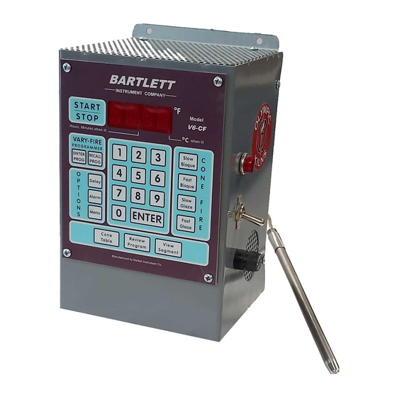
Controller Front Panel START-STOP LED DISPLAY p. 11 Decimal in lower right indicates temperature in Decim al in middle indicates a time. VARY-FIRE NUMBER KEYS ENTER PROG p. 9 for entering RECALL PROG p. 11 temperatures and times. Hot Keys p. 16 CONE FIRE p. -
Page 5: Quick Start
QUICK START Read all precautions before using your controller. Apply power to the kiln/controller Clear the display and get to the idle mode by pressing ENTER. Program the controller. Review the program before firing to ensure the correct program is ready to fire. Press Start. -
Page 6: First Firing Of The Kiln
First Firing of the Kiln The purpose of the first firing is to put a protective oxide layer on the elements and thermocouple. The first firing is done without ware in the kiln that might give off fumes that contaminate the elements. This first firing should have shelves and witness cones. -
Page 7: Review The Sample Program Before Firing
Review the sample program before firing. Press Review Program key, the display will cycle through the following information. Display shows Description F-GL Firing speed, fast glaze PRHT/0.00 Shows zero preheat time CONE/ 04 Programmed for cone 04 °F /1945 Top temperature for cone 04 CNOS/0 Shows 0°F cone adjustment Indicates zero hold at the top... -
Page 8: Start The Firing
Start the Firing. Press start to begin the firing The display will show –ON- then the current temperature. You will hear clicking when the relays cycle power to the elements to regulate the temperature. This firing will take around 6 to 7 hours. End of firing At the end of the firing, the display will flash between CPLT... -
Page 9: Cone Fire Programming
CONE FIRE Programming This is the quickest and easiest method to program the controller to fire ceramics. Programming consists of choosing the firing speed and entering the clay or glaze’s cone number. The firing speed is chosen by the type of firing and thickness of the clay. The bisque firings include water smoking and carbon burn-out stages. -
Page 10: Vary-Fire
VARY-FIRE The V6-CF has 6 vary-fire user programs to store and reuse. Each program has from 1 to 8 segments (2 to 16 segments if 16-S option is on). Each segment has a firing rate, a soak temperature, and a hold time. Each Each Segment has: program... -
Page 11: Calculating Ramp Rates For Vary Fire
NOTES: For Vary-Fire programming The first ramp rate of any user program must be an increasing ramp which means the segment temperature must be greater than the starting kiln temperature. To ramp up or down at the maximum rate, enter a rate of 9999. To program a down ramp, you enter the rate/hour then a temperature below the previous segment’s temperature. -
Page 12: Write Your Own Cone Fire Program
RECALL PROGRAM is used to recall a previously programmed firing profile. Example: To recall user program #5, use the following: Step Press Display Comment RECALL Alternately flashing: The controller is ready to accept the desired user number. PROG USEr & 1 Indicates the user program selected. -
Page 13: Operation Of The Controller During A Firing
Operation of the Controller during a firing The V6-CF controller eliminates much of the “babysitting” that is required with a manual kiln. To ensure the most consistent results from one firing to the next, you should understand how the controller operates and monitor the firing to ensure proper operation. - Page 14 Step 1 Read temperature inside kiln Step 2 Compare temperature traveling set point Controller Flow Chart If temperature is above If temperature is below set point, set point turn relay off turn relay on Return to the top repeat the process The block diagram and flow chart show that the kiln control system, in its simplest form, works like your thermostat at home –...
-
Page 15: End Of Firing - Cplt
END OF FIRING - CPLT At the end of the firing, the display will flash between End of firing CPLT / Firing time / kiln temperature Press ENTER to return to IdLE The display will now flash IdLE / kiln temperature. You may open the kiln when the temperature has cooled to 150°F. -
Page 16: View (Information) Section
VIEW (information) SECTION View Section - Contains buttons to look up cone temperatures, review programs, and view the current segment. View Segment is also used to skip step during Vary-Fire Programs. Cone Table Used to look up the temperature of various cone numbers. The temperature that is displayed is for self-supporting cones with a heating rate of 108oF/hr. -
Page 17: View Segment
In Vary Fire Mode - The display will show in the following order: the user program # (USEr) the number of segments (SEG) 1st ramp rate (rA 1) 1st segment temperature ( F 1) 1st hold time (HLd1) (If there is more than 1 segment, then the ramp rate, segment temperature, and hold time of each of the other segments will be displayed in order.) delay time (dELA) alarm setting (ALAr) -
Page 18: Options Section
OPTIONS SECTION Delay - This key is used to delay the start of a firing Example: Program a one hour delay to the start of a firing. Remember: The controller must be at IdLE to begin programming. Step Press Display Comment Delay Alternately flashing:... -
Page 19: Menu
Menu – The menu is a list of options that allow you to add segments to a firing (PRHT, 16-S), adjust calibration (CNOS, TCOS), change settings (CHG , Id, RSET, ERCd), or check board temperature (bd T). Navigate forward through the menu by pressing MENU and navigate backwards through the menu by pressing ALARM. - Page 20 Preheat Example: Set a preheat time of 2 hours. Remember: The controller must be at IdLE to begin programming Step Press Display Comment If PrHt does not show on the display, even after cycling through the Menu PrHt options, it means that CONE FIRE mode has not been selected. Exit the menu and select a CONE FIRE speed, then return to the Menu.
- Page 21 Adjusting Cone Offset and Thermocouple (T/C) Offset. CONE Offset T/C Offset CNOS TCOS Set positive (00) cone Set negative (90) t/c offset To Correct Under-firing offset To Correct Over-firing Set negative (90) cone Set positive (00) t/c offset offset CNOS (Cone Offset) - Used to raise or lower the final cone temperature.
- Page 22 TCOS (Thermocouple Offset) - Used to raise or lower the temperature indicated by the thermocouples. This is generally used to balance the heat-work in a zone controlled kiln. The maximum offset is 50 F (28 C). A positive offset displays only the amount and a negative offset is preceded by “90”. A negative offset will lower the indicated temperature reading and cause more heat-work.
-
Page 23: Zone Control
ZONE CONTROL Your kiln must have multiple thermocouples and be wired for multiple zones to take advantage of these features 1. FEATURES AND ENHANCEMENTS • 3 separately controlled zones ( 3 t/c inputs, 3 outputs ) • Adjustable offsets for each thermocouple (t/c) •... -
Page 24: Three Thermocouples
controller thinks the bottom section actually reached the ending temperature when it really was below the ending temperature. To correct this problem, a negative thermocouple offset is required. This offset will be subtracted from the actual reading and will lower the temperature reading in that section. -
Page 25: Appendix A - Cone Fire Temperature Profiles
APPENDIX A - CONE FIRE TEMPERATURE PROFILES Firing Profiles for cone 04, temperature 1945 F (1063 Slow Bisque Slow Glaze Segment Rate Temperature Stage Segment Rate Temperature Stage Time Time 2.25 1.20 1000 3.75 1695 3.61 1100 1.00 1945 2.08 1695 3.31 1945... -
Page 26: Appendix B - Error Codes
APPENDIX B - ERROR CODES NOTE: It is important to note the number of an error code if it occurs. The number or letter of the error will help determine what is happening with your kiln. * Error codes with an asterisk are turned off when ERCd (Error Codes or Error Checking) is OFF. -
Page 27: Full Power Test
The E- with a dash indicates there was a power loss to the controller Turn the controller off and back on. Recheck E- - while writing a program to the non-volatile memory chip. the selected program, and reprogram if necessary. The controller software has detected a hardware error. -
Page 28: Appendix C - Common Questions And Situations
APPENDIX C - Common Questions and Situations Q. During programming of a firing, I typed a wrong number. How do I correct this? Before pressing ENTER, enter zero until all zeros are displayed, then enter the correct number. If you have already pressed ENTER, you must press enter to progress through to the end of the program then start the program again. -
Page 29: Appendix D - Firing Program Blank
APPENDIX D - Firing Program Blank Keep this page as a Master and photocopy as needed Firing Program Number: ____________ Segment Rate per Hour Temperature Hold Firing Program Number: ____________ Segment Rate per Hour Temperature Hold... -
Page 30: Appendix E - Connection Diagram
APPENDIX E - Connection Diagram Thermocouple Header - 2 Pins With a single Type K - No jumper 2 Pin header thermocouple (single Type S - Jumper connecting pins zone control), Output 2 is connecting connected to all relays computer and Outputs 1 &...
Need help?
Do you have a question about the 700 Series and is the answer not in the manual?
Questions and answers