Table of Contents
Advertisement
Quick Links
"F"
S
"F"
S
ERIES
ERIES
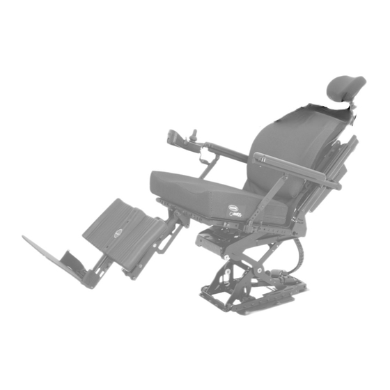
OWNERS MANUAL
DEALER: This manual contains important safety, maintenance and operating
information specific to the operation of our Motion Concepts Power Positioning
System. This Manual MUST be given to the user of the product.
BEFORE using this product, please read through the instructions carefully and
save for future reference.
Advertisement
Table of Contents

Related Manuals for Motion Concepts F Series


Summary of Contents for Motion Concepts F Series
- Page 1 OWNERS MANUAL DEALER: This manual contains important safety, maintenance and operating information specific to the operation of our Motion Concepts Power Positioning System. This Manual MUST be given to the user of the product. BEFORE using this product, please read through the instructions carefully and...
- Page 3 Power Base (Model): ___________________ This manual may not be reproduced or reprinted either partly or completely without previous written consent from Motion Concepts or its statutory representatives. This owner’s manual is compiled from the latest specifications and product information available at the time of publication.
-
Page 4: Table Of Contents
- 4 - TABLE OF CONTENTS: TABLE OF CONTENTS: INTRODUCTION Important Symbols Considerations For Use “F” Series “F” Series Limited Warranty System Identification SAFETY INFORMATION Stability Incline Warnings General Safety Warnings Weight Capacity Flammability Hardware OEM Wiring Harneses and Electronics Motor Vehicle Transportation POWER POSITIONING FUNCTIONS Programming the Wheelchair/Power Positioning System... - Page 5 - 5 - TABLE OF CONTENTS: TABLE OF CONTENTS: 5.2.2 Standard Recline Armrest Adjustments 5.2.3 Cantilever Armrest Adjustments Arm Pads 5.3.1 Modular Arm Pad Installation/Adjustment 5.3.2 Optional Arm Pad Installation 5.3.3 Armrest Extensions Seat Pan Adjustment Independent Front Riggings 5.5.1 Legrest Depth Adjustment 5.5.2 Swing Away Legrests...
-
Page 6: Introduction
Congratulations on your decision to purchase a Motion Concepts F-Series power positioning system. Our goal at Motion Concepts is to provide you with the best possible seating system. Our close work with many health care professionals has given us an understanding of the challenges that you may confront, and has enabled us to design systems that will help to meet your individual positioning needs. -
Page 7: Important Symbols
- 7 - Important Symbols in this Manual Operating your Motion Concepts Seating System safely depends upon your diligence in following the warnings, cautions and information provided in this User Manual. Setting up and operating the system safely also depends on your own good judgement and common sense, as well as that of your provider, caregiver and/or health professional. -
Page 8: Considerations For Use
Motion Concepts. The warranty shall also not apply to a product which has been damaged as a result of unauthorized repairs and/or by circumstances not under the control of Motion Concepts. -
Page 9: System Identification
- 9 - System Identification Each Motion Concepts seating system is identified by a unique serial number, which allows us to trace the production history of the system and better equips us to address any service issues that may occur over the lifetime of the product. -
Page 10: Safety Information
• Your Motion Concepts seating system can be mounted onto the powerbase in various forward and aft positions. Make certain that the position selected provides you with maximum stability over the full range of seating positions. -
Page 11: Incline Warnings
• Consider the seat cushion being used. A thick seat cushion will raise your center of gravity and reduce the wheelchairs stability in all directions. • All Motion Concepts systems are equipped with drive lockouts. Make certain this is set so as not to compromise your stability while driving (refer to Section 4.3: Safety Lockouts and Limits) •... - Page 12 WARNING! Risk of Injury or damage if correct or improper replacement (service) parts are used • Replacement parts for your power positioning system MUST match original Motion Concepts parts • ALWAYS provide the wheelchair serial number to assist in ordering the correct replacement parts (see...
- Page 13 (DLO) limit (refer to Section 4.3: Safety Lockouts & Limit Switches). • Never allow your Motion Concepts power positioning system to be used as a tie-down point in a vehicle. Use only the designated anchoring points on the power wheelchair (see Section 2.8.1) •...
-
Page 14: General Safety Warnings
- 14 - SAFETY INFORMATION SAFETY INFORMATION GENERAL SAFETY WARNINGS! (...cont’d) WARNING! Danger of injury due to improper lifting or dropping of heavy components! • When maintaining, servicing or lifting any part of your power wheelchair, take into account the weight of the individual components, especially the batteries. -
Page 15: Weight Capacity
(PPS) weight capacity. ii) Power Positioning System (PPS) Weight Capacity The weight capacities for our Motion Concepts/F-Series power positioning systems vary depending on the type of seating system module (i.e.; tilt/recline, elevate, scissor lift, etc..) and the type of wheelchair base... -
Page 16: Hardware
2.6 Hardware ARNING! Do not substitute hardware • All hardware used by Motion Concepts in the assembly and installation of our Power Positioning Systems is high strength. Use only the hardware supplied with the seating system. Should you require any replacement hardware for your seating system, please contact our Customer Service Department, or your local authorized Motion Concepts Dealer for assistance. - Page 17 WARNING! Danger of injury and wheelchair damage if the seating system is used as a tie- down point during transport. • Never use any component of the Motion Concepts seating system as a tie-down point to anchor the wheelchair to the transporting vehicle; Use only the designated/labelled anchoring points on the wheelchair base.
-
Page 18: Power Positioning Functions
WARNING! Changes to the drive programme can affect the driving characteristics and tipping stability of the vehicle. • Motion Concepts factory sets all wheelchair systems with a standard drive programme to ensure safe operating limits for the finished system. • Changes to the drive programme (maximum acceleration and deceleration of the wheelchair) must only be carried out by trained Motion Concepts Dealers! Unauthorized adjustments beyond safe operating limits will compromise the limited warranty. -
Page 19: Operating The Power Positioning System Using A Trx Switch
3.3 Operating the Power Positioning System using a TRx Switch Motion Concepts offers a wide range of manually operated push button switches and toggle switches that may be utilized to operate specific motor functions on the power positioning system. To activate a motor/seat function using a TRx switch, simply press and hold the designated push button or toggle switch. -
Page 20: Configuring The Seat Controls: Direct Mode Vs. Toggle Mode
3.4 Configuring the Seat Controls: Direct Mode vs. Toggle Mode TRx Push Buttons, Toggle Switches and Joysticks can be configured to operate in “Direct” mode or “Toggle” mode. Motion Concepts power positioning systems are typically programmed at the factory to meet customer specifications. -
Page 21: Standard F-Series Positioning Functions
- 21 - 3.0 POWER POSITIONING FUNCTIONS 3.0 POWER POSITIONING FUNCTIONS 3.5 Power Positioning Functions Our modular seating systems are designed to provide dealers and therapists with the ultimate in versatility, flexibility and adjustability. Our modular systems can be readily adapted from base to base. -
Page 22: Wheelchair Drive Controls
3.7 Operating Via Specialty Controls Your wheelchair base and your Motion Concepts power positioning systems may be configured to operate via specialty controls such as a Head Array or Sip ‘n Puff control. If your seating system is configured with a specialty control device, please refer to the Owners/Operators Manual (provided by the device manufacturer) for detailed operating instructions. -
Page 23: Electronics
Our Motion Concepts electronics are designed to interface with all power base electronics platforms and specialty drive controls – including PG, Q-Logic, MK6, RNet, Curtis and DX2 There are three key components common to all our electronics: Seat Control Boxes, Wiring Harnesses and Limit Switches/Sensors. -
Page 24: Wiring Harnesses
- 24 - ELECTRONICS ELECTRONICS Feature Overview for M-Series Control Boxes (with Remote Attendant Control): Attendant Controls- the remote operates as an attendant control (and LED display) utilizing the touch switches to scroll through and operate the desired motor functions on the power positioning system. w Motor Speed Control- The remote allows the individual actuator speeds to be adjusted/set independently for both Forward and Reverse directions. -
Page 25: Safety Lockout And Limit Switches
• The angle at which the limit switches/lockouts are set is critical to the safe operation of the power positioning system. • Motion Concepts will not be liable for any injuries or damage sustained when adjustments are made beyond the factory recommended settings. -
Page 26: Elevate Drive Lockout (Dlo) Or Elevate Reduced Drive Speed Limit
- 26 - ELECTRONICS ELECTRONICS 4.3.2 Elevate Drive Lockout (DLO) or Elevate Reduced Drive Speed Limit Seating systems that are configured with a power elevating seat (PES) or scissor lift module may be configured/programmed with either an Elevate Drive Lockout or a Reduced Drive Speed limit. Both limits utilize a microswitch to trigger the seating system into drive lockout or reduced speed drive as soon as the seating system is elevated to a pre-determined height beyond the home (fully retracted) position. -
Page 27: Max Tilt (Tilt/Recline) Limit
Tilt/Recline combined. The function of this switch is to prevent the back angle from extending beyond a maximum pre-set angle. Motion Concepts seating systems are typically preset at the factory to the maximum allowable angle and do not require any further adjustment unless the max. angle needs to be decreased (see Warning! below). -
Page 28: Anti-Tip Latch Limit Switch
- 28 - ELECTRONICS ELECTRONICS 4.3.5 Anti-Tip Latch Limit Switch Certain powerbases may come equipped, or may have anti-tip devices added to the wheelchair in order to ensure stability during tilt, recline or elevating functions. For these powerbases, our electronics are programmed to engage the anti-tips by means of a limit switch. - Page 29 The components/accessories on your wheelchair may differ from those illustrated in this manual. If you have any questions or concerns related to your specific seating system that are not addressed in this Owners Manual, please contact your Service Provider or Motion Concepts directly for further assistance.
-
Page 30: Seating System Comfort Adjustments
- 30 - SEATING SYSTEM COMFORT ADJUSTMENTS SEATING SYSTEM COMFORT ADJUSTMENTS 5.2 Armrests Adjustments WARNING! Before travelling in your wheelchair and/or operating your seating system, always ensure the amrests are securely locked in place. 5.2.1 Basic Tilt Armrest Adjustments: The basic tilt style armest has a telescoping upper armrest to allow height adjustments in 1/2”... -
Page 31: Cantilever Armrest Adjustments
SEATING SYSTEM COMFORT ADJUSTMENTS 5.2.3 Cantilever Armrests Adjustments: Motion Concepts cantilever armrests are available in Tilt style or Recline style. Both styles of cantilever armrests offer a variety of adjustment options; The following sections illustrate the basic adjustments available for each type. - Page 32 - 32 - SEATING SYSTEM COMFORT ADJUSTMENTS SEATING SYSTEM COMFORT ADJUSTMENTS Armrest Angle Adjustment: (...cont’d) Standard Catilever Armrest Set-Up (parallel to seat frame) rotate the cam upward to lower the armrest angle Lowered Catilever Armrest Set-Up Note: above images are shown with the lever lock handle (optional) Range of Adjustment ANTILEVER...
- Page 33 - 33 - 33 - SEATING SYSTEM COMFORT ADJUSTMENTS SEATING SYSTEM COMFORT ADJUSTMENTS ii) C ANTILEVER ECLINE RMRESTS Armrest Angle Configuration Table: Control Lever Adjustments Base Pivot Position Armrest Angle (at Full Recline) Low Pivot Position Raised Pivot Position Cantilever Recline Armrest Adjustment / Set-Up: NOTE: armrest adjustments should be made with the seat placed in the full upright position: Based on users preferred reclined armrest angle, install the pivot plate at one of the following positions: i) Low Pivot Position: armrest remains in a more horizontal position (more parallel with seat frame)
- Page 34 - 34 - SEATING SYSTEM COMFORT ADJUSTMENTS SEATING SYSTEM COMFORT ADJUSTMENTS Cantilever Recline Armrest Adjustment/Set-Up Armrest Receiver Mount Typical set-up places the initial arm- rest angle around 0°(horizontal) when the system is fully upright Cantilever Armrest Tube Control Lever Push Rod Assembly Default Factory Set-Up (left armrest ass’y shown)
-
Page 35: Arm Pads
- 35 - SEATING SYSTEM COMFORT ADJUSTMENTS SEATING SYSTEM COMFORT ADJUSTMENTS 5.3 Arm Pads 5.3.1 Modular Arm Pad - Installation/Adjustment: 1. Using the hardware provided, install the moulded arm pad tray onto the armrest tube in the pre-determined mounting orientation (see Figure 1.0) and arm pad position (see width & depth adjustments below) 2. -
Page 36: Optional Arm Pad Installation
Please refer to Figure 1.0 below for examples of other armpad options available from Motion Concepts. Arm pads are typically installed via two mounting screws, which secure the arm pad to the armrest tube as illustrated below. -
Page 37: Armrest Extensions
- 37 - SEATING SYSTEM COMFORT ADJUSTMENTS SEATING SYSTEM COMFORT ADJUSTMENTS 5.3.3 Armrest Extensions: Armrest extension tubes are also available from Motion Concepts (sold separately) when longer armrest Armrest extension tubes lengths are required. 1. Insert the extension tube into the front of the armrest extension tube tube with the mounting hole aligned vertically (1). -
Page 38: Independent Front Riggings
SEATING SYSTEM COMFORT ADJUSTMENTS 5.5 Independent Front Riggings Motion Concepts offers several styles of independent front riggings for use on our F-Series power positioning systems, ranging from basic manually operated legrests to power operated articulating legrests. The following information is provided as a general reference for the common features and adjustments found on our various legrests. -
Page 39: Swing Away Legrests
- 39 - SEATING SYSTEM COMFORT ADJUSTMENTS SEATING SYSTEM COMFORT ADJUSTMENTS 5.5.2 Swing Away Legrests The swing-away legrest feature is available on certain models of Motion Concept’s individual legrests to pro- vide the clearance necessary for forward transfers in and out of the chair. Our swing-away legrests utilize a user friendly lever handle that locks and unlocks the legrest, allowing the legrest pin to pivot/rotate about the legrest receiver (see examples illustrated below) e.g.;... -
Page 40: Individual Footplates
- 40 - SEATING SYSTEM COMFORT ADJUSTMENTS SEATING SYSTEM COMFORT ADJUSTMENTS 5.5.4 Individual Footplates: OOTPLATES WARNING! Risk of injury and damage • Footplates are designed to support your legs and feet from a seated position in the wheelchair; NEVER stand on footplates when transferring in or out of the wheelchair •... -
Page 41: Center Mount Front Riggings
SEATING SYSTEM COMFORT ADJUSTMENTS 5.6 Center Mount Front Riggings Motion Concepts offers several styles of center mount front riggings for use on our power positioning systems, ranging ranging from basic fixed center mount legrests, to fully power operated articulating center mount legrests. -
Page 42: Center Mount Depth Adjustment
- 42 - SEATING SYSTEM COMFORT ADJUSTMENTS SEATING SYSTEM COMFORT ADJUSTMENTS 5.6.1 Center Mount Depth Adjustments WARNING! Adjustments involving the legrest depth and seat depth may have a significant effect on the overall stability of the wheelchair. The final set-up should be determined based on the stability and driveability requirements of the end user. -
Page 43: Calf Pad Adjustments
OOTPLATE LATFORM All center mount legrests available from Motion Concepts provide a flip-up footplate feature to provide leg and foot clearance when transferring to and from the front of the wheelchair. The footplates or foot platform can be manually raised/flipped-up to remain perpendicular to the ground as indicated below. -
Page 44: Malleable Calf Pad Adjustment
- 44 - SEATING SYSTEM COMFORT ADJUSTMENTS SEATING SYSTEM COMFORT ADJUSTMENTS 5.7.1 Independent Calf Pad Adjustment (...cont’d) Curved calf pads may be adjusted independently on their respective mounting bracket using the mounting screws at the rear of the calf pads. Calf pads may adjusted (for depth, height & angle) to achieve a variety of different configurations. -
Page 45: Back Adjustments
- 45 - SEATING SYSTEM COMFORT ADJUSTMENTS SEATING SYSTEM COMFORT ADJUSTMENTS 5.8 Back Adjustments 5.8.1 Back Angle Adjustments for Tilt Only Systems The tilt back cane angle can be manually adjusted to one of nine preset angles (see image below). There is a total available adjustment range of 40°... -
Page 46: Height Adjustments For Tilt Only Systems
5.8.2 Back Height Adjustments for Tilt Only Systems For systems equipped with a standard Motion Concepts back pan, the back height can be easily adjusted along the length of the tilt back canes if necessary. Infinite height adjustments can be made along the length of the slotted channel in the Tilt Back Mount Block. -
Page 47: Lateral Trunk Support Adjustments
- 47 - SEATING SYSTEM COMFORT ADJUSTMENTS SEATING SYSTEM COMFORT ADJUSTMENTS 5.9 Lateral Trunk Support Adjustments 5.9.1 Maxx Lateral Trunk Support Angle Adjustment MAXX LATERAL Loosen nuts/screws (x2) TRUNK SUPPORT to adjust pad angle (left assembly shown) Infinite Angle Adjustment Range Width Adjustment Pad Depth Adjustment Loosen screws (x2) to... -
Page 48: Headrests
SEATING SYSTEM COMFORT ADJUSTMENTS SEATING SYSTEM COMFORT ADJUSTMENTS 5.11 Headrests A Motion Concepts offers basic and adjustable headrest options for installation onto the wheelchair back cushion. The headrest clamp hardware is designed to install into existing mounting holes in the back pan. -
Page 49: Adjustable Headrest Set-Up And Installation
- 49 - SEATING SYSTEM COMFORT ADJUSTMENTS SEATING SYSTEM COMFORT ADJUSTMENTS 5.10.2 Adjustable Headrest Set-Up and Installation: Installation/Adjustment: 1. Using the hardware provided, align and install the headrest clamp assembly into the existing mounting holes in the back pan. 2. Secure the headrest pad to the horizontal headrest rod via the mounting ring and hardware provided (1). -
Page 50: Types Of Postural Bolts
- 50 - SEATING SYSTEM COMFORT ADJUSTMENTS SEATING SYSTEM COMFORT ADJUSTMENTS 5.11.1 Types of Postural Belts Your wheelchair can be fitted with the following postural belt types. If your wheelchair has been fitted with a different belt to those listed below, please ensure that you have received the manufacturer's documentation with regard to correct fitting and use. -
Page 51: System Installation/ Set-Up/ Adjustment Review
Test drive the wheelchair and operate the power positioning system. Ensure the Owner’s Manual is provided to the end user. If you have any concerns or questions regarding your Motion Concepts Power Positioning System please contact our Techncal Service Department for assistance. -
Page 52: Maintenance Schedule
7.0 GENERAL MAINTENANCE & SAFETY 7.0 GENERAL MAINTENANCE & SAFETY IMPORTANT! Motion Concepts disclaims all responsibility and liability for any personal injury or damage to property that occurs as a result of improper or insufficient maintenance, and/or any unauthorized Dealer or third-party repairs or modifications made to the power positioning system or the wheelchair on which the system is installed. -
Page 53: Safety Inspection Checklist
- 53 - 7.0 GENERAL MAINTENANCE & SAFETY 7.0 GENERAL MAINTENANCE & SAFETY 7.2 Safety Inspection Checklist Item Initially Monthly 6 Months Periodically Batteries load test batteries (individually) ensure batteries are clean (free from corrosion/ moisture/ dirt) ensure connections are tight and clean Electrical / Wiring Harnesses check for pinches or pulls in wiring (over full range of seating system) -
Page 54: Lubrication
IMPORTANT! To maintain the smooth operation of your Power Positioning System, periodical lubrication of the main pivot points is recommended. Motion Concepts Seating Systems are pre-lubricated at the factory, however occassional lubrication using a general purpose oil will help to maintain optimal performance of your seating system. -
Page 55: Battery Charging
- 55 - 7.0 GENERAL MAINTENANCE & SAFETY 7.0 GENERAL MAINTENANCE & SAFETY 7.4 Battery Charging WARNING! For detailed information on charging your powerbase batteries, please be certain to read and follow the instructions provided by the powerbase manufacturer & the battery charger manufacturer. IMPORTANT INFORMATION ON BATTERY CHARGING: •... -
Page 56: No Load Voltage Testing
- 56 - 7.0 GENERAL MAINTENANCE & SAFETY 7.0 GENERAL MAINTENANCE & SAFETY 7.5 Battery Testing (...cont’d) 7.5.2 No Load Voltage Testing Test to determine the state of charge of the battery. Refer to the illustration below for testing instructions. WARNING! Never attempt a voltage measurement with a test lead in the AMP (A) or MILLIAMP (mA) input terminal. -
Page 57: Troubleshooting
- 57 - 8.0 TROUBLESHOOTING 8.0 TROUBLESHOOTING IMPORTANT! For additional troubleshooting information regarding the wheelchair powerbase & electronics, please refer to the Troubleshooting section of the Powerbase Owner’s Manual (provided separately) 8.1 Performance Troubleshooting NOTE: For further assistance on these or any other issues, please contact our Technical Service Department. -
Page 58: Electromagnetic Interference (Emi) Information
WARNING! It is very important that you read this information regarding the possible effects WARNING! of electromagnetic interference on your Motion Concepts power positioning system. In addition, operation of power positioning systems can create electro-magnetic interference, the effect of which cannot be determined. Please make sure to read the associated warnings in the user manual for your wheelchair power base. - Page 59 EMI nearby. CAUTION! Modification of any kind to the electronics of the power positioning system as manufactured by Motion Concepts/Motion Solutions may adversely affect the radio frequency interference immunity (RFI) levels.
- Page 60 CANADA Motion Concepts LP Tel (local): 905-695-0134 84 Citation Drive, Unit 1-7 Tel (toll free): 866-748-7943 Concord, Ontario Fax: 905 695 0138 L4K 3C1 Tech Service: 800-680-4191 info@motionconcepts.com www. www.motionconcepts.com Motion Concepts 700 Ensminger Rd, Suite 112 Tel.: 716-447-0050 Tonawanda, New York...
Need help?
Do you have a question about the F Series and is the answer not in the manual?
Questions and answers