Table of Contents
Advertisement
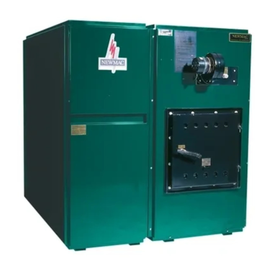
Installation Operating And Service Manual
COMMERCIAL COMBINATION FURNACE
MODELS: CL86-96C,CL86-96G,CL115-170C,CL115-170G
THE INSTALLATION OF THE UNIT SHALL BE IN ACCORDANCE WITH THE REGULATIONS OF THE AUTHORITIES HAVING
JURISDICTION. READ AND SAVE THESE INSTRUCTIONS
United States Stove Company
227 Industrial Park Rd.
South Pittsburg, TN 37380
Email: www.newmacfurnaces.com
Subject to change without notice
Phone: (800)-750-2723
D2210040F-4503i
Advertisement
Table of Contents

Related Manuals for Newmac CL 86C


Summary of Contents for Newmac CL 86C
- Page 1 Installation Operating And Service Manual COMMERCIAL COMBINATION FURNACE MODELS: CL86-96C,CL86-96G,CL115-170C,CL115-170G THE INSTALLATION OF THE UNIT SHALL BE IN ACCORDANCE WITH THE REGULATIONS OF THE AUTHORITIES HAVING JURISDICTION. READ AND SAVE THESE INSTRUCTIONS United States Stove Company 227 Industrial Park Rd. South Pittsburg, TN 37380 Email: www.newmacfurnaces.com Subject to change without notice...
-
Page 2: General Instructions
COMBINATION FURNACES It is the responsibility of the consignee of the unit to examine the packages for damages, and if found, to note the same on the Carrier’ Bill of Lading. PACKAGE # 1 – Heat exchanger with end panels and side panel installed, filters, draft regulator, accessory carton, brick rack, if brick liner, in firebox. - Page 3 1,000 BTU. 1. The NEWMAC COMBINATION FURNACE may be installed with the supply or return air on either side. The units leave the factory with the return or cold air on the right when viewed looking at the oil burner end. If it simplifies the duct installation to have the supply air on the opposite side, remove the installed panel and install it on the other side.
- Page 4 This furnace must be connected to a chimney approved for wood burning appliances , ie. ULC S629 (Canada) and UL103 (US). Newmac recommends an 8” round or 8” square chimney flue (inside dimension), however, this may be reduced to a 7” providing there is enough draft at the appliance to operate as designed. It is the responsibility of the installer to ensure there is sufficient draft in all cases.
-
Page 5: Belt Tension
The WMO-1 switch is required on new Newmac oil-fired and combination furnaces or boilers installed in Canada. It must be installed by a qualified installer in accordance with the manufacturer’s installation instructions. Electrical wiring must be in accordance with applicable codes and the Canadian Electrical Code. -
Page 6: Maintenance And Cleaning
INSTALLATION ON THE BURNER PLATE - COMBINATIONS 1. Remove the 5/8” diameter plug in the burner plate. Cut or file a hole in the rigid fibreglass insulation, behind the 5/8” hole in the burner plate, large enough that the WMO-1 securing nut will seat against the back of the burner plate. - Page 7 Figure 7 - FLUE PIPE CONNECTION & MINIMUM INSTALLATION CLEARANCES...
- Page 8 Figure 8 - CONTROL LOCATIONS Figure 9A Figure 9B Combination Models Cl 115C-170C Firebox Combination Models Cl86c-96C Firebox Installation Procedure With Stainless Steel Front Installation Procedure With Stainless Steel Front...
- Page 9 GRATES CL86G-96G FIREBOX Figure 10A Shipping retainer should be removed to allow grates to turn and shake freely. TO REMOVE A GRATE 1. Remove front casting 2. Slide grate as far forward as possible 3. Lift rear end of grate approximately 6 inches 4.
- Page 10 When the solid fuel thermostat is calling for heat, the draft fan is on. If the fuel has been depleted and cannot keep the temperature up, the oil burner thermostat brings the oil burner on. The NEWMAC COMBINATION FURNACE has a relay that stops the draft fan when the oil burner comes on, making the oil fuel side efficient, and making the furnace operate safely.
-
Page 11: Minimum Maximum
(b) Furnace label illustration DRAFT CONTROL OIL ONLY - SOLID FUEL CLOSED MINIMUM MAXIMUM 11. For safe operating procedures for solid fuel burning, refer to the notice label on the furnace. • The furnace room must have adequate air for combustion. If the unit is in a confined space, on square inch of free air access for every 1,000 BTU must be provided. -
Page 12: Summer Shut Down
SUMMER SHUT DOWN When burner is not to be used during the summer months turn off burner main switch. If the heating unit room is damp, protect burner against dirt and moisture with light cover. SAFETY SHUT-OFF An emergency oil shut-off valve should be installed as required by local ordinance. Always keep the valve shut- off if the burner is shut down for an extended period of time. -
Page 13: Coal Burning Tips
COAL BURNING TIPS Burn ONLY anthracite (hard) coal of the “chestnut” size. Bituminous (soft) coal is not recommended because it has a high ash and sulfur content which means more cleaning and greater pollution. Also bituminous coal produces excessive smoke and an excessive amount of dirt and ash, which will plug the heating unit and the flue pipe possibly causing smoke damage or danger of carbon monoxide poisoning. -
Page 14: Maintenance
Clinker formation can occur from a number of different causes or a combination of causes. Some of these are as follows: • Too hot a fire (too much draft) • Too shallow a bed of coals • Too deep a bed of coals •... - Page 15 • This furnace must be installed according to CSA Standard B139 “Installation Code for Oil Burning Equipment”. Furnace must be installed as per Newmac clearances. Venting must be installed according to CSA Standard B365 “Installation Code for Solid Fuel Burning Appliances and Equipment”.
- Page 16 • For CL115, 140, 155, 170, a minimum supply duct free area of 220, 220, 240, 260 sq. in. respectively, must be maintained at all times during heating the cycle. • For CL115, 140, 155, 170, a minimum return duct free area of 250, 250, 280, 300, sq. in. respectively, must be maintained at all times during heating the cycle.
- Page 17 Figure 11 - TYPICAL A/C COIL INSTALLATION...
- Page 18 Figure 12 - WIRING DIAGRAM WITH AIR CONDITIONING...
- Page 19 Figure 13 - CL SERIES WIRING DIAGRAM...
- Page 20 Figure 14 - COMBINATION AIR FLOW Figure 15 - AIR CONDITIONING INSTALLATION Figure 16B - ELECTRODE SETTING FOR RIELLO Figure 16A - ELECTRODE SETTING FOR AERO AND BECKETT Figure 16C - BURNER INSERTION DIMENSIONAL RELATIONSHIPS AERO & BECKETT RIELLO A 1/8” 5/32”...
-
Page 21: Gas Piping
LP burners are designated by "LP". Example HP 2258-LP-PS. *** Newmac furnaces are not certified in Canada with gas burners installed. Check with local authorities and obtain their approval before installing a power gas burner. Refer to gas burner manual for proper installation and service. - Page 22 STARTING GAS BURNER Figure 17-1D ADAMS GAS BURNER PARTS LIST 1. Be sure cock on combination valve is in "OFF" position for HP225 BPS 5 minutes. Ref DESCRIPTION HP-225 BPS 2. Open gas cock on combination valve to "ON" position. 3.
- Page 23 Figure 17-1E - AERO PGB 220-370 GAS BURNER EXPLODED ASSLY...
- Page 24 Figure. 17-1F - AERO PGB 220-370 GAS BURNER PARTS LIST AERO PGB 220-370 GAS BURNER PARTS LIST ITEM # PART NAME & DESCRIPTION AERO # F Housing 9035222400 Airtube (5"-8"-11') Mounting Flange (Standard) 2735161000 Micro Switch (V3101-D8) 9035061441 Sail & Leaf (JV-26) 2735121091 "J"...
- Page 25 Figure 17-1G - THERMO-DISC MOUNTING ON BURNER PLATE...
- Page 26 Figure 17-2A - AERO BURNER EXPLODED ASSEMBLY...
- Page 27 Figure 17-2B - PARTS LIST Model F-AFC AERO OIL BURNER Model F-AFC AERO OIL BURNER ITEM # DESCRIPTION AERO PART # NEWMAC PART # F housing 2735222100 Blast Tube 8" D2090006 Mounting flange - Standard 2735161000 Air band assembly 2726200100...
- Page 28 Figure 17-3A - BECKETT BURNER EXPLODED ASSEMBLY...
- Page 29 Figure 17-3B - BECKETT BURNER PARTS LIST BECKETT BURNER PARTS LIST PART NUMBER ITEM NO. DESCRIPTION BECKETT NEWMAC 5877 D2090024 Burner Housing Assembly 3709 Air Shutter 3492 Air Band 3493 Escutcheon Plate 21844U D2060012 Pump Clean Cut A2EA - 6520 51843U Strainer &...
- Page 30 Figure 17-4A - RIELLO F3 & F5 EXPLODED ASSEMBLY Figure 17-4B - AERO PGB 220-370 GAS BURNER PARTS LIST PART NUMBER BURNER MODEL ITEM F3 & F5 DESCRIPTION RIELLO NEWMAC C7010002 D2090043 O-ring - pump cover 3002279 Solenoid Coil 3007802...
- Page 31 Figure 18-1A - CL115-170C WOOD/OIL COMBINATION FURNACE ASSEMBLY Figure 18-1B - PARTS LIST – CL115-170C ITEM NO PART NO DESCRIPTION D4120409 Furnace Section Base Panel 610589 Blower Section Side Panel D2030001 Corbel Combustion Chamber 610590 Fan Partition Panel Straight Brick 2 - 1/2” X 4 - 1/2” D5110003 X 9”...
- Page 32 Figure 18-3A - CL115-170G WOOD/OIL COMBINATION FURNACE ASSEMBLY Figure 18-3B - PARTS LIST – CL115-170G ITEM NO PART NO DESCRIPTION D2080021 Ash Door Spacer Gasket 610589 Blower Section Side Panel D2170007 Cast Grate 610590 Fan Partition Panel D5400047 Aero Burner (not shown) 610592 Blower Section Small Panel D2110128...
- Page 33 Figure 18-2A - CL86-96C WOOD/OIL COMBINATION FURNACE ASSEMBLY Figure 18-2B - PARTS LIST – CL86-96C ITEM NO PART NO DESCRIPTION D4120414 Furnace Section Base Panel 610594 Blower Section Side Panel D2030004 Corbel Combustion Chamber 610595 Fan Partition Panel D5110003 Straight Brick 2 - 1/2” X 4 - 1/2” X 9” 28117 Blower Section Small Panel D5400048...
- Page 34 Figure 18-4A - CL86-96G WOOD/OIL COMBINATION FURNACE ASSEMBLY Figure 18-4B - PARTS LIST – CL86-96G ITEM NO PART NO DESCRIPTION D2170007 Cast Grate D5400048 Aero Burner 610594 Blower Section Side Panel D2110126 Beckett Burner 28117 Blower Section Small Panel D4060118 Firedoor Air Chute 610595 Fan Partition Panel...
-
Page 35: Replacement Parts
REPLACEMENT PARTS Figure 19 - REPLACEMENT PARTS Description Newmac Part Number Delhi Twin G9 Blower D2040105 Delhi Twin G10 Blower D2040104 Torin Twin BC916-916-1 **Replacement Shaft & Bearings Available Torin Twin BC1020-1020-1 **Replacement Shaft & Bearings Available Honeywell R8405C Transformer/Relay (Obsolete) - Page 36 Why this concern about allowing the wood to dry? Green or wet wood is undesirable for several reasons. Green or wet wood tends to mildew and rot which causes a significant reduction in the thermal value. When green or wet wood is burned, it may take 20 to 25 percent of the thermal value of the wood heat to evaporate and drive off the moisture which is contained.
- Page 37 formation. The National Fire Prevention Association states that dilution air increases chimney deposits. In any case, the cooling effect of dilution air does decrease the heat transfer through the stovepipe and chimney, thus decreasing the system’s energy efficiency. Creosote formation may also depend on the type of wood burned and on its moisture content. Dry hardwoods have a reputation for generating the least creosote, but the quantity can still be very large.
- Page 38 The NEWMAC COMBINATION OIL AND WOOD FURNACE toasts the wood to charcoal and the charcoal and the charcoal burns to dust leaving a minute amount of residue. From the above heat values, it can be seen that a cord or Hickory wood is equivalent to $ 248.22 (@ 30.0 cents litre) worth of oil, over twice as much as you would...
-
Page 39: Operation
MAINTENANCE AND OPERATING BULLETIN Regarding Multi-fuel and Solid Fuel Burning Heating Units The following are some suggestions with reference to the above: 1. MAINTENANCE - In addition to periodic cleaning, it is most important that the unit be cleaned thoroughly at the end of each heating season. -
Page 40: Important Instructions
IMPORTANT INSTRUCTIONS 1. An emergency power switch is required to be installed in a convenient location at a safe distance from the burner. This switch interrupts the electrical supply circuit to the appliance. Make sure you are aware of its location and the off position is clearly marked. -
Page 41: Installer Information
INSTALLER INFORMATION NAME:___________________________________COMPANY:________________________________ Call (____)__________________ for a service call or for additional information. APPLIANCE INITIAL TEST AND SERVICE INFORMATION MODEL:___________________________ INSTALLATION DATE:______________________________ DATE FUEL INPUT (GPH) FUEL PRESSURE (PSIG) DRAFT @ BREECH DRAFT @ OVERFIRE NOZZLE ANGLE/PATTERN CO2 PERCENT BURNER MODEL FLUE GAS TEMP 0F ROOM TEMP 0F 10 SMOKE DENSITY NO. - Page 42 Blower, motor, controls and/or any other electrical or mechanical components, not manufactured by Newmac, are not warranted by Newmac, but are warranted for a period of one year from date of original installation, by their respective manufacturer. In addition to this comprehensive, unconditional one year, new product warranty, Newmac further warrants the heat exchanger for an additional nine calendar years from date of original installation and in accordance with the declining table as set out below.
Need help?
Do you have a question about the CL 86C and is the answer not in the manual?
Questions and answers