Advertisement
Quick Links
Advertisement

Related Manuals for No Butts Bin SR1588-F


Summary of Contents for No Butts Bin SR1588-F
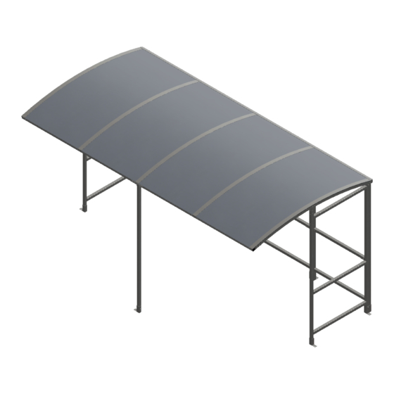
- Page 1 Assembly Instructions Shelter type: SR1588-F SR1588-F-03-21022019-USA...
- Page 2 EXPLODED VIEW Fittings Bolt set M10 AB1210 Black Washer 25mm M10 x 100mm M10 x 60 mm Tech Concrete Bolt screw Pack C+D Required Image...
- Page 3 PARTS LIST ITEM PART DIMENSION DIMENSION IMAGE DESCRIPTION QTY. (MM) (INCHES) FRAME 2000 x 1035 78.74 x 40.55 BRACKET 110 x 110 x 40 4.33 x 4.33 BRACKET 220 x 40 8.66 x 1.57 BRACKET 110 x 42 x 40 4.33 x 1.81 5.51 x 1.57 x STUB...
- Page 4 Step 1 Assemble S1C frames to make up the main structure using CB1 brackets for the corners and JF1 brackets for the straight joints. MEASUREMENTS IN BLUE - MM MEASUREMENTS IN GREEN - INCHES CHECK DIMENSIONS TO ENSURE CORRECT ALIGNMENT Ensure correct alignment on corners...
- Page 5 Step 2 Attach the S1 stubs to the front of the frame using CB1, JF1 and JF3 brackets, then bolt the R4 Rafter into place using the RB1 brackets and the stubs S1 STUB DETAIL A SCALE 1 : 9 S1 STUB DETAIL B SCALE 1 : 6...
- Page 6 Step 3 Assemble the T-section by joining the two ST4 tie bars using a JF3 bracket then join the P4 post using two RB1 brackets and attach a L1 bracket to each end. JF3 ON FRONT RB1 BELOW DETAIL C SCALE 1 : 4...
- Page 7 Step 4 Attach the T-section to the shelter, then fix the R4 rafters in place using more RB1 brackets on the rear and L1 brackets on the front. Bolt the FT1 and F3 brackets to the shelter and move it to its final position before using anchor bolts to secure it to the ground.
- Page 8 Step 5 Stick the sealing strips (SS) to the rafters and line up the ACE2 panels with the outside of the shelter then equally space the ACC2 panels in the gap. Apply more sealing strips on the top of the roof panels directly above the strips on the rafters.
- Page 9 Step 6 Screw down the RC2 strips into the rafter with the 25mm tech screws to secure the roof panels. Push EC40 end caps into any open ends of box section. Screw A3 Angle onto the back edge of the the roof.
- Page 10 PLAN VIEW OVERALL DIMENSIONS AND GROUND FIXING POSITIONS Suggested size for concrete base: 200mm / 7.87in oversized on all four sides. 2183.14 85.97 39.17 41.12 1044.50...
- Page 11 Notes:...
- Page 12 THANK YOU FOR PURCHASING THIS PRODUCT MAINTENANCE: To ensure your products give you many years of use we recommend that you: • Clean panels regularly with soapy water • Ensure all fittings are tight (for example after a big storm) •...