
Related Manuals for Lorex SY14S1044C-A


Summary of Contents for Lorex SY14S1044C-A
- Page 1 14” 4-CHANNEL B&W SWITCHER OBSERVATION SYSTEM MODEL: SY14S1044C-A FOR MORE INFORMATION WWW.SYLVANIACCTV.COM Before operating this system, please read this Manual thoroughly and retain it for future reference!!!
- Page 2 System. Lorex is committed to providing our customers with a high quality, reliable security product that customers have come to expect from us. With the new Lorex system, you are capable of viewing up to 4 camera locations in real time. This system allows you to view Sequential cameras.
- Page 3 NOTE This equipment has been certified and found to comply with the limits regulated by FCC, EMC and LVD. Therefore, it is designed to provide reasonable protection against interference and will not cause interference with other appliance usage. However, it is imperative that user follows this manual's guidelines to avoid improper usage which may result in damage to the unit, electrical shock and fire hazard or injury.
- Page 4 GENERAL PRECAUTIONS 1. Read Instructions - All the safety and operating instructions should be read before the product is operated. 2. Retain Instructions - The safety and operating instructions should be retained for future reference. 3. Heed Warnings - All warnings on the product and in the operating instruction should be adhered to. 4.
- Page 5 18. Object and Liquid Entry - Never push objects of any kind into this product through openings as they may touch dangerous voltage points or short-out parts that could result in a fire or electric shock. Never spill liquid of any kind on the product. 19.
-
Page 6: Table Of Contents
10. APPENDIX - A CONNECTING MONITOR TO STANDARD VCR -------------------------15 11. APPENDIX - B CONNECTING TO SLAVE MONITOR ---------------------------------------16 12. APPENDIX - C CONNECTING TO A LOREX TIME LAPSE VCR FOR ALARM REC. --------------------------------------------------------------------------------------17 13. APPENDIX - D CONNECTING TO A LOREX TIME LAPSE VCR FOR NORMAL REC. -
Page 7: Cautions & Features
CAUTIONS 1. All the warnings and instructions of this manual should be followed 2. Remove the plug from the outlet before cleaning. Do not use liquid aerosol detergents. Use water damped cloth for cleaning 3. Do not use this unit in very humid and wet places 4. -
Page 8: System Includes
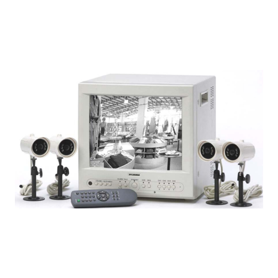
SYSTEM INCLUDES 14” 4-CHANNEL B&W 4 - 1/4” CMOS B/W CAMERAS WITH MONITOR WITH NIGHT VISION, METAL STAND AND REMOTE CONTROL 57 FT CABLE IMPORTANT NOTE : To increase the life of the CRT and to help prevent “burn in” on the monitor, it is strongly recommended that the monitor be set to standby mode when not in use for observation. -
Page 9: Monitor Controls - Front Panel
MONITOR CONTROLS - FRONT PANEL 1. Infra-Red Receiver – Receives signal from remote control to the monitor. 2/3. Volume – Decreases/Increases volume sound. Press “-” to decrease the sound level. Press “+” to increase the sound level. 4. Mute – This button will disable the audio feature from the camera to the monitor. The amber LED light will be on when the Mute button is selected. - Page 10 7. Talk Button – By pressing and holding this button the user has the ability to talk to a specific camera location. This button must be pressed the entire time, while talking. To listen to the camera location release the talk button. Note: This feature is only available with the wired cameras, which have two-way audio feature.
- Page 11 Display Mode - Changes location of screen display (Left/Right and On/Off options). Allows you to remove or activate the camera titles DISPLAY MODE TIME / DATE : DATE TIME TYPE : MM/DD/YY LOSS POSITION: LEFT DISPLAY : ON PUSH ↑↓← →, MENU KEY Alarm Mode - This screen allows you to change Alarm functions (Alarm ON/OFF) individually.
-
Page 12: Monitor Controls - Back Panel
MONITOR CONTROLS - BACK PANEL 1. Power - This button controls power to the entire unit . Depress the side with the ‘•’, to turn power ON. Depress the other side to turn the unit OFF. When the monitor is On, it is defaulted to Channel 1. -
Page 13: Setting Menu
SETTING MENU Features of the Remote Control. For more details on specific remote control features, refer to the Monitor features FUNCTION DESCRIPTION STANDBY Turns unit into Standby Mode Disconnect the audio from the Camera MUTE Allows the user to select individuals cameras Sets monitor to VCR Mode MENU Calls up the Menu Feature... -
Page 14: Standard Wired Camera & Camera Installation
STANDARD WIRED CAMERA Camera Lens – Delivers high quality image by using a 1/4” CMOS Image Sensor LED’s - 6 IR LED’s for night vision Speaker – Delivers sound from the monitor to the camera Camera Input – Connect cable to monitor Bracket –... -
Page 15: Monitor Connections & Trouble Shooting
MONITOR CONNECTIONS 1. Camera 1 Input Connect one end of the supplied 65ft cable to the first wired camera, the other end to camera Input 1. 2. Camera 2 – 4 Inputs Connect optional/additional cameras to the camera 2-4 inputs using either the DIN or BNC camera inputs. -
Page 16: Technical Specifications
TECHNICAL SPECIFICATIONS MONITOR Picture Tube 14” B&W Horizontal resolution 300 lines at center Camera Capable Up to 4 Camera Input 4 DIN / 4 BNC Alarm Inputs/Outputs 4 / 2 Input signal 1V p-p at 75 ohms terminated Power Source Multi-voltage (AC100V –... -
Page 17: Optional Accessories
OPTIONAL ACCESSORIES The following accessories are available to add to your existing system. CABLE TIME LAPSE VCR NIGHTVISION Weatherproof Night vision Extends viewing length Used to record key events. accessory. Allows you to from Camera to monitor. Select From a 40 hour real see in the dark up to 35-40 Available In 65, 100 and time or 960 Hour time lapse... -
Page 18: Appendix - A Connecting Monitor To Standard Vcr
APPENDIX - A CONNECTING MONITOR TO A STANDARD VCR Please see the diagram below for connecting your VCR to the Monitor. NOTE: Ensure the Standard VCR’s channel is set to A/V Mode in order to ensure reception. Consult your VCR’s Owners Manual to set the VCR to this setting. * Important Note: To record the video signal only from the monitor use the VCR Audio/Video out terminals. -
Page 19: Appendix - B Connecting To Slave Monitor
APPENDIX - B CONNECTING TO SLAVE MONITOR Connections to another monitor (e.g. Slave Monitor) can be made through “MONITOR OUT” as shown in the diagram below VIDEO IN AUDIO IN -16-... -
Page 20: Appendix - C Connecting To A Lorex Time Lapse Vcr For Alarm Rec
APPENDIX - C CONNECTING TO A LOREX TIME LAPSE VCR FOR ALARM RECORDING -17-... -
Page 21: Appendix - D Connecting To A Lorex Time Lapse Vcr For Normal Rec
APPENDIX - D LOREX TIME LAPSE VCR CONNECTING TO A FOR NORMAL RECORDING -18-... -
Page 22: Appendix - E Connecting To A Lorex Dvr For Normal Recording
APPENDIX - E LOREX DVR CONNECTING TO A FOR NORMAL RECORDING DVR – Back Panel NOTE When recording to a Digital Video Recorder, the DVR may indicate a Video Loss as the monitor sequences between channels. This Video Loss occurs because the monitor’s switching function is analogue, whereas the DVR is a digital product. -
Page 23: Appendix - F Connecting To A Lorex Dvr For Alarm Recording
APPENDIX - F LOREX DVR CONNECTING TO A FOR ALARM RECORDING NO 8 15 COM To N/O terminal on Monitor 14 A/I NC 7 R/S 6 13 A/R E/O 5 12 D/F S/O 4 11 RX2 10 TX2 V/L 3... -
Page 24: Care And Maintenance
CARE AND MAINTENANCE Please follow the following instructions to ensure proper care and maintenance of this system Keep your monitor and camera dry. If it gets wet, wipe it dry immediately. Use and store your unit in normal temperature environment. Extreme temperatures can shorten the life of the electronic devices.
Need help?
Do you have a question about the SY14S1044C-A and is the answer not in the manual?
Questions and answers