
Related Manuals for Lorex SG15F5584


Summary of Contents for Lorex SG15F5584
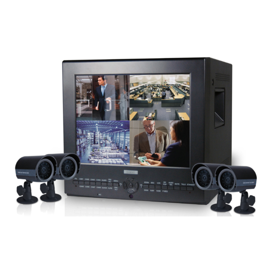
- Page 1 15” FLAT CRT DUAL-QUAD 8 Channel Observation System Instruction Manual English Version 1.0 MODEL: SG15F5584 www.lorexcctv.com © Copyright 2006 LOREX Technology Inc.
- Page 2 Thank you for purchasing the 15” 2 Page/8 Channel Color Quad Observation system. Lorex is commit- ted to providing our customers with a high quality, reliable security product. With this 2 Page Quad system, you are capable of viewing up to 8 camera locations in real time (4 cam- eras per page).
- Page 3 Important Safeguards Important Safeguards In addition to the careful attention devoted to quality standards in the manufacture process of your video product, safety is a major factor in the design of every instrument. However, safety is your responsibility too. This sheet lists important information that will help to assure your enjoyment and proper use of the video product and accessory equipment.
- Page 4 Important Safeguards Service 13. Servicing - Do not attempt to service this video 19. Cleaning - Unplug the video product from the wall equipment yourself as opening or removing covers outlet before cleaning. Do not use liquid cleaners or may expose you to dangerous voltage or other aerosol cleaners.
- Page 5 4. Keep enough space around the unit for ventilation. Slots and openings in the storage cabinet should not be blocked 5. During lightning storms, or when the unit is not used for a long time, disconnect the power supply, antenna, and cables to protect the unit from electrical surge LOREX TECHNOLOGY INC. http://www.lorexcctv.com...
- Page 6 Observation System Features Observation System Features • 15” TRUE FLAT Monitor • Dual Quad Technology allows for viewing of up to 8 cameras • Convenient operation using remote control • 8 camera inputs (8 DIN, 8 BNC and Audio RCA) •...
-
Page 7: Table Of Contents
Table of Contents Table of Contents Getting Started ..................9 SG15F5584 - Front - Primary Function Buttons ......10 - 13 SG15F5584 - Front - Secondary Function Buttons ......14 - 15 SG15F5584 - Back ................16 - 17 Remote Control ..................18 Installing Cameras .................. - Page 8 Table of Contents Motion Set ....................27 MOTION ............................ 27 CHANNEL ..........................27 SENSITIVITY..........................27 AREA ............................28 RETURN ............................ 28 EXIT ............................28 System Set ....................29 KEY BUZZER ..........................29 LOSS BUZZER .......................... 29 QUAD LINE ..........................29 BLANK COLOR .........................
-
Page 9: Getting Started
Getting Started Getting Started The SG15F5584 system comes with the following components: 15” Color 2 Page / 8 Channel Dual Quad Monitor 4 x Camera 4 x 1/4” CCD Color IR Day/Night Cables (57’ Length) Cameras (with Removable Sunshade) Remote Control... -
Page 10: Sg15F5584 - Front - Primary Function Buttons
SG15F5584 - Front - Primary Function Buttons SG15F5584 - Front - Primary Function Buttons 9 10 11 12 13 14 16 17 18 19 21 22 23 24 1. FN (FUNCTION) BUTTON - When this button is pressed, the LED below the button will turn ON indicating that secondary function of the front panel buttons can be activated. - Page 11 SG15F5584 - Front - Primary Function Buttons 4. FRZ ALL BUTTON - The function of the FRZ ALL (Freeze All) button is to digitally freeze the image that is being displayed on the monitor. To freeze an image: • Press the [FRZ] button while viewing a FULL SCREEN single camera in live video. This will freeze the camera image being viewed.
- Page 12 SG15F5584 - Front - Primary Function Buttons 7. ZOOM BUTTON - This monitor is equipped with 2 times digital ZOOM. To utilize this feature proceed as follows: • Set the monitor to full screen mode or Quad mode for the desired channel •...
- Page 13 SG15F5584 - Front - Primary Function Buttons 10 11 12 13 14 10. PIP POP BUTTON - Display a main camera image with secondary camera sub-images: • PIP (Picture In Picture) allows you to view three locations simultaneously, one being the main channel, the others being viewed as small images on the screen.
-
Page 14: Sg15F5584 - Front - Secondary Function Buttons
NOTE: The SECONDARY FUNCTION is enabled if the red LED indicator light is lit (below the FN button). 16. MIC - Enable TWO-WAY AUDIO with select LOREX cameras 17. QUAD 2 BUTTON - Press the [FN] Button (confirm that the red LED below the FN button is lit), then press the [QUAD] button to display the CAM 5- CAM 8 cameras in 4 equal Quadrants on the monitor. - Page 15 SG15F5584 - Front - Secondary Function Buttons 21 22 23 24 21. MAIN BUTTON - Pressing the Main button while in the PIP, Dual PIP or POP mode will change the camera input of the main screen being displayed. 22. SUB 1 BUTTON - Press the FN button to activate the secondary function, then press the SUB 1 button.
-
Page 16: Sg15F5584 - Back
SG15F5584 - Back SG15F5584 - Back 1. POWER SWITCH - This button controls power to the entire unit. Depress the side with the ‘I" to turn power ON. Depress the other side to turn the unit OFF 2. RCA AUDIO INPUTS - Channel 1-8 Audio inputs (for cameras with standard RCA Audio output) 3. - Page 17 SG15F5584 - Back 6. 6 PIN DIN CAMERA INPUTS - Channel 1-8 PIN 1 PIN 6 Camera inputs (for cameras with 6 pin DIN connection). Cameras can be connected using PIN 2 PIN 5 either 6 PIN DIN or BNC (Video) and RCA (Audio) terminals.
-
Page 18: Remote Control
Remote Control Remote Control Listed below is a quick reference for the Remote Control. For details on specific features, refer to the SG15F5584 - Front Panel features on Pages 10-15 STANDBY BUTTON - FRZ #/# Put the unit into Standby... -
Page 19: Installing Cameras
Installing Cameras Installing Cameras The SG15F5584 Observation System includes 4 - 1/4” CCD Color IR Day/Night Indoor/Outdoor Cameras* INFRA-RED LEDs - Provides illumination for low light conditions INPUT CABLE (BACK) - Delivers Video / Audio / Power from the Observation... -
Page 20: Connecting Cameras
Connecting Cameras Connecting Cameras The SG15F5584 Observation System includes 4 x 1/4” Color CCD DIN Cameras. Additional cameras can be added to the 4 additional camera inputs using the DIN or BNC ports. DIN Connected Cameras OBSERVATION SYSTEM 4 x 1/4” COLOR CCD DIN cameras are included with the Observation System. -
Page 21: Main Menu Control
Main Menu Control Main Menu Control Enter the MENU screen by pressing the MENU button. Scroll through the 9 options by pressing the UP and DOWN buttons. To enter a sub-menu, navigate to the option and press the OK button. To exit a SUBMENU, select the RETURN option (and press the OK button) which takes you back to the MAIN MENU. -
Page 22: Time / Date Set
Time / Date Set Time / Date Set This submenu allows you to change the TIME and DATE displayed on the monitor (On Screen Display), and recorded through an optional DVR / VCR. 1. DISP MON - Display the DATE / TIME on the monitor screen. -
Page 23: Sequence Set
Sequence Set Sequence Set This submenu allows you to change the length of time a camera is displayed while the SEQUENCE (SEQ) feature is enabled. When in SEQUENCE mode, the observation monitor cy- cles through available cameras in the sequence shown below. NOTE: If a camera is set to 0 SEC, it will be skipped in the AUTO SEQUENCING. -
Page 24: Pip/Pop Set
PIP/POP Set PIP/POP Set This submenu allows you to change the settings for PIP (Picture IN Picture) and POP (Picture ON Picture). PIP displays small viewing screen(s) superimposed onto the larger main viewing screen,. POP displays small viewing screen(s) along the top or bottom of the larger main viewing screen. 1. -
Page 25: Pop Position
Title Set 4. RETURN - Return to the MAIN MENU. Navigate by pressing the buttons to highlight, and press the OK button to select [PIP/POP SET] 5. EXIT - Return to the camera view. Navigate by pressing the buttons to highlight, and PIP SEQUENCE [SUB] press the OK button to select... -
Page 26: Alarm Set
This submenu allows you to configure the ALARM alert type and duration.This alarm type is used in conjunction with PIR cameras offered by LOREX, but not included with this system. Alternative- ly, you may use an External motion sensor that connects to the monitors’ ALARM BLOCK. Refer to Appendix #6 (Connecting a Motion / Alarm Device) on Page 45. -
Page 27: Motion Set
Motion Set Motion Set This submenu allows you to change the configurations for MOTION detection, using the monitors built-in Pixel Based Motion Detection. 1. MOTION - Sets the motion detection alarm mode. Navigate by pressing the buttons to highlight, and press the OK button to switch [MOTION SET] between MOTION alarm modes: •... -
Page 28: Area
Motion Set 4. AREA - Sets the area for motion detection. Navigate by pressing the buttons to highlight, and press the OK button to set the [MOTION SET] MOTION detection area. Selections include: MOTION [OFF] CHANNEL [CH1/5] [01] [02] SENSITIVITY [02] AREA [00]... -
Page 29: System Set
System Set System Set This submenu allows you to change the general preferences for the OBSERVATION SYSTEM. 1. KEY BUZZER - Sets the audible BUZZER that can be heard when pressing any key to ON or OFF. Navigate by pressing the buttons to [SYSTEM SET] highlight, and press the OK button to select Y or N. -
Page 30: Pan/Tilt
System Set 7. PAN/TILT - Adjust the Pan / Tilt of the camera (PTZ cameras only). Select Y if a PTZ camera is connected. [SYSTEM SET] 8. ALARM OUT - Set to N/O (Normally Open) or set KEY BUZZER to N/C (Normally Closed). LOSS BUZZER 9. -
Page 31: Monitor Set
Monitor Set Monitor Set This submenu allows you to change the picture settings for the OBSERVATION SYSTEM MONITOR. 1. CONTRAST - Adjust the image contrast. Navigate by pressing the buttons to highlight, and [MONITOR SET] press the OK button to select. Press the buttons to change the CONTRAST (maximum of 25). -
Page 32: Troubleshooting
Troubleshooting Troubleshooting When a malfunction occurs, it may not be serious and can be corrected easily. The following describes the most common problems and solutions. Please refer to the following before calling your Observation System dealer Problem: Observation System Unit is not receiving power, or is not powering up Check: •... - Page 33 Troubleshooting Problem: The image on the Observation System is too dark or too bright Check: • Adjust the CONTRAST and BRIGHTNESS of the unit (Refer to the Menu section) Problem: The image on the Observation System does appears, but does not have sound Check: •...
-
Page 34: Observation System Specifications - Appendix #1
Observation System Specifications - Appendix #1 Observation System Specifications - Appendix #1 Picture Tube 15” Full Flat Color CRT Horizontal resolution 400 lines at center Camera Capable Up to 8 Cameras QUAD Speed 30 FPS Camera Input 8 DIN / 8 BNC Alarm Inputs/Outputs 8 Inputs / 1 Output Input Signal... -
Page 35: Camera Specifications - Appendix #2
Weather Proof Rating IP44 Operating Humidity 90% RH max. As our products are subject to continuous improvement, LOREX Technology Inc. and its subsidiaries reserve the right to modify product design, specifications and prices, without notice and without incurring any obligation. E&OE... -
Page 36: Connecting To A Single Channel Dvr / Vcr - Appendix #3
Connecting to a Single Channel DVR / VCR - Appendix #3 Connecting to a Single Channel DVR / VCR - Appendix #3 The SG15F5584 Observation System can be used with a Single Channel DVR or VCR unit (not included) 1. Connect the Video cable from the... -
Page 37: Connecting To A Multi-Channel Dvr - Appendix #4
Connecting to a Multi-Channel DVR - Appendix #4 Connecting to a Multi-Channel DVR - Appendix #4 The SG15F5584 Observation System can be used with a Multi-Channel DVR (not included). A Multi-Channel DVR enables you to record multiple video streams with a single device... -
Page 38: Connecting A Slave Monitor - Appendix #5
Connecting a Slave Monitor - Appendix #5 Connecting a Slave Monitor - Appendix #5 Connections to a Slave Monitor (not included) can be made through the SLAVE OUT ports on the back of the Observation System A Slave Monitor is used as a View OBSERVATION SYSTEM Only device. -
Page 39: Connecting Motion / Alarm Device - Appendix #6
Connecting Motion / Alarm Device - Appendix #6 Connecting Motion / Alarm Device - Appendix #6 Motion detection and Alarm controls are enabled through the Menu system on the Observation System. Additional motion sensor devices can be connected to the system (Motion Sensors, Door/Window Sensors). -
Page 40: Full Connectivity Diagram - Appendix #7
Full Connectivity Diagram - Appendix #7 Full Connectivity Diagram - Appendix #7 The following diagram outlines a general set of connections available with the SY15F6584 Observation System. OBSERVATION SYSTEM SENSOR (Not Included) 4 x 1/4” CCD CAMERAS (Included) SLAVE MONITOR (Not Included) DVR UNIT (Not Included) -
Page 41: Optional Accessories
Optional Accessories Optional Accessories The following accessories are available to add to your existing system CABLE DVR UNIT QUAD LOOPING OUTPUT CABLE Extends the length Accessory DVR units - Record Connects 4 video outputs between the CAMERA and Replay from your of a multi-channel CCTV and MONITOR. - Page 42 It’s all on the web Product Information Specification Sheets User Manuals Software Upgrades Quick Start Guides Firmware Upgrades VISIT www.lorexcctv.com wwwlorexcctv.com Strategic Vista International Inc.
Need help?
Do you have a question about the SG15F5584 and is the answer not in the manual?
Questions and answers