Table of Contents
Advertisement
Quick Links
Advertisement
Table of Contents

Related Manuals for Rosewill RNX-N400LX


Summary of Contents for Rosewill RNX-N400LX
- Page 1 User's Manual of WLAN Broadband router (1T2R) USER MANUAL 1.0.0 © 2009...
-
Page 2: Table Of Contents
Table of Contents Chapter I Chapter II Terminology Chapter III Introduction 1. Package contents ........................... 7 2. Product Specifications ........................... 7 3. Product Features ........................... 8 4. Front Panel Description ........................... 9 5. Rear Panel Description ........................... 10 Chapter IV Installation 1. - Page 3 3.18 Firew all - DMZ ................................. 47 3.19 Managem ent - Statistics ................................. 48 3.20 Managem ent - DDNS ................................. 49 3.21 Managem ent - Tim e Zone Setting ................................. 50 3.22 Managem ent - Denial-of-Service ................................. 51 3.23 Managem ent - Log .................................
- Page 4 32. What is Modulation Coding Scheme (MCS)? ........................... 60 33. What is Frame Aggregation? ........................... 61 34. What is Guard Intervals (GI)? ........................... 61 Chapter VII Configuration examples 1. Example one - PPPoE on the WAN ........................... 62 2. Example two - fixed IP on the WAN ...........................
-
Page 5: Fcc
Federal Communications Commission (FCC) Statement 15.21 You are cautioned that changes or modifications not expressly approved by the part responsible for compliance could void the user’s authority to operate the equipment. 15.105(b) This equipment has been tested and found to comply with the limits for a Class B digital device, pursuant to part 15 of the FCC rules. - Page 6 Access Point Complementary Code Keying CSMA/CA Carrier Sense Multiple Access/Collision Avoidance CSMA/CD Carrier Sense Multiple Access/Collision Detection DDNS Dynamic Domain Name Server Diffie-Hellman Algorithm DHCP Dynamic Host Configuration Protocol DSSS Direct Sequence Spread Spectrum Extensible Authentication Protocol Encapsulating Security Payload Federal Communications Commission File Transfer Protocol IEEE...
-
Page 7: Chapter Iii Introduction
Introduction Introduction The Wireless LAN Broadband Router is an affordable IEEE 802.11b/g with 802.11n Draft 2.0 specifications of wireless LAN broadband router solution; setting SOHO and enterprise standard for high performance, secure, manageable and reliable WLAN. This document describes the steps required for the initial IP address assign and other WLAN router configuration. -
Page 8: Product Features
Product Features Generic Router Ø Compatible with IEEE 802.11n Draft 2.0 Specifications provides wireless speed up to 150Mbps data rate. Ø Compatible with IEEE 802.11g high rate standard to provide wireless Ethernet speeds of 54Mbps data rate. Ø Maximizes the performance and ideal for media-centric applications like streaming video, gaming and Voice over IP technology. -
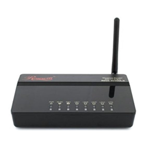
Page 9: Front Panel Description
Introduction Front Panel Description LED Indicator State Description 1. PWR LED The WLAN Broadband Router is powered on. The WLAN Broadband Router is powered off. 2. WLAN LED Flashing Data is transmitting or receiving on the antenna. No data is transmitting or receiving on the antenna. 3. -
Page 10: Rear Panel Description
Rear Panel Description Interfaces Description Antenna (Fixed / SMA) The Wireless LAN Antenna. Power The power jack allows an external DC power supply connection. The external DC adaptor provide adaptive power requirement to the WLAN Broadband Router. The RJ-45 sockets allow LAN connection through Category 5 cables. -
Page 11: Software Installation
Installation Software Installation There are no software drivers, patches or utilities installation needed, but only the configuration setting. Please refer to chapter 3 for software configuration. Notice: It will take about 50 seconds to complete the boot up sequence after powered on the WLAN Broadband Router;... -
Page 12: Connect To The Wlan Broadband Router
ü IP Address: 192.168.1.1, any IP address within 192.168.1.1 to 192.168.1.253 is good to connect the Wireless LAN Access Point. ü IP Subnet Mask: 255.255.255.0 5. Click OK to complete the IP parameters setting. For OS of Microsoft Windows 95/ 98/ Me: 1. -
Page 13: Management And Configuration On The Wlan Broadband Router
Software configuration Management and configuration on the WLAN Broadband Router 5.3.1 Status This page shows the current status and some basic settings of the device, includes system, wireless, Ethernet LAN and WAN configuration information. Item Description System Uptime It shows the duration since WLAN AP Router is powered on. Firmware version It shows the firmware version of WLAN AP Router. - Page 14 Wireless configuration Mode It shows wireless operation mode Band It shows the current wireless operating frequency. SSID It shows the SSID of this WLAN AP Router. The SSID is the unique name of WLAN AP Router and shared among its service area, so all device sat tempts to join the same wireless network can identify it.
-
Page 15: Setup Wizard
Software configuration 5.3.2 Setup Wizard This page guides you to configure wireless broadband router for first time. I. Operation Mode This page followed by Setup Wizard page to define the operation mode. -15-... - Page 16 II. Time Zone Setting This page is used to enable and configure NTP client. III. LAN Interface Setup This page is used to configure local area network IP address and subnet mask. IV. WAN Interface Setup This page is used to configure WAN access type. -16-...
- Page 17 Software configuration V. Wireless Basic Settings This page is used to configure basic wireless parameters like Band, Mode, Network Type SSID, Channel Number, Enable Mac Clone(Single Ethernet Client). VI. Wireless Security Setup -17-...
- Page 18 This page is used to configure wireless security. -18-...
-
Page 19: Operation Mode
Software configuration 5.3.3 Operation Mode This page is used to configure which mode wireless broadband router acts. Item Description Gateway Traditional gateway configuration. It always connects internet via ADSL/Cable Modem. LAN interface, WAN interface, Wireless interface, NAT and Firewall modules are applied to this mode Bridge Each interface (LAN, WAN and Wireless) regards as bridge. - Page 20 Item Description Disable Wireless LAN Interface Click on to disable the wireless LAN data transmission. Band Click to select 2.4GHz(B) / 2.4GHz(G) / 2.4GHz(N) / 2.4GHz(B+G)/ 2.4GHz(G+N) / 2.4GHz(B+G+N) Mode Click to select the WLAN AP / Client / WDS / AP+WDS wireless mode.
-
Page 21: Wireless - Advanced Settings
Software configuration Channel Number Select the wireless communication channel from pull- down menu. Broadcast SSID Click to enable or disable the SSID broadcast function. Click Enabled/Disabled to init WMM feature. Data Rate Select the transmission data rate from pull-down menu. Data rate can be auto-select, 1M to 54Mbps or MCS. -
Page 22: Wireless - Security Setup
Item Description Fragment Threshold Set the data packet fragmentation threshold, value can be written between 256 and 2346 bytes. RTS Threshold Set the RTS Threshold, value can be written between 0 and 2347 bytes. Beacon Interval Set the Beacon Interval, value can be written between 20 and 1024 ms. - Page 23 Software configuration Item Description Select SSID Select the SSID from multiple APs. Encryption Select the encryption supported over wireless access. The encryption method can be None, WEP, WPA, WPA2 or WPA-Mixed. Use 802.1x While Encryption is selected to be WEP. Click the check box Authentication to enable IEEE 802.1x authentication function.
-
Page 24: Wireless - Access Control
64-bit 128-bit ASCII 5 characters 13 characters 10 hexadecimal codes 26 hexadecimal codes 5.3.7 Wireless - Access Control If you enable wireless access control, only those clients whose wireless MAC addresses are in the access control list will be able to connect to your Access Point. When this option is enabled, no wireless clients will be able to connect if the list contains no entries. -
Page 25: Wds Settings
Software configuration previous configuration setting. Current Access It shows the registered clients that are allowed to link to this Control List WLAN Broadband Router. Delete Selected Click to delete the selected clients that will be access right removed from this WLAN Broadband Router. Delete All Click to delete all the registered clients from the access allowed list. -
Page 26: Wds Security Setup
Apply Changes Click the Apply Changes button to complete the new configuration setting. Reset Click the Reset button to abort change and recover the previous configuration setting. Set Security Click button to configure wireless security like WEP(64bits), WEP(128bits), WPA(TKIP), WPA2(AES) or None Show Statistics It shows the TX, RX packets, rate statistics. -
Page 27: Wds Ap Table
Software configuration 5.3.8.2 WDS AP Table This page is used to show WDS statistics. Item Description MAC Address It shows the MAC Address within WDS. Tx Packets It shows the statistic count of sent packets on the wireless LAN interface. Tx Errors It shows the statistic count of error sent packets on the Wireless LAN interface. -
Page 28: Site Survey
5.3.9 Site Survey This page is used to view or configure other APs near yours. Item Description SSID It shows the SSID of AP. BSSID It shows BSSID of AP. Channel It show the current channel of AP occupied. Type It show which type AP acts. - Page 29 Software configuration Item Description Disable WPS Click on to disable the Wi-Fi Protected Setup function. WPS Status Show WPS status is Configured or UnConfigured. Self-PIN Number Fill in the PIN Number of AP to register the wireless distribution system access capability. Push Button The Start PBC button provides tool to scan the wireless Configuration...
-
Page 30: Lan Interface Setup
5.3.11 LAN Interface Setup This page is used to configure the parameters for local area network that connects to the LAN ports of your WLAN Broadband Router. Here you may change the setting for IP address, subnet mask, DHCP, etc. Item Description IP Address... -
Page 31: Static Dhcp Setup
Software configuration Static DHCP Select enable or disable the Static DHCP function from pull-down menu. [Server mode only] Set Static DHCP Manual setup Static DHCP IP address for specific MAC address. [Server mode only] Domain Name Assign Domain Name and dispatch to DHCP clients. It is optional field. -
Page 32: Wan Interface Setup
Reset Click the Reset button to abort change and recover the previous configuration setting. Static DHCP List It shows IP Address MAC Address from the Static DHCP. Delete Selected Click to delete the selected clients that will be removed from the Static DHCP list. Delete All Click to delete all the registered clients from the Static DHCP list. -
Page 33: Static Ip
Software configuration 5.3.12.1 Static IP Item Description Static IP Click to select Static IP support on WAN interface. There are IP address, subnet mask and default gateway settings need to be done. IP Address If you select the Static IP support on WAN interface, fill in the IP address for it. - Page 34 interface, fill in the default gateway for WAN interface out going data packets. MTU Size Fill in the mtu size of MTU Size. The default value is 1400. DNS 1 Fill in the IP address of Domain Name Server DNS 2 Fill in the IP address of Domain Name Server DNS 3 Fill in the IP address of Domain Name Server...
-
Page 35: Dhcp Client
Software configuration 5.3.12.2 DHCP Client Item Description DHCP Client Click to select DHCP support on WAN interface for IP address assigned automatically from a DHCP server. Host Name Fill in the host name of Host Name. The default value is empty. MTU Size Fill in the mtu size of MTU Size. - Page 36 Please select Set DNS Manually if the DHCP support is selected. Set DNS Manually Click to select getting DNS address for DHCP support. DNS 1 Fill in the IP address of Domain Name Server DNS 2 Fill in the IP address of Domain Name Server DNS 3 Fill in the IP address of Domain Name Server Clone MAC Address...
-
Page 37: Pppoe
Software configuration 5.3.12.3 PPPoE Item Description PPPoE Click to select PPPoE support on WAN interface. There are user name, password, connection type and idle time settings need to be done. -37-... - Page 38 User Name If you select the PPPoE support on WAN interface, fill in the user name and password to login the PPPoE server. Password If you select the PPPoE support on WAN interface, fill in the user name and password to login the PPPoE server.
- Page 39 Software configuration address to be cloned. Enable uPNP Click the checkbox to enable uPNP function. Enable IGMP Proxy Click the checkbox to enable IGMP Proxy. Enable Ping Access on WAN Click the checkbox to enable WAN ICMP response. Enable Web Server Access on Click the checkbox to enable web configuration from WAN side.
-
Page 40: Pptp
5.3.12.4 PPTP Enter topic text here. Item Description PPTP Allow user to make a tunnel with remote site -40-... - Page 41 Software configuration directly to secure the data transmission among the connection. User can use embedded PPTP client supported by this router to make a VPN connection. Enable Dynamic Mode Click to select PPTP Dynamic support on WAN interface for IP address assigned automatically from a PPTP server.
-
Page 42: Firewall - Port Filtering
Enable Ping Access on WAN Click the checkbox to enable WAN ICMP response. Enable Web Server Access on Click the checkbox to enable web configuration from WAN side. Enable IPsec pass through on VPN Click the checkbox to enable IPSec packet connection pass through. -
Page 43: Firewall - Ip Filtering
Software configuration Item Description Enable Port Filtering Click to enable the port filtering security function. Port Range Protocol To restrict data transmission from the local network Comments on certain ports, fill in the range of start-port and end- port, and the protocol, also put your comments on it. The Protocol can be TCP, UDP or Both. -
Page 44: Firewall - Mac Filtering
Item Description Enable IP Filtering Click to enable the IP filtering security function. Local IP Address To restrict data transmission from local network on Protocol Comments certain IP addresses, fill in the IP address and the protocol, also put your comments on it. The Protocol can be TCP, UDP or Both. -
Page 45: Firewall - Port Forwarding
Software configuration Item Description Enable MAC Filtering Click to enable the MAC filtering security function. MAC Address To restrict data transmission from local network on Comments certain MAC addresses, fill in the MAC address and your comments on it. Comments let you know about whys to restrict data from the MAC address. - Page 46 Item Description Enable Port Click to enable the Port Forwarding security function. Forwarding Local IP Address To forward data packets coming from WAN to a Protocol Port Range specific IP address that hosted in local network Comment behind the NAT firewall, fill in the IP address, protocol, port range and your comments.
-
Page 47: Firewall - Url Filtering
Software configuration 5.3.17 Firewall - URL Filtering URL Filtering is used to restrict users to access specific websites in internet. Item Description Enable URL Filtering Click to enable the URL Filtering function. URL Address Add one URL address. Apply Changes Click the Apply Changes button to save settings. -
Page 48: Management - Statistics
Item Description Enable DMZ Click to enable the DMZ function. DMZ Host IP Address To support DMZ in your firewall design, fill in the IP address of DMZ host that can be access from the WAN interface. Apply Changes Click the Apply Changes button to register the IP address of DMZ host. -
Page 49: Management - Ddns
Software configuration Item Description Wireless LAN Sent Packets It shows the statistic count of sent packets on the wireless LAN interface. Received Packets It shows the statistic count of received packets on the wireless LAN interface. Ethernet LAN Sent Packets It shows the statistic count of sent packets on the Ethernet LAN interface. -
Page 50: Management - Time Zone Setting
Enable DDNS Click the checkbox to enable DDNS service. Service Provider Click the drop down menu to pickup the right provider. Domain Name To configure the Domain Name. User Name/Email Configure User Name, Email. Password/Key Configure Password, Key. Apply Change Click the Apply Changes button to save the enable DDNS service. -
Page 51: Management - Denial-Of-Service
Software configuration Refresh Click the refresh the current time shown on the screen. 5.3.22 Management - Denial-of-Service This page is used to enable and setup protection to prevent attack by hacker’s program. It provides more security for users. -51-... -
Page 52: Management - Log
Item Description Enable DoS Prevention Click the checkbox to enable DoS prevention. Whole System Flood / Enable and setup prevention in details. Per-Source IP Flood… Select ALL Click the checkbox to enable all prevention items. Clear ALL Click the checkbox to disable all prevention items. Apply Changes Click the Apply Changes button to save above settings. -
Page 53: Management - Upgrade Firmware
Software configuration Only show Denial-of-Service log Enable Remote Log Click the checkbox to enable remote log service. Log Server IP Address Input the remote log IP address. Apply Changes Click the Apply Changes button to save above settings. Refresh Click the refresh the log shown on the screen. Clear Clear log display screen. -
Page 54: Management - Save/ Reload Settings
5.3.25 Management - Save/ Reload Settings This page allows you save current settings to a file or reload the settings from the file that was saved previously. Besides, you could reset the current configuration to factory default. Item Description Save Settings to File Click the Save button to download the configuration parameters to your personal computer. -
Page 55: Frequently Asked Questions (Faq)
Software configuration New Password Fill in the password for web management login control. Confirmed Because the password input is invisible, so please fill in the Password password again for confirmation purpose. Apply Changes Clear the User Name and Password fields to empty, means to apply no web management login control. -
Page 56: What Is Bssid
Example 1: wireless Infrastructure Mode Ad hoc mode (also called peer-to-peer mode or an Independent Basic Service Set, or IBSS) is simply a set of 802.11 wireless stations that communicate directly with one another without using an access point or any connection to a wired network. This mode is useful for quickly and easily setting up a wireless network anywhere that a wireless infrastructure does not exist or is not required for services, such as a hotel room, convention center, or airport, or where access to the wired network is barred (such as for consultants at a client site). -
Page 57: What Are The Open System And Shared Key Authentications
FREQUENTLY ASKED QUESTIONS (FAQ) ü Minimizing the number of walls and ceilings. ü Position the WLAN antenna for best reception. ü Keep WLAN devices away from other electrical devices, eg: microwaves, monitors, electric motors, … etc. ü Add additional WLAN Access Points if necessary. What are the Open System and Shared Key authentications? IEEE 802.11 supports two subtypes of network authentication services: open system and shared key. -
Page 58: What Is Beacon Interval
This setting is useful for networks with many clients. With many clients, and a high network load, there will be many more collisions. By lowering the RTS threshold, there may be fewer collisions, and performance should improve. Basically, with a faster RTS threshold, the system can recover from problems faster. -
Page 59: What Is 802.1X Authentication
FREQUENTLY ASKED QUESTIONS (FAQ) 6.17 What is 802.1x Authentication? 802.1x is a framework for authenticated MAC-level access control, defines Extensible Authentication Protocol (EAP) over LANs (WAPOL). The standard encapsulates and leverages much of EAP, which was defined for dial-up authentication with Point-to-Point Protocol in RFC 2284. Beyond encapsulating EAP packets, the 802.1x standard also defines EAPOL messages that convey the shared key information critical for wireless security. -
Page 60: What Is Clone Mac Address
6.24 What is Clone MAC Address? Clone MAC address is designed for your special application that request the clients to register to a server machine with one identified MAC address. Since that all the clients will communicate outside world through the WLAN Broadband Router, so have the cloned MAC address set on the WLAN Broadband Router will solve the issue. -
Page 61: What Is Frame Aggregation
FREQUENTLY ASKED QUESTIONS (FAQ) events. 6.33 What is Frame Aggregation? Every 802.11 packet, no matter how small, has a fixed amount of overhead associated with it. Frame Aggregation combines multiple smaller packets together to form one larger packet. The larger packet can be sent without the overhead of the individual packets. -
Page 62: Configuration Examples
Configuration examples Example one - PPPoE on the WAN Sales division of Company ABC likes to establish a WLAN network to support mobile communication on sales’ Notebook PCs. MIS engineer collects information and plans the WLAN Broadband Router implementation by the following configuration. WAN configuration:PPPoE User Name 84549386... - Page 63 Configuration examples 2. Configure the LAN interface: Open LAN Interface Setup page, enter the IP Address “192.168.1.254”, Subnet Mask “255.255.255.0”, Default Gateway “0.0.0.0”, enable DHCP Server, DHCP client range “192.168.1.100” to “192.168.1.200”. Press button to confirm the configuration setting. -63-...
- Page 64 3. Configure the WLAN interface: Open WLAN Interface Setup page, enter the SSID “AP”, Channel Number “11”. Press button to confirm the configuration setting. -64-...
-
Page 65: Example Two - Fixed Ip On The Wan
Configuration examples Example two - fixed IP on the WAN Company ABC likes to establish a WLAN network to support mobile communication on all employees’ Notebook PCs. MIS engineer collects information and plans the WLAN Broadband Router implementation by the following configuration. WAN configuration:Fixed IP IP Address 192.168.2.254... - Page 66 WLAN configuration: SSID Channel Number 1. Configure the WAN interface: Open WAN Interface Setup page, select Fixed IP then enter IP Address “192.168.2.254”, subnet mask “255.255.255.0”, Default gateway “192.168.2.10”. Press button to confirm the configuration setting. 2. Configure the LAN interface: Open LAN Interface Setup page, enter the IP Address “192.168.1.254”, Subnet Mask “255.255.255.0 ”, enable DHCP Server, DHCP client range “192.168.1.100”...
- Page 67 Configuration examples Press button to confirm the configuration setting. 3. Configure the WLAN interface: Open WLAN Interface Setup page, enter the SSID “AP”, Channel Number “11”. Press button to confirm the configuration setting. -67-...
- Page 68 -68-...
Need help?
Do you have a question about the RNX-N400LX and is the answer not in the manual?
Questions and answers