Advertisement
Quick Links
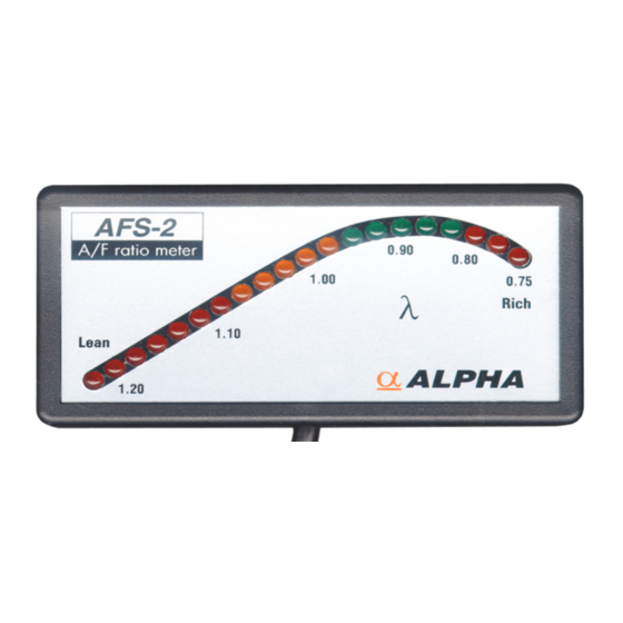
AFS-2 AIR FUEL RATIO METER / SENSOR
The Air-fuel Ratio
The AFS-2 air fuel ratio meter has been developed to measure the air fuel
ratio of petrol engines. It is very important to measure the air-fuel ratio
when seeking maximum engine performance or alternatively, good fuel
economy.
The function of the AFS-2 is based on the measurement of the amount of
oxygen present in the exhaust gas, and is dependent on the air-fuel ratio.
The difference in the oxygen content between the exhaust gas and the
open-air causes a varience in voltage at the Lambda sensor (oxygen sensor).
This voltage difference, which reflects the air-fuel ratio, is sent to the meter
where it is converted to a -value (Lambda).
The
-value reflects the amount of air, in kilograms (kg), per 1 kg fuel
compared to the ideal (stoichiometric) ratio, which is 14.7 parts air per 1
part fuel. The -value 1.00, means that there is 14.7 kg air per 1 kg fuel in
the air-fuel mixture. A rich air-fuel ratio means that there is less than 14.7
kg air per 1 kg fuel and the
ratio means that there is more than 14.7 kg air per 1 kg fuel and the -value
is greater than 1.00.
For example:
13.2 kg air
Lambda ( ) =
14.7 kg air (ideal)
Installation Of Meter
The meter can be fastened using Velcro tapes, which are included in this
kit. This method of installation will allow the meter to be quickly and easily
removed and reinstalled if required.
Clean the mounting surface carefully before installation (remove all traces
of grease and dirt).
The meter can also be fastened with a mounting flange using bolts or screws
(not included). Do note that the end of the screw or bolt must not extend
further than 7mm from the inner surface of the back cover.
Instructions for wiring
1. Connect red (+) to the positive power supply, which must be protected
with a fuse, (a 7.5 Amp fuse, fuse holder, 2 x male lucar connectors and
2 x insulation cover (for the lucars) are supplied in this kit).
2. Connect black (-) to earth (ground), directly to the negative battery
terminal if possible.
Connector pinout
Pin 1: Heater
(+)
White
Pin 2: Heater ground (-)
White
Pin 3: Signal ground (-)
Grey
Pin 4: Sensor signal (+)
Black
Installation Of The Sensor
1. Ensure that the engine and exhaust is cold.
2. Drill a 16mm hole into the exhaust pipe as close as possible to the
engine ( See diagram below Lmin = 0.5m (20") or longer).
3. Place the sensor boss over the hole and check that the hole is big
enough for the sensor. Weld all around the boss. Check that there is no
leak in the seam or the exhaust pipe.
4. Install the sensor into the sensor boss. The kit
contains a plug that can be used when the sensor
is removed.
5. Tighten the sensor to a torque of 50Nm.
-value is smaller than 1.00. A lean air-fuel
= 0.9 (rich)
Notes
-
The signal wire connectors must always be protected against short
circuits to earth (ground).
-
Do not locate the signal wires near the ignition leads as interference
may cause inaccurate meter readings.
-
Leaded fuel can be used, but will slow the sensor reaction rate and will
ultimately lead to sensor failure.
-
The sensor can be used for the tuning of two-stroke engines, but may
become sooty when used for long periods of time.
-
The exhaust gas must reach a temperature of 200°C before the sensor
starts to operate. Usually it takes 1 to 3 minutes to reach that
temperature.
Instructions For Use
When the power is applied, about half of the LED's on the bar should be lit.
When the exhaust gas reaches a temperature of 300°C, the LED-bar starts
to operate (if the air-fuel ratio is lean, fewer LED's are lit, or if it is rich, the
number ot lit LED's increases). After the sensor has reached normal
operating temperature (600°C), the LED-bar on the meter shows the correct
air-fuel ratio (Lambda-value).
Warm up the engine to it's normal operating temperature, before starting to
measure. Load the engine, so that the sensor becomes sufficiently warm
(for example, carry out a few full throttle accelerations).
On deceleration, all the LED's may switch off. This simply means that the
air-fuel ratio becomes extremely lean during deceleration. When the
accelerator is depressed quickly, the LED-bar may indicate a richer mixture
for a short time. This means that the air-fuel ratio moves to the rich-side for
a while as the acceleration enrichment circuit provides extra fuel.
This diagram will help you choose the air-fuel ratio that best fits your
application. The curves illustrate the effect of the variation of the air-fuel
ratio of power output, fuel consumption and carbon monoxide emissions.
Power
Green LED's #13-17 indicate the best ratio when seeking power. Usually
maximum horsepower is achieved when the second or third green LED is
lit. Turbo-charged and racing engines may need a richer air-fuel mixture in
order to prevent excessive cylinder temperature, which may damage the
engine.
Red LED's #18-20 indicate a very rich mixture, which means poor fuel
economy and loss of power.
Fuel Economy
Red LED's #1-7 indicate a lean air-fuel mixture. LED's #6-7 indicate the
best ratio when seeking to obtain low fuel consumption. LED's #1-5 indicate
a very lean air-fuel mixture, which may damage a normal engine.
Emissions
When the 11
th
LED is lit, the Lambda-value is 1.00 and then the air-fuel ratio
is stoichiometric. The yellow LED's are close to the Lambda-value 1.00,
which is the best ratio if seeking low emissions.
L
E
1
6
8
1
3
1
8
1 of 2
D
#
D
e
s
c
i r
t p
o i
n
-
5
V
e
y r
L
e
a
n
-
7
L
e
a
n
E (
c
o
n
o
m
) y
-
1
2
S
o t
c i
h
o i
m
e
r t
c i
-
1
7
R
c i
h
P (
o
w
e
) r
-
2
0
V
e
y r
R
c i
h
8
th
January 2001/FL0393-AFS-2-7p5.pdf
Advertisement

Related Manuals for Alpha AFS-2


Summary of Contents for Alpha AFS-2
- Page 1 The Air-fuel Ratio starts to operate. Usually it takes 1 to 3 minutes to reach that The AFS-2 air fuel ratio meter has been developed to measure the air fuel temperature. ratio of petrol engines. It is very important to measure the air-fuel ratio...
- Page 2 Lambda Sensor Mounting Boss 9990200800 Mounting Boss Blanking Plug WLS181 Lambda Sensor 9990296800 Lambda Display (Large) FL0393-AFS-2-7p5.pdf Fitting Instructions 9990249600 Alpha Sticker Webcon UK Limited Dolphin Road, Sunbury, Middlesex, TW16 7HE, ENGLAND Tel: +44 (0) 1932 787100 Fax: +44 (0) 1932 782725 Internet: http://www.webcon.co.uk...
Need help?
Do you have a question about the AFS-2 and is the answer not in the manual?
Questions and answers