Terasic DE10-Nano Quick Start Manual
Hide thumbs
Also See for DE10-Nano:
- User manual (119 pages) ,
- Getting started manual (35 pages) ,
- Quick start manual (3 pages)
Table of Contents
Advertisement
Quick Links
1
.
I
n
t
r
o
d
u
c
t
i
1
.
I
n
t
r
o
d
u
c
t
i
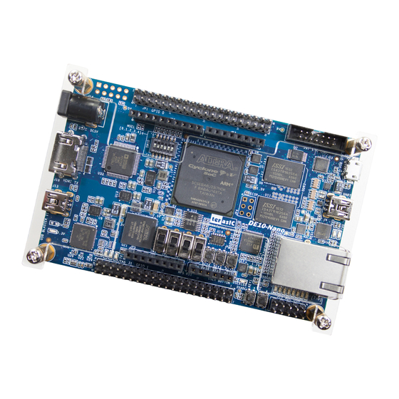
This document illustrates how to setup the Camera demo on the DE10-Nano and the
D8M-GPIO as shown in shown in
In this demonstration, please refer to the DE10-Nano user manual. For details about
the D8M-GPIO, please refer to the user manual of D8M-GPIO daughter card.
2
.
S
y
s
t
e
m
R
e
2
.
S
y
s
t
e
m
R
e
The following items are required to perform this demonstration:
DE10-Nano and power supply
D8M-GPIO
HDMI-Monitor
3
.
E
x
e
c
u
t
e
D
3
.
E
x
e
c
u
t
e
D
Please follow the procedures below to setup the demonstration
1. Make sure both Quartus II and USB-Blaster II driver are installed on the host
PC.
2. Make sure Quartus Prime 16.0 Standard or later is installed on your host PC.
3. Power off the DE10-Nano board
4. Make sure the MSEL[4:0] is set to 10010.
5. Mount the D8M-GPIO onto the 2x20 GPIO_0 expansion header of the DE10-
Nano.
6. Power on the DE10-Nano Board.
7. Execute the demo batch file "test.bat" from the directory
\FPGA\DE10_NANO_D8M_RTL\demo_batch
8. Now, you should see the HDMI monitor
DE10-Nano
D8M RTL
o
n
o
n
Figure
Figure 1 Camera Demo
q
u
i
r
e
m
e
n
t
s
q
u
i
r
e
m
e
n
t
s
e
m
o
n
s
t
r
a
t
i
o
e
m
o
n
s
t
r
a
t
i
o
1
1. The basic design content is also included.
n
n
www.terasic.com
February 24, 2017
Advertisement
Table of Contents

Related Manuals for Terasic DE10-Nano


Summary of Contents for Terasic DE10-Nano
- Page 1 This document illustrates how to setup the Camera demo on the DE10-Nano and the D8M-GPIO as shown in shown in 1. The basic design content is also included. Figure In this demonstration, please refer to the DE10-Nano user manual. For details about the D8M-GPIO, please refer to the user manual of D8M-GPIO daughter card.
- Page 2 VGA_Controller to LCD . In the block, other module (for example, FOCUS_ADJ, MIPI_BRIDGE_CAMERA_Config ) function instructions and KEY/SW operation. All module functions are described below: DE10-Nano www.terasic.com D8M RTL February 24, 2017...
- Page 3 Focus area can be selected by SW3. : There are two options Select focusing the whole screen area (set SW3 to 0) Select focusing the middle area (set SW3 to 1). DE10-Nano www.terasic.com D8M RTL February 24, 2017...
- Page 4 I2C buses. (I2C Slave Address = 0x72), and 1KHz sine wave by I2S bus send to AD7513 output sound. CLOCKMEM: This module will divide MIPI_PIXEL_CLK (25MHz) to 1Hz to display on LEDs DE10-Nano www.terasic.com D8M RTL February 24, 2017...
Need help?
Do you have a question about the DE10-Nano and is the answer not in the manual?
Questions and answers