Table of Contents
Advertisement
Quick Links
S/M No. :
Service Manual
Microwave Oven
Model: KOM-9P25BS
KOM-9P35BS
✔
Caution
: In this Manual, some parts can be changed for improving,
their performance without notice in the parts list. So, if you
need the latest parts information, please refer to PPL(Parts
Price List) in Service Information Center (http://svc.dwe.co.kr).
Dec. 2013
Advertisement
Table of Contents

Related Manuals for Daewoo KOM-9P25BS


Summary of Contents for Daewoo KOM-9P25BS
- Page 1 S/M No. : Service Manual Microwave Oven Model: KOM-9P25BS KOM-9P35BS ✔ Caution : In this Manual, some parts can be changed for improving, their performance without notice in the parts list. So, if you need the latest parts information, please refer to PPL(Parts Price List) in Service Information Center (http://svc.dwe.co.kr).
-
Page 2: Table Of Contents
PRECAUTIONS TO BE OBSERVED BEFORE AND DURING SERVICING TO AVOID POSSIBLE EXPOSURE TO EXCESSIVE MICROWAVE ENERGY (a) Do not operate or allow the oven to be operated with the door open. (b) Make the following safety checks on all ovens to be serviced before activating the magnetron or other micro- wave source, and make repairs as necessary: (1) Interlock operation, (2) Proper door closing, (3) Seal and sealing surfaces (arcing, wear, and other damage), (4) Damage to or loosening of hinges and latches, (5) Evidence of dropping or abuse. -
Page 3: Safety And Precautions
SAFETY AND PRECAUTIONS CAUTION This device is to be Serviced only by Properly Qualified Service Personel. Consult the Service Manual for Proper Service Procedures to Assure Continued Safety Operation and for Precautions to be Taken to Avoid Possible Exposure to Excessive Microwave Energy. 1. -
Page 4: Specifications
SPECIFICATIONS MODEL KOM-9P25BS , KOM-9P35BS POWER SUPPLY 240V AC, 50Hz SINGLE PHASE WITH GROUNDING INPUT POWER 1600 W MICROWAVE ENERGY OUTPUT 1100 W FREQUENCY 2,450MHz OUTSIDE DIMENSIONS (W 542 x 329 x 461 mm CAVITY DIMENSIONS (W 350 x 230 x 357 mm... -
Page 5: External View
EXTERNAL VIEW 1-1 OUTER DIMENSION (KOM-9P25BS) 1-2 OUTER DIMENSION (KOM-9P35BS) -
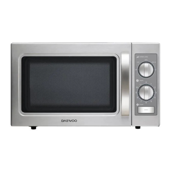
Page 6: Features Diagram
2-1 FEATURES DIAGRAM (KOM-9P25BS) 1 Safety Interlock System. 6 Plate Tray - Made of special heat resistant GLASS. Food in a proper receptacle is placed 2 Door Viewing Screen - Allows viewing of food. on this plate for cooking. The screen is designed so that light can pass 7 Stirrer Cover - This is located on the ceiling through, but not the microwave. - Page 7 2-2 FEATURES DIAGRAM (KOM-9P35BS) 1 Door Hook - When door is closed, it will auto- 7 Knob timer - Used in setting cooking time for matically shut off. If the door is opened while all functions. the oven is operating, magnetron will immedi- 8 START BUTTON- Used to start the microwave ately stop operating.
-
Page 8: Installation
• This appliance is supplied with cable of special type, which, if damaged, must be repaired with cable of same type. Such a cable can be purchased from DAEWOO and must be installed by a qualified person. 6. Examine the oven after unpacking for any damage such as: A misaligned door, broken door or a dent in cavity. -
Page 9: Operations And Functions
OPERATIONS AND FUNCTIONS 1. Connect the mains lead to an electrical outlet. 2. After placing the food in a suitable container, open the oven NOTE door. The plate tray must always be in place during cooking. • Various clicking noises may be heard when 3. -
Page 10: Disassembly And Assembly
DISASSEMBLY AND ASSEMBLY Cautions to be observed when troubleshooting. Unlike many other appliances, the microwave oven is high-voltage, high-current equipment. It is completely safe during normal operation. However, carelessness in servicing the oven can result in an electric shock or possible danger from a short circuit. You are asked to observe the following precautions carefully. - Page 11 1. To remove cabinet 1) Remove four screws on cabinet back. 2) Pull the cabinet backward. 2. To remove door assembly 1) Remove three screws which secure the stopper hinge top. 2) Remove the door assembly from top plate of cavity. 3) Reverse the above for reassembly.
- Page 12 3. To remove door parts. A05-2 A05-3 A05-1 DOOR ASSEMBLY : 3511731000 3511731700 REF NO. PART CODE PART NAME DESCRIPTION Q'TY REMARK 3511731000 KOM-9P2CBS KOM-9P2CBS DOOR AS 3511731700 KOM-9P2CBS KOM-9P35BS 3511714800 KOC-910K0S KOM-9P2CBS DOOR PAINTING AS 3511731110 KOM-9P2C9S KOM-9P35BS 3511714700 DOOR SEAL AS KOC-910K0S KOM-9P2CBS...
- Page 13 4. Method to reduce the gap between the door seal and the oven front surface. (1) To reduce gap located on part ‘A’ • Loosen two screws on the stopper hinge top, and then push the door to contact the door seal to the oven front sur- face.
- Page 14 5-1. To remove control panel parts. (KOM-9P25BS) C/PANEL ASSEMBLY : PKCPSWZZ13 REF No. PART CODE PART NAME DESCRIPTION Q’TY REMARK PKCPSWZZ13 CONTROL-PANEL AS KOM-9P25BS 3516741700 CONTROL-PANEL ABS SG-175, SG-0760D 3511621600 DECORATOR FILM PC T0.5 3511621100 DECORATOR C-PANEL STS430 T0.5 H/L...
- Page 15 5-2. To remove control panel parts. (KOM-9P35BS) C/PANEL ASSEMBLY : 3516742520 REF No. PART CODE PART NAME DESCRIPTION Q’TY REMARK 3516742520 CONTROL-PANEL AS KOM-9P35BS 3513412920 KNOB VPC ABS SG-0760D SG-175 COATING 3511621100 DECORATOR C-PANEL STS430 T0.5 H/L 3511621610 DECORATOR FILM PC T0.5 3516742510 CONTROL-PANEL...
- Page 16 6. To remove guide wind parts. GUIDE WIND ASSEMBLY : 3512524450 REF No. PART CODE PART NAME DESCRIPTION Q’TY REMARK 3512524450 GUIDE WIND AS KOR-1P559S AMANA 3512515300 GUIDE WIND 3963514380 MOTOR SHADED POLE 230V 50Hz OEM-15DWC2-C03 7121403011 SCREW TAPPING T2S PAN 4X30 MFZN 3511800100 P.P GF20 3518605500...
- Page 17 7. To remove high voltage capacitor. 1) Remove the screw which secure the grounding ring terminal of the H.V. diode and the capacitor holder. 2) Remove the H.V. diode from the capacitor holder. 3) Reverse the above steps for reassembly. ◆...
- Page 18 9. To remove wind guide assembly. 1) Remove the screw for earthing. 2) Remove the noise filter from the wind guide. 3) Remove the screw which secure the wind guide assembly. 4) Draw forward the wind guide assembly. 5) Pull the fan from the motor shaft. 6) Remove two screws which secure the motor shaded pole.
-
Page 19: Interlock Mechanism And Adjustment
The door lock mechanism is a device which has been specially designed to completely eliminate microwave radiation when the door is opened during operation, and thus to perfectly prevent the danger resulting from the leakage of microwave. BK (KOM-9P25BS) / BK, GY (KOM-9P35BS) (1) Primary interlock switch When the door is closed, the hook locks the oven door. -
Page 20: Troubleshooting Guide
TROUBLESHOOTING GUIDE Following the procedure below to check if the oven is defective or not. 1. Check grounding before trouble checking. 2. Be careful of the high voltage circuit. 3. Discharge the high voltage capacitor. 4. When checking the continuity of the switches, fuse or high voltage transformer, disconnect one lead wire from these parts and check continuity with the AC plug removed. - Page 21 Does the fan motor work when you shut the door and turn the timer? Does the oven lamp light? Replace or repair oven lamp, Does the turntable turn? turntable motor. Normal reading should be approx. 0 If microwave do not Check continuity No Continuity Continuity...
-
Page 22: Measurement And Test
MEASUREMENT AND TEST 1. MEASUREMENT OF THE MICROWAVE POWER OUTPUT Microwave output power can be checked by indirectly measuring the temperature rise of a certain amount of water exposed to the microwave as directed below. PROCEDURE 1. A cylindrical container of borosilicate glass is used for the test. It has a maximum thickness of 3mm, an external diameter of approximately 190mm and a height of approximately 90mm. -
Page 23: Microwave Radiation Test
2. MICROWAVE RADIATION TEST CAUTION : 1. Make sure to check the microwave leakage before and after repair of adjustment. 2. Always start measuring of an unknown field to assure safety for operating personnel from microwave energy. 3. Do not place your hands into any suspected microwave radiation field unless the safe density level is known. 4. -
Page 24: Component Test Procedure
3. COMPONENT TEST PROCEDURE • High voltage is present at the high voltage terminal of the high voltage transformer during any cooking cycle. • It is neither necessary nor advisable to attempt measurement of the high voltage. • Before touching any oven components or wiring, always unplug the oven from its power source and discharge the capacitor. -
Page 25: Wiring Diagram
WIRING DIAGRAM (KOM-9P25BS) - Page 26 WIRING DIAGRAM (KOM-9P35BS)
-
Page 27: Exploded View And Parts List
EXPLODED VIEW AND PARTS LIST (KOM-9P25BS) 1. DOOR ASSEMBLY Refer to Disassembly and assembly. 2. CONTROL PANEL ASSEMBLY Refer to Disassembly and assembly. 3. GUIDE WIND ASSEMBLY Refer to Disassembly and assembly. 4. TOTAL ASSEMBLY F22 F02 F23 F24... - Page 28 EXPLODED VIEW AND PARTS LIST (KOM-9P35BS) 1. DOOR ASSEMBLY Refer to Disassembly and assembly. 2. CONTROL PANEL ASSEMBLY Refer to Disassembly and assembly. 3. GUIDE WIND ASSEMBLY Refer to Disassembly and assembly. 4. TOTAL ASSEMBLY...
- Page 29 SW MICRO SZM-V16-FA-63 4415A66910 SW MICRO VP-531A-OF/SZM-V16-FA-61 3513601600 LAMP BL 240V 25W T25 C7A H187 3518570400 SWITCH S/A RELAY DWSR-1 (KOM-9P25BS) 7122401211 SCREW TAPPING T2S TRS 4*12 MFZN 7122401211 SCREW TAPPING T2S TRS 4*12 MFZN 3518906510 THERMOSTAT OFF:85 ON:50 H #187...
- Page 30 REF. NO PART CODE PART NAME DESCRIPTION Q'TY 7S312X40A1 SCREW SPECIAL T1 TRS 4X10 SE MFZN 3518121760 TRANS HV R9S59A DS30 3516003700 SPECIAL SCREW TT3 HEX 4X8 FLG MFZN 3518003810 MAGNETRON 2M248H(DW)-B 7S627W50X1 NUT HEX NUT FLANGE M5X0.8P MFZN 3518903900 THERMOSTAT OFF:160 ON:115 H #187 7121300611...
- Page 31 DAEWOO ELECTRONICS CORP. 1-2, Jeo-dong 1(il)-ga, Jung-gu, Seoul, Korea C.P.O. BOX 8003 SEOUL, KOREA TELEX: DWELEC K28177-8 CABLE: “DAEWOOELEC” S/M NO. : PRINTED DATE: Dec. 2013...
- Page 32 ABOUT THIS MANUAL ABOUT THIS MANUAL...
Need help?
Do you have a question about the KOM-9P25BS and is the answer not in the manual?
Questions and answers