Table of Contents
Advertisement
Quick Links
TOWER COMPONENTS REQUIRED
The following tables show a full list of components to build the tower to the platform height specified, complying with the requirements of EN 1004 and Work at Heights
Regulations (WAHR). Braces, platforms, guardrail, bracing frames and toeboards are length specific; 2m, 2.5m or 3m. Three unit weights in ascending order are given for
these items, for 2m, 2.5m and 3m respectively. Other components are common to towers of all lengths, and their unit weights are also given. Total self-weight of towers are
indicated, according to length and height.
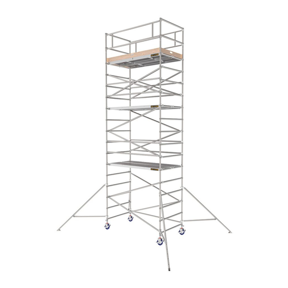
Span 400 Single Width Towers - 2m, 2.5 and 3m lengths to EN1004 and WAHR
Platform Height (m)
Work Height (m)
Tower Height (m)
Tower Weight in Kg (2m length)
Tower Weight in Kg (2.5m length)
Tower Weight in Kg (3m length)
Note: Quoted platform heights included 150mm (6") leg adjustment for levelling that can be increased or reduced
Description
5 Rung Frame
5 Rung Ladder Frame
3 Rung Frame
3 Rung Ladder Frame
Trapdoor Platform
Horizontal Brace
Diagonal Brace
Advance Guardrail
Telescopic Stabiliser (50430)
Large Stabiliser (9090)
Adjustable Legs
Castor / Baseplate
Toe-board set
Span 400 Double Width Towers - 2m, 2.5 and 3m lengths to EN1004 and WAHR
Platform Height (m)
Work Height (m)
Tower Height (m)
Tower Weight in Kg (2m length)
Tower Weight in Kg (2.5m length)
Tower Weight in Kg (3m length)
Note: Quoted platform heights included 150mm (6") leg adjustment for levelling that can be increased or reduced
Description
5 Rung Frame
5 Rung Ladder Frame
3 Rung Frame
3 Rung Ladder Frame
Trapdoor Platform
Fixed Platform
Horizontal Brace
Diagonal Brace
Advance Guardrail
Telescopic Stabiliser (50430)
Large Stabiliser (9090)
Adjustable Legs
Castor / Baseplate
Toe-board set
USAGE ADVICE
• We recommend a minimum of two people to assemble, dismantle and move the
platform tower.
• Check that all components are on site and in good working order.
• Ensure that assembly location is checked to prevent hazards during assembly,
dismantling or moving and while working on the tower. Particular
attention should be given to the ground condition, whether level or sloping,
obstructions and wind
conditions. The ground condition should be capable of supporting the tower
structure.
• Towers must always be climbed from the inside of the assembly and using the
built-in ladder if provided.
• Adjustable legs should only be used to level the tower.
• Lifting operation should be done inside the effective base area of the tower.
• Moving the tower should only be done by manual effect from the base of the
tower. When moving tower be aware of overhead hazards (eg. electric cables).
• No personnel or material should be on the platform whilst the tower is being
moved.
• Beware of horizontal loads which can lead to instability of the tower. The
CARE AND MAINTENANCE OF THE TOWER AND COMPONENTS
• Keep all equipment clean, especially spigots and sockets where frames join. Spigots should fit easily into stocks. Lubricate with light oil.
• Remove dirt or paint from adjustable legs with a light brush, Lightly oil the leg locks.
• Do not strike or hammer components. Do not throw or drop onto hard surfaces.
• Lightly oil spring mechanism of the hooks.
• For transport and storage, components are best stored vertically.
• Damaged parts should be repaired or replaced, contact your supplier.
Unit S1, Friel Avenue, Park West Industrial Park, Nangor Road, Dublin 12, Ireland
2.1
3.4
4.2
5.4
6.3
4
5
6
7
8
3
4
5
6
7
102
144
152
193
201
111
160
167
216
224
118
171
178
232
239
Weight (Kg)
Quantity Required
7.3
1
1
2
2
3
10.6
1
1
2
2
3
4.5
1
2
1
2
1
5.9
1
2
1
2
1
14
18
20
1
2
2
2
2
1.7
2
2.4
1
1
1
1
1
1.8
2.2
2.5
2
4
4
6
6
8.0
2
4
4
6
6
5.2
4
4
4
4
4
6.8
1.1
4
4
4
4
4
2.2
4
4
4
4
4
1
1
1
1
1
1.8
2.2
2.5
2.1
3.4
4.2
5.4
6.3
7.5
8.3
9.6
4
5
6
7
8
9
10
11
3
4
5
6
7
8
9
10
125
183
192
250
259
318
333
391
138
206
215
284
292
361
376
445
149
225
234
310
319
395
410
486
Weight (Kg)
Quantity Required
9.3
1
1
2
2
3
3
4
4
12.6
1
1
2
2
3
3
4
4
5.8
1
2
1
2
1
2
1
2
7.2
1
2
1
2
1
2
1
2
14
18
20
1
2
2
2
2
3
3
3
14
17
20
1
2
2
2
2
3
3
3
1.7
2
2.4
1
1
1
1
1
1
1
1
1.8
2.2
2.5
2
4
4
6
6
8
8
10
8.0
2
4
4
6
6
8
8
10
5.2
4
4
4
4
4
4
6.8
4
4
1.1
4
4
4
4
4
4
4
4
2.2
4
4
4
4
4
4
4
4
1
1
1
1
1
1
1
1
8.7
11.5
14.4
maximum side force is 20kg.
• When tying in the tower, attach a tie to each upright at 4m height intervals. Ensure
that couplers are suitable for 50mm diameter aluminum tube.
• Do not use boxes or steps to gain additional height. If extra height required,
contact your distributor to get extra components.
• Do not lift or suspend assembled mobile tower.
• Components are normally hoisted using a rope. Always lift within the tower
structure or within the base rectangle defined by the stabilisers.
• Damaged components, or components from other tower systems should never be
used.
• Stabilisers should always be fitted when specified. Use the type of stabiliser
shown on the component list according to the tower height.
• When wind exceeds Beaufort force 4, cease using the tower. Wind speeds:
Force
Peak Mph Peak Kph
Guidance
4
18
29
Moderate breeze - raises dust & loose paper
6
31
50
Strong breeze - difficult to use umbrella
8
46
74
Gale force - walking is difficult
Manual is in accordance with EN1298
Tel:
+353 (0) 1 6209300
Fax:
+353 (0) 1 6209301
7.5
8.3
9
10
8
9
249
257
279
286
299
307
3
4
3
4
2
1
2
1
3
3
1
1
8
8
8
8
4
4
4
4
4
4
1
1
10.4
11.6
12.5
12
13
14
11
12
13
400
459
468
453
522
531
495
571
580
5
5
6
5
5
6
1
2
1
1
2
1
3
4
4
3
4
4
1
1
1
10
12
12
10
12
12
4
4
4
4
4
4
4
4
4
1
1
1
Cover Image
Advertisement
Table of Contents

Subscribe to Our Youtube Channel
Related Manuals for Instant Upright Span 400


Summary of Contents for Instant Upright Span 400
- Page 1 2m, 2.5m and 3m respectively. Other components are common to towers of all lengths, and their unit weights are also given. Total self-weight of towers are indicated, according to length and height. Span 400 Single Width Towers - 2m, 2.5 and 3m lengths to EN1004 and WAHR Platform Height (m)
- Page 2 5th rung. Span 400 is a mobile access tower system complying with EN 1004 and WAHR, with vertical ladder access, designed for Class 3 loading. Attach 2 diagonal braces in opposing directions from Attach trapdoor platform and non-trapdoor platform to the 5th the 1st to the 3rd rung.
Need help?
Do you have a question about the Span 400 and is the answer not in the manual?
Questions and answers