Table of Contents
Advertisement
Quick Links
Advertisement
Table of Contents

Related Manuals for Gotharman Tiny LD


Summary of Contents for Gotharman Tiny LD
- Page 1 Gotharman’s Tiny LD Granular Workstation User Manual V13.80...
-
Page 2: Table Of Contents
Very Special Thanks To In The Box Getting Started Connecting MkI Connecting MkII User Interface Preset Select Screen Operating Tiny LD Trigger synth/sampler parts manually Starting/stopping Sequencer Selecting a Part/Track Selecting Effects Processors Note Tracks Steps view/edit Mute/Unmute Note Tracks... - Page 3 Synth/Sampler Parts Modulation Sources Accessing The Synth Part Pages Editing The Parameters Parameters Randomizer Trigger Setup Zone Setup/Microtunings Audio Bus Setup Oscillator/Sampler/Noise Percussion Synthesizer Oscillator Parameters Setting Up (Stereo) Samplings Granular Modulators Random Generators Digital Filters Envelope 1 and 2 LFO 1 to 16 Audio Inputs Setup Analog FilterBoard...
- Page 4 PitchShaper2 Delays Variator Time Stretch Sample Pitch Bass Enhancer (optional) OverShifter Output Effects 1 and 2 List of Output Effects Output Effects Select Page Mix/Pan Modulation and Backwards Delays Granulator SQ Variator Reverb Granulator (unsynced) Xfade Granulator Abstruct0 Time Stretch Sample Pitch...
- Page 5 Sequencer Entering The Sequencer Sequencer Main Clear Sequence Swing All Note subtrack Adjusting The Offset Of All Steps Gate Time subtrack Velocity subtrack Position subtrack Sub Position subtrack Templates and Note Scales Templates for Position subtrack Note Track Mod page Clear Note Track Double Note Track Realtime Recording of Notes...
- Page 6 More… Parameters/Setup Common Settings Morph Setup Common Settings 2 Initialize Preset Parameter Snap Mode FilterBoard Setup VCF8 cutoff limit User Filter FLASH Memory Check Delete Sample Bank Delete All Presets and Songs C.P. Preset/Song Mode Display Update Rate Save Preset Song Mode Accessing Song Mode Song Edit page...
- Page 7 Reload Multiple Files Import Samplings As Chops Make a New Directory Delete File From USB Drive Export Samples, Presets, Songs and User Filter Updating Tiny LD Firmware MIDI Specs Parameters CC Control Parameters CC numbers list Effects parameters 1 and 2...
- Page 8 This product is produced and tested to comply with the low voltage directive (2014/35/EU) and the electromagnetic compatibility directive (2014/30/EU). I hope that you will deform some great tracks...
-
Page 9: Introduction
Introduction Thank you very much for purchasing/consider to purchase a Gotharman’s Tiny LD. Tiny LD are a multi-timbral and polyphonic granular workstation with 16 parts. The granular functions in it includes oscillator/sampler granular modulators and special granular effects. Each of the 16 parts has a stereo oscillator/sampler, 2 filters with 16 different filter types, a stereo VCA, 3 envelopes, 4 random generators and 2 granular modulators, a random one and a sequenced one. - Page 10 All the parameter settings can be stored in any of 1024 rewritable preset locations, and recalled at any time. 1024 song locations are available, for programmed playback of presets, and for tracks mute automation. I hope that you will enjoy your Tiny LD for a long time, and deform a lot of great tracks.
-
Page 11: Very Special Thanks To
Very special thanks to: Dominic Rippel Charles Beullac Jorge Villarroya Traver Bach Pham For supporting this project from the start. I sincerely appreciate your help. -
Page 12: In The Box
In The Box In the Tiny LD box should be: -Tiny LD itself -A power supply –Multi plug –Works in most countries. If any of these items are missing, please get in touch with Gotharman’s. -
Page 13: Getting Started
You would probably like to connect the audio outputs to a mixer or an amplifier, or anything else that ends out in a speaker/a set of speakers. Since Tiny LD doesn’t have built in speakers, it just needs to be connected to something, that can transfer its amazing sound to you. These should be connected, using ¼”... - Page 14 To import a .wav file from another device, it must be: -Mono or stereo -44.1 KHz sample rate – Tiny LD will import other sample rates, but they will play back in a wrong speed -16 bit or 24 bit native PCM...
- Page 15 On the left end panel of your Tiny LD, you will find the stereo audio inputs and MIDI in and out. Connect any line stereo/mono audio sources to the audio inputs, for sampling and/or processing through Tiny LD’s effects and optional analog filter.
-
Page 16: Connecting Mkii
You would probably like to connect the audio outputs to a mixer or an amplifier, or anything else that ends out in a speaker/a set of speakers. Since Tiny LD doesn’t have built in speakers, it just needs to be connected to something, that can transfer its amazing sound to you. These should be connected, using ¼”... - Page 17 Tiny LD to sync to the rest of your setup. On MIDI out, MIDI clock, MIDI CC’s from the Tiny LD edit knobs, and notes and CC’s from its sequencer are transmitted. Connect any MIDI gear to this, that you would like to control from Tiny...
- Page 18 This should be: -Maximum 32 GB -FAT formatted With a USB drive connected, you can: -Import, export and back up samples as .wav files -Import deFormer .lds samples -Import, export and back up Tiny LD/LD3 presets and songs -Update Tiny LD...
- Page 19 To import a .wav file from another device, it must be: -Mono or stereo -44.1 KHz sample rate – Tiny LD will import other sample rates, but they will play back in a wrong speed -16 bit or 24 bit native PCM...
- Page 20 The actual one might look different. Some Tiny LD’s might have been shipped out with a power adaptor, that has multiple tips. If you have received one of these, you should use the tip with the blue ring, and make sure that the 2 parts are alligned to the text “Tip”:...
- Page 22 Turn it on Push the “I” on the power switch. Your Tiny LD should now turn on.
-
Page 23: User Interface
Pushing the Trigger 1-8 buttons, with Func/Mute and 9-16/Part unlit, will trigger the respective Tiny LD part. Each trigger button will send a settable note number (Settable in the Synth “Trig”” section). When a trigger is trigged, the button will light up. - Page 24 With the Func/Mute button lighting up, the functions written just below the steps/parts numbers of the 8 trigger buttons, will ba active. When the Func/Mute button is held down, it is possible to mute/unmute the 16 note tracks, by pushing any of the 8 step buttons. If the 9-16/Part button is lighting up, part 9 to 16 will be muted/unmuted.
- Page 25 The Touch Screen Keyboard The Tiny LD display is touch sensitive. The touch interface is used for navigating through the edit and settings pages, and in the bottom of most pages, a fully playable touch keyboard is present. On the Preset and Song Select pages, it is, besides from playing notes on the touch keyboard, also possible to apply modulation to the sound, by placing your finger on different positions between the top and the bottom of the keyboard.
-
Page 26: Preset Select Screen
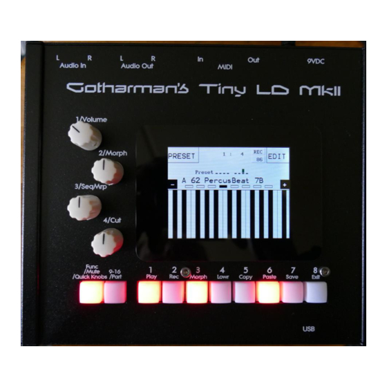
This is the first screen you will see, right after Tiny LD ’s start-up screen, unless you left your Tiny LD in Song mode, the last time it was turned off. Here you can change preset, jump to Tiny LD ’s edit and settings pages, and adjust the touch keyboard settings, as described on the previous pages. - Page 27 Touch “PREV” or “NEXT” to view the previous or next 5 presets, and finally touch the preset name of the preset you would like to select. 1024 presets can be selected, from A01 to P64. Tiny LD will now jump back to the main Preset Select screen, and show the name of the newly selected preset.
- Page 28 When Tiny LD is turned off, it will remember which preset was selected, and start up with this, when turned on again. It will also remember if it was in preset or song mode, and start up in the same mode, and if it was in song mode, it will also remember which song was selected.
- Page 29 If any parameters of the preset has been edited, and the edits has not been stored, a “*” will appear right between the preset number and the preset name. When this appears, you will need to save your preset, in order to keep your edits. Please see how to do this in the “Save Preset”...
-
Page 30: Operating Tiny Ld
Operating Tiny LD Trigger the synth/sampler parts manually To trigger synth/sampler parts 1 to 8 manually, make sure that neither the Func/Mute button or the 9-16/Part button is lighting up, and then push any of the 8 trigger buttons, to trigger the sounds that are programmed on each of these parts. -
Page 31: Starting/Stopping Sequencer
Starting and stopping the Sequencer: To start the sequencer playback, push and release the Func/Mute button, so that it lights up. Then push and release the 1/Play button, so that this lights up too. Now the sequencer is playing back. To stop the sequencer from playing back, make sure that the Func/Mute button is lighting up, and push the 1/Play button, so that this is no longer lighting up. -
Page 32: Selecting A Part/Track
Selecting a part/track: To select a synth/sampler part or a sequencer track for viewing/editing, push and hold the 9- 16/Part button. The selected part number will now be shown, by one of the 8 trigger buttons lightning up, if any of the parts 1 to 8, is already selected. -
Page 33: Note Tracks Steps View/Edit
But more on that later in this manual… Only 8 steps are shown at a time. The note tracks of Tiny LD has 64 steps. On the Sequencer pages, described later in this manual, it is possible to switch which bar should be shown. -
Page 34: Mute/Unmute Note Tracks
Mute/Unmute Note Tracks: To mute, unmute or view the mute state of the 16 note tracks, push and hold the Func/Mute button. If the 9-16/Part button is not lighting up, the state of part 1 to 8 is shown, if it is lighting up, that state of part 9 to 16 is shown. -
Page 35: Copy Morph Layer A To B
5 (Copy), so that this also lights up. Instructions for copy and panic will now be shown on the screen. Push and release step button 8 (Exit). Now all notes, both internally and on any MIDI devices connected to the Tiny LD MIDI out, will be shutted off. -
Page 36: Compare Preset
Compare Edited Preset With Saved Preset When you are editing a preset, and you would like to compare this with the originally saved preset, this is possible, using the Compare function. To listen to the previously saved preset: -Push and release the Func/Mute button, so that it lights up. -Push and release step button 5 (Copy). -
Page 37: Exit From Any Page
Exit from any page You can, at any time, exit from any menu page, using the hardware Exit button. Simply push and release the Func/Mute button, so that it lights up, to enter the function buttons. Now push and release step button 8 (Exit). Exit and Esc (escape) touch buttons are also present on all menu pages, but sometimes a hardware button is just better. -
Page 38: Upper And Lower Parameter Rows
On most edit pages, there are 2 rows of parameters, an upper and a lower. Each row has 4 parameters. Since Tiny LD, unlike LD3, only has 4 edit knob, to edit these parameters, a function that selects the upper and lower row is necessary. -
Page 39: Preset Reload/Song Step Advance
Preset Reload / Advance Song realtime record step Push and release the Func/Mute button, so that it lights up, to enter the function buttons. Now push and hold step button 3 (Morph), while pressing step button 1 (Play), to reload the currently selected preset. -
Page 40: Audio Bus System
Audio Bus System Each of the 16 parts in Tiny LD, consists of a sound generator, that can be selected to be either a multi waveform oscillator, a sampler or a noise generator. The audio signal from the sound generator goes into 2 digital multimode filters. The output signal from the filters goes into a VCA. - Page 42 The Synth/Sampler Parts Tiny LD has 16 parts, that is playing back through 8 stereo voices, using dynamic allocation. Each part must be set up to output to one or two of the 8 audio busses (see the “Audio Bus System”...
- Page 43 List of Modulation Sources: Env1: The output of ADSR Envelope 1 Env1-: The output of ADSR Envelope 1 Inverted Env2: The output of Decay Envelope 2 Env2-: The output of Decay Envelope 2 Inverted Aenv: The output of the VCA Envelope Aenv-: The output of the VCA Envelope Inverted LFO1: The output of LFO1 LFO1-: The output of LFO1 Inverted...
- Page 44 LFO16: The output of LFO16 LFO16-: The output of LFO16 Inverted Rnd1: The output of Part Random Generator 1 Rnd1-: The output of Part Random Generator 1 Inverted Seq1: The output of Sequencer Controller Track 1 Seq1-: The output of Sequencer Controller Track 1 Inverted Seq2: The output of Sequencer Controller Track 2 Seq2-: The output of Sequencer Controller Track 2 Inverted Seq3: The output of Sequencer Controller Track 3...
- Page 45 Seq19: The output of Sequencer Controller Track 19 Seq19-: The output of Sequencer Controller Track 19 Inverted Seq20: The output of Sequencer Controller Track 20 Seq20-: The output of Sequencer Controller Track 20 Inverted Seq21: The output of Sequencer Controller Track 21 Seq21-: The output of Sequencer Controller Track 21 Inverted Seq22: The output of Sequencer Controller Track 22 Seq22-: The output of Sequencer Controller Track 22 Inverted...
- Page 46 CC8: The last MIDI CC 8 value received CC8-: The last MIDI CC 8 value received Inverted CC9: The last MIDI CC 9 value received CC9-: The last MIDI CC 9 value received Inverted TouY: Touch screen keyboard Y-axis position TouY-: Touch screen keyboard Y-axis position Inverted GrRn: Granular Random Modulator GrRn-: Granular Random Modulator Inverted...
- Page 47 CC7: The last MIDI CC 7 value received CC7-: The last MIDI CC 7 value received Inverted Trig: The trigger output of the part Trig-: The trigger output of the part Inverted Rnd2: The output of Part Random Generator 2 Rnd2-: The output of Part Random Generator 2 Inverted Rnd3: The output of Part Random Generator 3 Rnd3-: The output of Part Random Generator 3 Inverted...
- Page 48 CC33: The last MIDI CC 33 value received CC33-: The last MIDI CC 33 value received Inverted CC34: The last MIDI CC 34 value received CC34-: The last MIDI CC 34 value received Inverted CC35: The last MIDI CC 35 value received CC35-: The last MIDI CC 35 value received Inverted CC36: The last MIDI CC 36 value received CC36-: The last MIDI CC 36 value received Inverted...
- Page 49 CC53: The last MIDI CC 53 value received CC53-: The last MIDI CC 53 value received Inverted CC54: The last MIDI CC 54 value received CC54-: The last MIDI CC 54 value received Inverted CC55: The last MIDI CC 55 value received CC55-: The last MIDI CC 55 value received Inverted CC56: The last MIDI CC 56 value received CC56-: The last MIDI CC 56 value received Inverted...
- Page 50 Accessing The Synth Part Pages From the Preset/Song Select screen, Touch the “EDIT” field.
- Page 51 Now Tiny LD will show the main Synth page: In the top of the main Synth page, you will find the 6 main edit groups and the ESC (escape) touch button. Touch any of these group buttons to access them, and touch ESC, to exit to the Preset Select page.
- Page 52 The 4 upper and lower parameters are selected, using the Lowr function, or by touching the corresponding parameter row, as explained under the “Operating Tiny LD” section, earlier in this manual. A green dot in the left side will indicate, which parameter row is selected for editing.
- Page 53 The Synth Part Parameters Randomizer If you should ever need some new inspiration for sounds, or if you just want to surprise yourself with some sounds that you never even imagined, the Tiny LD parameter randomizer might be exactly what you need.
- Page 54 You should now enter this page: Select the part that you would like to randomize, in the same way as you would usually select a part, by pushing and holding the Steps/Part button, while pressing one of the 8 step buttons. Switch the blocks on, that you would like to randomize, simply by touching these, adjust the percentage, that it must maximum change the parameters, using Edit Knob 1, and hit “DO!”.
- Page 55 Synth Part Trigger Setup In this block, you can set up the poly mode of each part, the pitch bend range, the note that will play pack, when pushing a trigger button, and if the part should be an internal or an external part. From the synth parts main page, touch TRIG to enter this page.
- Page 56 MIDI device, and from the part sequencer note track, controls any MIDI device, that is connected to the Tiny LD MIDI output, and that is set to the same MIDI channel, as set by the Chan parameter on this page.
- Page 57 In this block, it is possible to set up a key zone and a MIDI channel for the part, that will take effect, when Tiny LD is set in multi-timbral mode, and is controlled from an external MIDI device. How to set Tiny LD in multi-timbral mode are explained later in this manual, in the MOR>Common section.
- Page 58 Touch Tu1 to enter the first Microtunings page: Here it is possible to microtune each note in an octave by up to +/- 50 percent. This is possible separately for each of the 16 parts, but it is only possible for the Type2 and Resonator oscillators. The Type1 oscillators, the samplers and the noise generators are not affected by these settings.
- Page 59 To set the tunings for the keys G# to B, touch Tu2, to go to the next tuning page:...
- Page 60 Audio BUS Setup In this block, you will find the settings for the 8 audio busses. Please note that these settings are not part specific, but global for the 8 busses and 16 parts. From the synth parts main page, touch TRIG to enter this page. Touch the Out touch button, to enter this first page, where you can select the output, which the audio signal from each of the 8 busses, should be sent to.
- Page 61 Touch the Rel touch button, to enter this second audio Bus page, where it is possible to adjust the release time of the envelope follower, that are attached to each audio Bus, and that affects the output levels of these. When this is set to 511, the follower will never decay.
- Page 62 Touch the Gan touch button, to enter this third audio Bus page, where it is possible to gain or attenuate the level of the audio signal sent to the Bus envelope follower. At +0, there are no gaining or attenuation. At positive values the signal to the follower is gained, at negative values, they are attenuated.
- Page 63 Touch the Lvl touch button, to enter this fourth audio Bus page, where it is possible to adjust the total output level of each Bus. Positive values will gain the output signal, negative values will attenuate.
- Page 64 Touch the Env touch button, to enter this fifth and last audio Bus page, where it is possible to assign any of the 16 part VCA envelopes or the BUS Envelope Follower to control the Bus output level. Here it is also possible to gain the Envelope Follower by x2 and x4. As default, the un-gained Envelope Follower are assigned to control the BUS output level.
- Page 65 A Tiny LD oscillator can be set to act as an oscillator, a sample player, a chopped keyboard sample player, or a noise generator.
- Page 66 In off and on (unchopped) modes, the whole sampling will play back, ignoring any chop points. It is possible to create chop points in the Tiny LD sample editor, and use these. Chops can be detected by level peaks, by single wavecycles, and by dividing the sample length with a settable number.
- Page 67 In trial mode it is possible to import the preset set made for the Percussion Synthesizer, but you must import all presets from a folder, in order to get them stored in the LD3/Tiny LD preset memory. If you import them one preset at a time, it is not possible to save these presets.
- Page 68 The 6 Percussion Oscillator types: Perc: Percussion oscillator 1. This outputs 2 percussion waves, that can be detuned from each other, and noise FM can be applied. Atk will morph between the attack and the body of the percussion sound. To imitate the strike of the drum, modulate Atk with an envelope. Noise PW can also be set, to adjust the intensity of the FM noise.
- Page 69 Sound ideas / Start points You can, of course, use the percussion synthesizer presets as starting points, and copy/paste sounds from these to a new preset. But if you would like to start from scratch, or you just want to get an idea of, how specific sounds can be generated, here are some ideas.
- Page 70 Select the Prc3 oscillator type. Set Dtun, Atk and Noiz all to zero. Set pitch modulation to Env1, to 42, and set Atk modulation to Env1, to 305. If you are triggering the sound from the trigger buttons, set Tune to -8. Set Env1 A to 0, D to 52, S to 0 and R to 118. Set the VCA Env A to 0, D to 84, S to 408 and R to 66.
- Page 71 Analog style open Hi hat Copy and paste the analog style closed hi hat to another part. Set the VCA Env A to 0, D to 22, S to 415 and R to 208. Now you got an open version of the closed hi hat! Cymbal Select the Cymb oscillator type.
- Page 72 Bell sound Select the Perc oscillator type. Set Dtun to 169, Atk to 120 and Noiz to 0. If you are triggering the sound from the trigger buttons, set Tune to +0. Set Atk modulation to Env1, and set this to 254. Set VCA Env A to 0, D to 22, S to 511, R to 191.
- Page 73 PW: Adjusts the pulse width of the waveform. Unlike many other oscillator designs, the pulse width can be adjusted on all of Tiny LD’s waveforms, not just the pulse wave. FM: FM amount. The more this is turned up, the more a selected audio bus (in the SEL section) will...
- Page 74 Great for lowpass filtered and natural sounding sounds. Reso: Resonator oscillator. An oscillator that is partly generated by a special Gotharman engineered filter, that has multiple resonances in its feedback path. Great for emulating string instruments, and for new synthetic sounds.
- Page 75 The OSC page, when Perc, Prc2 or Prc3 is selected as type: In the upper left corner of the oscillator page, the currently generated waveform is shown. Touch the buttons named OSC, MOD, SEL, SMP and Mod2, to enter other oscillator pages, like Modulation and oscillator/sampler/noise mode select.
- Page 76 Great for lowpass filtered and natural sounding sounds. Reso: Resonator oscillator. An oscillator that is partly generated by a special Gotharman engineered filter, that has multiple resonances in its feedback path. Great for emulating string instruments, and for new synthetic sounds.
- Page 77 The OSC page, when Cymb or Cym2 is selected as type: In the upper left corner of the oscillator page, the currently generated waveform is shown. Touch the buttons named OSC, MOD, SEL, SMP and Mod2, to enter other oscillator pages, like Modulation and oscillator/sampler/noise mode select.
- Page 78 Great for lowpass filtered and natural sounding sounds. Reso: Resonator oscillator. An oscillator that is partly generated by a special Gotharman engineered filter, that has multiple resonances in its feedback path. Great for emulating string instruments, and for new synthetic sounds.
- Page 79 The OSC page, when Clap is selected as type: In the upper left corner of the oscillator page, the currently generated waveform is shown. Touch the buttons named OSC, MOD, SEL, SMP and Mod2, to enter other oscillator pages, like Modulation and oscillator/sampler/noise mode select.
- Page 80 Great for lowpass filtered and natural sounding sounds. Reso: Resonator oscillator. An oscillator that is partly generated by a special Gotharman engineered filter, that has multiple resonances in its feedback path. Great for emulating string instruments, and for new synthetic sounds.
- Page 81 The OSC page, when in Sampler, Chopped Keyboard mode and Xfade mode: In the bottom of the sampler page, the selected samplings waveform is shown in rough graphics. When the sample, or part of it, is played back, the small black line below the waveform will show the current playback point.
- Page 82 Loop: Sets the sampling loop mode. Off: The sample will not loop, just play back one time from the adjusted, or chop selected, start to end, and then stop. If the selected sampling has chop points, these will always be used. On: The sample will play back from the adjusted start point, when triggered.
- Page 83 Oscillator modulation The MOD page, when in oscillator mode: The small VU-meters next to the parameters, shows the activity of the selected modulation sources. For each parameter, that can be modulated, it is possible to select a modulation source, and to adjust the modulation amount.
- Page 84 The MOD page, when Perc, Prc2 or Prc3 is selected as Type: The small VU-meters next to the parameters, shows the activity of the selected modulation sources. For each parameter, that can be modulated, it is possible to select a modulation source, and to adjust the modulation amount.
- Page 85 The MOD page, when Cymb or Cym2 is selected as Type: The small VU-meters next to the parameters, shows the activity of the selected modulation sources. For each parameter, that can be modulated, it is possible to select a modulation source, and to adjust the modulation amount.
- Page 86 The MOD page, when Clap is selected as Type: The small VU-meters next to the parameters, shows the activity of the selected modulation sources. For each parameter, that can be modulated, it is possible to select a modulation source, and to adjust the modulation amount.
- Page 87 The MOD page, when in sampler or chopped keyboard mode: The small VU-meters next to the parameters, shows the activity of the selected modulation sources. For each parameter, that can be modulated, it is possible to select a modulation source, and to adjust the modulation amount.
- Page 88 The MOD page, when in sampler Xfade mode: The small VU-meters next to the parameters, shows the activity of the selected modulation sources. For each parameter, that can be modulated, it is possible to select a modulation source, and to adjust the modulation amount.
- Page 89 Oscillator/Sampler/Chopped Keyboard/Noise mode select Touch the SEL button, to enter this page. The mode select page, when in oscillator, sampler or chopped keyboard mode: Xfade: Sample fade mode. Only affects sample playback. Off: No fading are applied to sample playback. On: When playing back a sampling, both fade in and fade out will be applied.
- Page 90 #Smp: Number of samplings. Sets if the part should use 1, 2 or 4 samplings. The 4 samplings are selected on the SMP page, and the samplings can be selected, using the Chop parameter on the sampler OSC page. TrgTo: Off, 1 to 16. Makes this part trigger another part. If set to this part, the part will double trigger.
- Page 91 Xfade: Sample crossfade position. By turning this parameter from the lowest to the highest position, Tiny LD will crossfade from the sampling selected by the Chop parameter, to the sampling selected by the Chop2 parameter. This parameter can be morphed and modulated.
- Page 92 TrDly: 0 to 511. Trigger delay. Will add a delay, before it triggers the other part, if set to any other values than zero. TrLen: 0 to 511. Trigger length. Sets how long the extra trigger gate should be. If set to zero, it might not trigger.
- Page 93 Part Samples Select Touch the SMP button, to enter this page. Here you can select 4 samplings for the part. The number of these samplings, that are used, is set by the #Smp parameter on the SEL page. The 4 samples can be selected to play back, setting the Chop parameter, and by chop select modulation.
- Page 94 To select a sampling for any of the 4 slots, simply touch the sample name. Now this page will pop On each page you will view 16 of the samplings, that are held in the Tiny LD FLASH memory. Touch PREV and NEXT to view the previous or next 16 samplings.
- Page 95 Oscillator Modulation 2 The Mod2 page, when in oscillator mode: The small VU-meters next to the parameters, shows the activity of the selected modulation sources. For each parameter, that can be modulated, it is possible to select a modulation source, and to adjust the modulation amount.
- Page 96 The Mod2 page, when Perc, Prc2 or Prc3 is selected as Type: The small VU-meters next to the parameters, shows the activity of the selected modulation sources. For each parameter, that can be modulated, it is possible to select a modulation source, and to adjust the modulation amount.
- Page 97 The Mod2 page, when Cymb or Cym2 is selected as Type: The small VU-meters next to the parameters, shows the activity of the selected modulation sources. For each parameter, that can be modulated, it is possible to select a modulation source, and to adjust the modulation amount.
- Page 98 The Mod2 page, when Clap is selected as Type: The small VU-meters next to the parameters, shows the activity of the selected modulation sources. For each parameter, that can be modulated, it is possible to select a modulation source, and to adjust the modulation amount.
- Page 99 The Mod2 page, when in sampler or chopped keyboard mode: The small VU-meters next to the parameters, shows the activity of the selected modulation sources. For each parameter, that can be modulated, it is possible to select a modulation source, and to adjust the modulation amount.
- Page 100 Mode: New/Old sample rate. When set to “New”, samples will play back at 44.100 Hz, when set to “Old”, samples will play back at 43.945 Hz. To ensure compatibility with samples recorded before firmware version 13.34, in which a sample clock deviation were corrected.
- Page 101 How to set up (stereo) samplings In this chapter it will be explained, how to set up a sampling for a part, and some extra steps, that is required for setting the filters and VCA/BUS in stereo mode, when setting up a stereo sampling. From the Preset Select page, touch “EDIT”...
- Page 102 From the Synth main page, touch the box named “OSC”, to enter the oscillator pages.
- Page 103 Touch the “SEL” touch button, to enter the oscillator mode selection page.
- Page 104 Set the “Mode” parameter to “Smp”. Now touch the “SMP” touch button, to enter the sample selection page.
- Page 105 Here you can select up to 4 samplings for the part. The number of these samplings, that are used, is set by the #Smp parameter on the SEL page. The 4 samples can be selected to play back, setting the Chop parameter, and by chop select modulation. For now, just touch the sample name, that starts with “1:”, to open the sample select page for the first sampling.
- Page 106 MIDI device, and from the sequencer. If a stereo sampling is selected, a few extra steps are required, to get Tiny LD to output both audio channels from this. These steps will be explained on the following pages.
- Page 107 Extra steps required, for setting up a stereo sampling The extra steps required for setting up a stereo sampling are: -Set up the VCA to output to 2 audio busses. -Set up these audio busses to output to left and right. -Set the filters in stereo mode.
- Page 108 Set the “Bus” parameter, so that the VCA will output to 2 busses – “1+2”, “3+4”, “5+6” or “7+8”. Now touch the “MOD” touch button.
- Page 109 Make sure that “Pan” is set to “Man”, and pan “Amt” to “256”. Exit the VCA pages, to go back to the Synth main page.
- Page 110 Touch the box named “BUS”, to enter the audio bus pages.
- Page 111 On this first Bus page, set the audio busses, that the VCA is outputting to, to respectively L and R, like Bus 5 and 6 on the picture. Exit from this page, to the Synth main page.
- Page 112 Touch the box named “FLT”, to enter the digital filter pages.
- Page 113 Make sure that the selected Type is NOT SvfL, SvfB, SvfH or SvfN. These 4 filter types are mono only filters. Touch the “SET” touch button.
- Page 114 On this page, set the “Stereo” parameter to “On”. It does not matter, if the digital filters are used or not, this routing has to be set to stereo, in order to get both audio channels of a stereo sampling through. Now when you trigger the selected stereo sampling, it should play back in stereo!
- Page 115 The Granular Modulators Each of the 16 synth parts of Tiny LD has 2 granular modulators, the granular random generator and the granular sequence modulator, that shows as modulation sources, to any parameter that can be modulated. GrRn – Granular Random Generator This works in conjunction with the part oscillator, sampler or noise generator.
- Page 116 When in sampler mode: Every time the sampler loops, the granular sequence modulator gets the next value from the associated controller track. If you have a wave chopped sampling, and set this parameter up to modulate the chop select parameter, it is possible to program wave sequences. Of course, this can also modulate any other parameter, for infinite possibilities.
- Page 117 4 Random Generators Each synth part of Tiny LD has 4 random generators, that takes in a new random value, every time the part is trigged. There are no settings to be made for these. They are found as modulation sources, named: Rnd1,...
- Page 118 The Digital Filters Each Tiny LD part has 2 digital filters. For each of these, 20 different filter types can be selected. They have various lowpass, highpass and bandpass modes, with different characteristics, but also special modes like Lo-Fi, destruktion and Fat. They can be connected in serial or parallel to each other, work as one stereo filter, and their parameters can be linked to each other, for easier tweaking in stereo mode.
- Page 119 List of Digital Filter Types: LPF1: Lowpass filter with a rather weak character. Resonance does not self-oscillate. LPF2: Lowpass filter that are a bit sharper than LPF1. Resonance does not self-oscillate. LPF3: Sharp Lowpass filter with self-oscillating resonance. LPF4: Very sharp Lowpass filter with self-oscillating resonance. BPF1: Bandpass filter with a rather weak character.
- Page 120 Digital Filters Parameters From the synth parts main page, touch FLT to enter the digital filters. Touch the FL1 touch button, to enter the Filter 1 page. Cut: 0 to 511. Sets the cutoff frequency of the filter. Reso: 0 to 511. Sets the amount of resonance applied to the filter. Inp: 0 to 511.
- Page 121 Low: 0 to 511. Sets the lowest frequency offset point of the filter. Turning this up, will in many filter types, make the bass bottom more present or distorted. This has no function, when an Svf type filter is selected. Boost: 0 to 511.
- Page 122 Filter 1 Modulation Touch the MO1 touch button, to enter the Filter 1 Modulation page. The small VU-meters next to the parameters, shows the activity of the selected modulation sources. For each parameter, that can be modulated, it is possible to select a modulation source, and to adjust the modulation amount.
- Page 123 Filter 2 (Not available when Osc is in Xfade mode or when Flt1= Svf type ) Touch the FL2 touch button, to enter the Filter 2 page. Cut: 0 to 511. Sets the cutoff frequency of the filter. Reso: 0 to 511. Sets the amount of resonance applied to the filter. Inp: 0 to 511.
- Page 124 Low: 0 to 511. Sets the lowest frequency offset point of the filter. Turning this up, will in many filter types, make the bass bottom more present or distorted. Boost: 0 to 511. Gains the filter output level.
- Page 125 Filter 2 Modulation (Not available when Osc is in Xfade mode or when Flt1= Svf type ) Touch the MO2 touch button, to enter the Filter 2 Modulation page. The small VU-meters next to the parameters, shows the activity of the selected modulation sources.
- Page 126 Filters Setup (Not available when Osc is in Xfade mode –Filter1 is always stereo, and not available when Flt1= Svf type ) Touch the SET touch button, to enter the Filters Setup page. Stereo: Off, On. When off, the left and the right audio signals, coming from the oscillators (only really effective, when stereo samplings are played back), are mixed to one mono signal, that goes through both filters.
- Page 127 The VCA is the last stage of a synth part, before the audio is sent to the Audio Bus system. The audio output from the digital filter, goes into the VCA. The VCA’s can behave in 4 different modes. Linear, logarithmic, smooth linear and smooth logarithmic.
- Page 128 VCA Parameters From the synth parts main page, touch VCA to enter the VCA pages. Touch the VCA touch button, to enter the VCA parameters page. The VU-meter at the right of the screen, shows the VCA output activity. A: 0 to 511. VCA envelope attack time. The time it will take the VCA envelope to rise from zero to its maximum value, when a note event is received and held down.
- Page 129 Bus: 1/2 , 3/4 , 5/6 , 7/8 , 1, 2, 3, 4, 5, 6, 7, 8. Selects to which Audio Bus(ses) the VCA should output its audio to. When 2 busses are selected, the pan parameter and modulation, pans the audio signal between the 2 busses.
- Page 130 VCA Modulation Touch the MOD touch button, to enter the VCA modulation page. The VU-meter at the right of the screen, shows the VCA output activity. The small VU-meters next to the parameters, shows the activity of the selected modulation sources. For each parameter, that can be modulated, it is possible to select a modulation source, and to adjust the modulation amount.
- Page 131 Envelope 1 and 2 Each Synth part of Tiny LD has 2 modulation envelopes. One ADSR type, and one decay only envelope. Envelope 1, the ADSR envelope can have linear or logarithmic characteristics, it is possible to loop the ADS segment, and it also has an offset control.
- Page 132 Envelope 1 and 2 Parameters From the synth parts main page, touch ENV to enter the envelope pages. Touch the ENV touch button, to enter the envelope parameters page. The VU-meter at the right of the screen, shows the Envelope output. A: 0 to 511.
- Page 133 -Off: The envelope will work around the zero point, and apply both negative and positive modulation to the parameters affected by it. -On: Positive only, offset added. The envelope will only work above the zero point, and will only add to the values of the parameters affected by it. Mode: Selects if the envelope curve should be linear (Lin), or logarithmic (Log).
- Page 134 Envelope Modulation Touch the MOD touch button, to enter the envelope modulation page. The VU-meter at the right of the screen, shows the Envelope output. The small VU-meters next to the parameters, shows the activity of the selected modulation sources. For each parameter, that can be modulated, it is possible to select a modulation source, and to adjust the modulation amount.
- Page 135 LFO1 to 16 Tiny LD has 16 LFO’s, that are global, so each LFO can modulate any of the 16 Synth parts. The LFO's has continuously variable waveform, curve and rate parameters. All of these parameters can be modulated. The output level of the LFO’s can also be modulated, and they can be key- synced.
- Page 136 LFO parameters From the synth part main page, touch the LFO block, to enter the LFO pages. Touch the LFO touch button, to select this page. At the right of this page, the current LFO waveform is shown, together with a small VU-meter, showing the LFO output activity.
- Page 137 KeyS: Off, 1 to 16, 1s to 16s: LFO key sync. The number tells which part will make the LFO restart. When a number that has an “s” after it is selected, the LFO are in single cycle mode, and will only run one cycle, every time it is triggered.
- Page 138 Touch the MOD touch button, to select this page. The VU-meter at the right of the screen, shows the LFO activity. The small VU-meters next to the parameters, shows the activity of the selected modulation sources. For each parameter, that can be modulated, it is possible to select a modulation source, and to adjust the modulation amount.
- Page 139 Audio Inputs Setup Each audio input on Tiny LD, can input to an audio bus. The setup of this, is done in this section. From the synth parts main page, touch INP, to enter this page: InpL, InpR: Off, 1 to 8. Sets the audio bus, that the corresponding audio input is sent to. When set...
- Page 140 To make sure that the parameters on the pages fits the installed filterboard, some filters needs to be configured. This is done in the “MOR” section. If you ordered your Tiny LD together with the analog filterboard, this has already been configured.
- Page 141 From the synth parts main page, touch MOR on the top navigation bar. On the MOR page, touch VCF TYPES, to enter this page: Here you can, by adjusting edit knob 1, set up which filterboard are installed in the filterboard slot. This can be set to: 1-Single Filter 2-Dual Filter...
- Page 142 Analog Filterboard Parameters From the synth parts main page, touch the VCFs block, to enter the analog filter pages. The Single Filter parameters: Touch the VCF touch button, to enter this page. The VU-meter at the right of the screen, shows the filter output activity. Cut: 0 to 511.
- Page 143 Touch the RAY touch button, to enter this page. The VU-meter at the right of the screen, shows the filter output activity. G-Ray: Adjusts the amount of g-RAY intermodulation. 0: no g-RAY, 3: max g-RAY. Range: 0 to 3. Mode: G-Ray mode. -Norm: Normal 1:1 feedback.
- Page 144 Feed: Selects the function of the Feed parameter: -Sepa: The value of the Feed parameter is a totally separate value, and is not affected by the Cutoff value. -Add: The value of the Feed parameter is added to the Cutoff value. -Sub: The value of the Feed parameter is subbed from the Cutoff value.
- Page 145 Touch the MO1 touch button, to enter this page. The VU-meter at the right of the screen, shows the filter output activity. For each parameter, that can be modulated, it is possible to select a modulation source, and to adjust the modulation amount. Only the positive modulation sources, can be selected by the Edit Knobs.
- Page 146 Touch the MO2 touch button, to enter this page. The VU-meter at the right of the screen, shows the filter output activity. For each parameter, that can be modulated, it is possible to select a modulation source, and to adjust the modulation amount. Only the positive modulation sources, can be selected by the Edit Knobs.
- Page 147 Touch the Mix touch button, to enter this page. The VU-meter at the right of the screen, shows the filter output activity. Bus: 1 to 8. The audio Bus, that the filter will be placed on. Inp: 0 to 511. The audio input level for the filters. Outp: -128 to +383.
- Page 148 The Dual Filter parameters: Touch the VCF touch button, to enter this page. The VU-meter at the right of the screen, shows the filter output activity. Cut: 0 to 511. Adjusts the filter cutoff frequency for filter one, a bandpass filter. Peaks: 0 to 511.
- Page 149 Touch the RAY touch button, to enter this page. The VU-meter at the right of the screen, shows the filter output activity. G-Ray: Adjusts the amount of g-RAY intermodulation. 0: no g-RAY, 3: max g-RAY. Range: 0 to 3. Mode: G-Ray mode. -Norm: Normal 1:1 feedback.
- Page 150 Feed: Selects the function of the Feed parameter: -Sepa: The value of the Feed parameter is a totally separate value, and is not affected by the Cutoff value. -Add: The value of the Feed parameter is added to the Cutoff value. -Sub: The value of the Feed parameter is subbed from the Cutoff value.
- Page 151 Touch the MO1 touch button, to enter this page. The VU-meter at the right of the screen, shows the filter output activity. For each parameter, that can be modulated, it is possible to select a modulation source, and to adjust the modulation amount. Only the positive modulation sources, can be selected by the Edit Knobs.
- Page 152 Touch the MO2 touch button, to enter this page. The VU-meter at the right of the screen, shows the filter output activity. For each parameter, that can be modulated, it is possible to select a modulation source, and to adjust the modulation amount. Only the positive modulation sources, can be selected by the Edit Knobs.
- Page 153 Touch the Mix touch button, to enter this page. The VU-meter at the right of the screen, shows the filter output activity. Bus: 1 to 8. The audio Bus, that the filter will be placed on. Inp: 0 to 511. The audio input level for the filters. Outp: -128 to +383.
- Page 154 The Trippple Filter parameters: Touch the VCF touch button, to enter this page. The VU-meter at the right of the screen, shows the filter output activity. Cut: 0 to 511. Adjusts the filter cutoff frequency for filter1, the LPF. BpCut: 0 to 511. Adjusts the filter cutoff for filter 2, the BPF. Reso: Adjusts the resonance of all the filters.
- Page 155 Touch the RAY touch button, to enter this page. The VU-meter at the right of the screen, shows the filter output activity. G-Ray: Adjusts the amount of g-RAY intermodulation. 0: no g-RAY, 3: max g-RAY. Range: 0 to 3. Mode: G-Ray mode. -Norm: Normal 1:1 feedback.
- Page 156 HpCut: Selects the function of the Feed parameter: -Sepa: The value of the HpCut parameter is a totally separate value, and is not affected by the Cutoff value. -Add: The value of the HpCut parameter is added to the Cutoff value. -Sub: The value of the HpCut parameter is subbed from the Cutoff value.
- Page 157 Touch the MO1 touch button, to enter this page. The VU-meter at the right of the screen, shows the filter output activity. For each parameter, that can be modulated, it is possible to select a modulation source, and to adjust the modulation amount. Only the positive modulation sources, can be selected by the Edit Knobs.
- Page 158 Touch the MO2 touch button, to enter this page. The VU-meter at the right of the screen, shows the filter output activity. For each parameter, that can be modulated, it is possible to select a modulation source, and to adjust the modulation amount. Only the positive modulation sources, can be selected by the Edit Knobs.
- Page 159 Touch the Mix touch button, to enter this page. The VU-meter at the right of the screen, shows the filter output activity. Bus: 1 to 8. The audio Bus, that the filter will be placed on. Inp: 0 to 511. The audio input level for the filters. Outp: -128 to +383.
- Page 160 Gman’s First Filter parameters: Touch the VCF touch button, to enter this page. The VU-meter at the right of the screen, shows the filter output activity. Cut: 0 to 511. Adjusts the filter cutoff frequency. Peaks: 0 to 511. Adjusts the filter cutoff for the second filter block. Reso: Adjusts the resonance of the filter.
- Page 161 Touch the RAY touch button, to enter this page. The VU-meter at the right of the screen, shows the filter output activity. G-Ray: Adjusts the amount of g-RAY intermodulation. 0: no g-RAY, 3: max g-RAY. Range: 0 to 3. Mode: G-Ray mode. -Norm: Normal 1:1 feedback.
- Page 162 Feed: Selects the function of the Feed parameter: -Sepa: The value of the Feed parameter is a totally separate value, and is not affected by the Cutoff value. -Add: The value of the Feed parameter is added to the Cutoff value. -Sub: The value of the Feed parameter is subbed from the Cutoff value.
- Page 163 Touch the MO1 touch button, to enter this page. The VU-meter at the right of the screen, shows the filter output activity. For each parameter, that can be modulated, it is possible to select a modulation source, and to adjust the modulation amount. Only the positive modulation sources, can be selected by the Edit Knobs.
- Page 164 Touch the MO2 touch button, to enter this page. The VU-meter at the right of the screen, shows the filter output activity. For each parameter, that can be modulated, it is possible to select a modulation source, and to adjust the modulation amount. Only the positive modulation sources, can be selected by the Edit Knobs.
- Page 165 Touch the Mix touch button, to enter this page. The VU-meter at the right of the screen, shows the filter output activity. Bus: 1 to 8. The audio Bus, that the filter will be placed on. Inp: 0 to 511. The audio input level for the filters. Outp: -128 to +383.
- Page 166 The MiniProphet Filter parameters: Touch the VCF touch button, to enter this page. The VU-meter at the right of the screen, shows the filter output activity. Cut: 0 to 511. Adjust the filter cutoff frequency. Reso: 0 to 511. Adjusts the resonance of the filter. LPF1: Switches filter output 1 between 24dB and 12dB steepness.
- Page 167 Touch the RAY touch button, to enter this page. The VU-meter at the right of the screen, shows the filter output activity. G-Ray: Adjusts the amount of g-RAY intermodulation. 0: no g-RAY, 3: max g-RAY. Range: 0 to 3. Mode: G-Ray mode. -Norm: Normal 1:1 feedback.
- Page 168 FM: 0 to 511. The amount of frequency modulation (audio range), that are applied to all of the filter cutoff frequencies, from the audio Bus selected by the FmBus parameter.
- Page 169 Touch the MO1 touch button, to enter this page. The VU-meter at the right of the screen, shows the filter output activity. For each parameter, that can be modulated, it is possible to select a modulation source, and to adjust the modulation amount. Only the positive modulation sources, can be selected by the Edit Knobs.
- Page 170 Touch the MO2 touch button, to enter this page. The VU-meter at the right of the screen, shows the filter output activity. For each parameter, that can be modulated, it is possible to select a modulation source, and to adjust the modulation amount. Only the positive modulation sources, can be selected by the Edit Knobs.
- Page 171 Touch the Mix touch button, to enter this page. The VU-meter at the right of the screen, shows the filter output activity. Bus: 1 to 8. The audio Bus, that the filter will be placed on. Inp: 0 to 511. The audio input level for the filters. Outp: -128 to +383.
- Page 172 The SP Filter parameters: Touch the VCF touch button, to enter this page. The VU-meter at the right of the screen, shows the filter output activity. Cut: 0 to 511. Adjust the filter cutoff frequency. Reso: 0 to 511. Adjusts the resonance of the filter. Rate: Sample Rate.
- Page 173 Touch the RAY touch button, to enter this page. The VU-meter at the right of the screen, shows the filter output activity. G-Ray: Adjusts the amount of g-RAY intermodulation. 0: no g-RAY, 3: max g-RAY. Range: 0 to 3. Mode: G-Ray mode. -Norm: Normal 1:1 feedback.
- Page 174 Fuzz: Selects whether output 2 (Fuzz) of the analog filter should be normal (Nrm) or inverted (Inv). Sometimes it can get some great effects, when inverting output 2 of the filter, and adjust the Out1/2 mix. FM: 0 to 511. The amount of frequency modulation (audio range), that are applied to all of the filter cutoff frequencies, from the audio Bus selected by the FmBus parameter.
- Page 175 Touch the MO1 touch button, to enter this page. The VU-meter at the right of the screen, shows the filter output activity. For each parameter, that can be modulated, it is possible to select a modulation source, and to adjust the modulation amount. Only the positive modulation sources, can be selected by the Edit Knobs.
- Page 176 Touch the MO2 touch button, to enter this page. The VU-meter at the right of the screen, shows the filter output activity. For each parameter, that can be modulated, it is possible to select a modulation source, and to adjust the modulation amount. Only the positive modulation sources, can be selected by the Edit Knobs.
- Page 177 Touch the Mix touch button, to enter this page. The VU-meter at the right of the screen, shows the filter output activity. Bus: 1 to 8. The audio Bus, that the filter will be placed on. Inp: 0 to 511. The audio input level for the filters. Outp: -128 to +383.
- Page 178 The Tubaz Filter parameters: Touch the VCF touch button, to enter this page. The VU-meter at the right of the screen, shows the filter output activity. Cut: 0 to 511. Adjust the filter cutoff frequency. Reso: 0 to 511. Adjusts the resonance of the filter. Feed: -256 to +255.
- Page 179 Touch the RAY touch button, to enter this page. The VU-meter at the right of the screen, shows the filter output activity. G-Ray: Adjusts the amount of g-RAY intermodulation. 0: no g-RAY, 3: max g-RAY. Range: 0 to 3. Mode: G-Ray mode. -Norm: Normal 1:1 feedback.
- Page 180 Out2: Selects whether output 2 of the analog filter should be normal (Nrm) or inverted (Inv). Sometimes it can get some great effects, when inverting output 2 of the filter, and adjust the Out1/2 mix. FM: 0 to 511. The amount of frequency modulation (audio range), that are applied to all of the filter cutoff frequencies, from the audio Bus selected by the FmBus parameter.
- Page 181 Touch the MO1 touch button, to enter this page. The VU-meter at the right of the screen, shows the filter output activity. For each parameter, that can be modulated, it is possible to select a modulation source, and to adjust the modulation amount. Only the positive modulation sources, can be selected by the Edit Knobs.
- Page 182 Touch the MO2 touch button, to enter this page. The VU-meter at the right of the screen, shows the filter output activity. For each parameter, that can be modulated, it is possible to select a modulation source, and to adjust the modulation amount. Only the positive modulation sources, can be selected by the Edit Knobs.
- Page 183 Touch the Mix touch button, to enter this page. The VU-meter at the right of the screen, shows the filter output activity. Bus: 1 to 8. The audio Bus, that the filter will be placed on. Inp: 0 to 511. The audio input level for the filters. Outp: -128 to +383.
- Page 184 The Dual Band SSI Filter parameters: Touch the VCF touch button, to enter this page. The VU-meter at the right of the screen, shows the filter output activity. HpCut: HPF/LPF 1 and 2 filter cutoff frequency. Space between the 2 filters can be adjusted with Space.
- Page 185 Touch the RAY touch button, to enter this page. The VU-meter at the right of the screen, shows the filter output activity. G-Ray: Adjusts the amount of g-RAY intermodulation. 0: no g-RAY, 3: max g-RAY. Range: 0 to 3. Mode: G-Ray mode. -Norm: Normal 1:1 feedback.
- Page 186 Space: Selects the function of the Space parameter: -Sepa: The value of the Space parameter is a totally separate value, and is not affected by the HpCut value. -Add: The value of the Space parameter is added to the HpCut value. -Sub: The value of the Space parameter is subbed from the HpCut value.
- Page 187 Touch the MO1 touch button, to enter this page. The VU-meter at the right of the screen, shows the filter output activity. For each parameter, that can be modulated, it is possible to select a modulation source, and to adjust the modulation amount. Only the positive modulation sources, can be selected by the Edit Knobs.
- Page 188 Touch the MO2 touch button, to enter this page. The VU-meter at the right of the screen, shows the filter output activity. For each parameter, that can be modulated, it is possible to select a modulation source, and to adjust the modulation amount. Only the positive modulation sources, can be selected by the Edit Knobs.
- Page 189 Touch the Mix touch button, to enter this page. The VU-meter at the right of the screen, shows the filter output activity. Bus: 1 to 8. The audio Bus, that the filter will be placed on. Inp: 0 to 511. The audio input level for the filters. Outp: -128 to +383.
- Page 190 The Xtra Distort Filter parameters: Touch the VCF touch button, to enter this page. The VU-meter at the right of the screen, shows the filter output activity. Cut: 0 to 511. Adjusts the filter cutoff frequency. Drive: 0 to 511. Adjusts the analog Distortion Drive. Reso: Adjusts the resonance of the filter.
- Page 191 Touch the RAY touch button, to enter this page. The VU-meter at the right of the screen, shows the filter output activity. G-Ray: Adjusts the amount of g-RAY intermodulation. 0: no g-RAY, 3: max g-RAY. Range: 0 to 3. Mode: G-Ray mode. -Norm: Normal 1:1 feedback.
- Page 192 Feed: Selects the function of the Feed parameter: -Sepa: The value of the Feed parameter is a totally separate value, and is not affected by the Cutoff value. -Add: The value of the Feed parameter is added to the Cutoff value. -Sub: The value of the Feed parameter is subbed from the Cutoff value.
- Page 193 Touch the MO1 touch button, to enter this page. The VU-meter at the right of the screen, shows the filter output activity. For each parameter, that can be modulated, it is possible to select a modulation source, and to adjust the modulation amount. Only the positive modulation sources, can be selected by the Edit Knobs.
- Page 194 Touch the MO2 touch button, to enter this page. The VU-meter at the right of the screen, shows the filter output activity. For each parameter, that can be modulated, it is possible to select a modulation source, and to adjust the modulation amount. Only the positive modulation sources, can be selected by the Edit Knobs.
- Page 195 Touch the Mix touch button, to enter this page. The VU-meter at the right of the screen, shows the filter output activity. Bus: 1 to 8. The audio Bus, that the filter will be placed on. Inp: 0 to 511. The audio input level for the filters. Outp: -128 to +383.
- Page 196 The SSI2140 Filter parameters: Touch the VCF touch button, to enter this page. The VU-meter at the right of the screen, shows the filter output activity. Cut: 0 to 511. Adjusts the filter cutoff frequency of the multimode filter A. CutB: 0 to 511.
- Page 197 BPF: Mix between the multimode filter A and the band pass filter B.
- Page 198 Touch the RAY touch button, to enter this page. The VU-meter at the right of the screen, shows the filter output activity. G-Ray: Adjusts the amount of g-RAY intermodulation. 0: no g-RAY, 3: max g-RAY. Range: 0 to 3. Mode: G-Ray mode. -Norm: Normal 1:1 feedback.
- Page 199 ResoB: Selects the function of the ResoB parameter: -Sepa: The value of the ResoB parameter is a totally separate value, and is not affected by the Cutoff value. -Add: The value of the ResoB parameter is added to the Cutoff value. -Sub: The value of the ResoB parameter is subbed from the Cutoff value.
- Page 200 Touch the MO1 touch button, to enter this page. The VU-meter at the right of the screen, shows the filter output activity. For each parameter, that can be modulated, it is possible to select a modulation source, and to adjust the modulation amount. Only the positive modulation sources, can be selected by the Edit Knobs.
- Page 201 Touch the MO2 touch button, to enter this page. The VU-meter at the right of the screen, shows the filter output activity. For each parameter, that can be modulated, it is possible to select a modulation source, and to adjust the modulation amount. Only the positive modulation sources, can be selected by the Edit Knobs.
- Page 202 Touch the Mix touch button, to enter this page. The VU-meter at the right of the screen, shows the filter output activity. Bus: 1 to 8. The audio Bus, that the filter will be placed on. Inp: 0 to 511. The audio input level for the filters. Outp: -128 to +383.
- Page 203 Please refer to the MOR>VCF TYPES section, on how to define, import and export the User filter. Please see the separate document “Filterboard Specs”, which can be downloaded from www.gotharman.dk , for how to connect a User filter board. On this first page, the 8 main VCF parameters from the User filter setup page are shown, and can...
- Page 204 On the second VCF edit page (RAY), you will find the G-Ray and FM parameters as usual, plus you will be able to select how parameter 2 and 4 should interact with parameter 1 (the Peaks and Feed switches in this example). You will also be able to select, if audio output 2 of the filter, should be normal or inverted (the Drive parameter in this example).
- Page 205 On the third VCF page (MO1), you can modulate parameter 1 and 2, and the names of these are shown.
- Page 206 On the fourth VCF page (MO2), you can modulate parameter 3, 4, 8 and the G-Ray feedback parameter.
- Page 207 The fifth VCF page (MIX), is exactly the same as for any other filter board.
- Page 208 If you ordered the “Analog Filterboard Connector MkII” together with your Tiny LD, it will have room for a dual line analog filterboard. If your Tiny LD has the MkI connector, it can be upgraded. The 2 analog filterboard lines can be placed on each of their own audio bus, to process the signals applied to these.
- Page 209 VCF TYPES, to enter this page: Here you can, by adjusting edit knob 1, select VCF number 60-Dual SSI2140. After you have selected this, turn your Tiny LD off and then on again, to make it set up things right.
- Page 210 Dual SSI2140 Filterboard Parameters From the synth parts main page, touch the VCFs block, to enter the analog filter pages. Touch the VCF touch button, to enter this page. On the top of the VCF pages, you will find 2 touch buttons, named “1” and “2”. Touch these to switch between the settings for VCF1 and VCF2.
- Page 211 Type: Selects a pre-programmed filter type, that can be adjusted using Adj1-4. Different filter types can be selected for morph layer A and B, to make it morph between the filter types. The pre-programmed filter types are: LPF4, LPF3, LPF2, LPF1, BPF1, BPF2, BPF3, B3_2, BPF4, B3L1, B3L2, B4L1, H3L1, HPF3, APF3, A3L1, Not1, Not2, Dst1, Dst2, Dst3, Dst4, Dst5, Dst6, Free (design your own filter type, by adjusting Adj1-4).
- Page 212 Dual SSI2140 G-Ray page Touch the RAY touch button, to enter this page. The VU-meter at the right of the screen, shows the filter output activity. G-Ray: Adjusts the amount of g-RAY intermodulation. 0: no g-RAY, 3: max g-RAY. Range: 0 to 3. Mode: G-Ray mode.
- Page 213 Dual SSI2140 Modulation 1 Touch the MO1 touch button, to enter this page. The VU-meter at the right of the screen, shows the filter output activity. For each parameter, that can be modulated, it is possible to select a modulation source, and to adjust the modulation amount.
- Page 214 Dual SSI2140 Modulation 2 Touch the MO2 touch button, to enter this page. The VU-meter at the right of the screen, shows the filter output activity. For each parameter, that can be modulated, it is possible to select a modulation source, and to adjust the modulation amount.
- Page 215 Dual SSI2140 Mix/Setup Touch the Mix touch button, to enter this page. The VU-meter at the right of the screen, shows the filter output activity. Bus: 1 to 8. The audio Bus, that the filter will be placed on. Inp: 0 to 511. The audio input level for the filters. Outp: -128 to +383.
- Page 216 Effects Processors Tiny LD has 8 insert effect processors and 2 output effect processors, 10 effect processors in total. The insert effects can be placed on any audio bus, for processing the parts and input assigned to the bus. The audio busses can be sent to the output effects. The output effects outputs to the main L and R outputs.
- Page 217 To select the different effect processors, you will need to push and hold the Steps/Part button, while pushing step button 1 to 8. Part 1 is insert effect 1 Part 2 is insert effect 2 Part 3 is insert effect 3 Part 8 is insert effect 8 Part 9 is output effect 1 Part 10 is output effect 2...
- Page 218 Insert Effects 1 to 8 Tiny LD has 8 insert effects. Each of these can be placed on any of the 8 audio busses, to process the synth/sampler parts and audio inputs, that are assigned to the same bus. All effects has a bypass switch, Freeze modulation, and a mix parameter.
- Page 219 Pitch Shifter – Shift the pitch of the sound up to 4 octaves up or down, without changing the time resolution or “tempo” of the sound. Adjustable sense. Resonator – Simulates the resonances that comes, if a sound goes through a small box. Tiny LD’s resonators are synthetic, with more focus on making sounds, than on simulating actual boxes.
- Page 220 Delay 1 – Delay with time and feedback controls, plus Gotharman's Deep and Xfade controls. Deep adds space to the delay. The Xfade control on this delay, creates valleys between the delay taps.
- Page 221 EQ – A parametric EQ with different characteristics. OverShifter – A kind of frequency shifter, that can shift the frequency bands of the input signal up, and add feedback and ring effects. EQ2 - A parametric EQ with different characteristics, than EQ1.
- Page 222 Insert effects Select page From the synth parts main page, touch EFX to enter the effect pages. Push and hold the Steps/Part button, while pushing step button 1 to 8. Part 1 is insert effect 1 Part 2 is insert effect 2 Part 3 is insert effect 3 Part 8 is insert effect 8 Part 9 is output effect 1...
- Page 223 Touch the SEL touch button, to enter the effect select page. The 2 VU-meters at the right of the screen, shows the Effect input and output activity. EFX: Selects the effect. Please see the List Of Insert Effects in the beginning of this section. Bus: 1 to 8.
- Page 224 Insert Effects Parameters Mix Modulation, Input Gain and Backwards Delay The Effect dry/wet mix can be modulated on all effects. Touch the MO2 touch button, to access this page. The 2 VU-meters at the right of the screen, shows the Effect input and output. The small VU- meters next to the parameters, shows the activity of the selected modulation sources.
- Page 225 Bkwd: This is only visible, when a delay effect is selected. Turning this on, will make the delay effect play back backwards. Gain: Sets the input gain for the insert effect. Negative values attenuates the input signal, positive values gains the signal.
- Page 226 Mix: The mix between the un-effected signal on the effect input, and the effected signal on the effect output. Feed: Chorus feedback amount. Time: Chorus Time. This should be modulated by an LFO, to get the traditional chorus effect. Deep: Adjusts how deep the chorus box should be. A Gotharman special.
- Page 227 Chorus Modulation Touch the Mod touch button, to access this page. The 2 VU-meters at the right of the screen, shows the Effect input and output. The small VU- meters next to the parameters, shows the activity of the selected modulation sources. For each parameter, that can be modulated, it is possible to select a modulation source, and to adjust the modulation amount.
- Page 228 Distortion Touch the EFX touch button, to access this page. The 2 VU-meters at the right of the screen, shows the Effect input and output. Efx: Off, on. When the effect is off, it is bypassed. Mix: The mix between the un-effected signal on the effect input, and the effected signal on the effect output.
- Page 229 Distortion Modulation Touch the Mod touch button, to access this page. The 2 VU-meters at the right of the screen, shows the Effect input and output. The small VU-meters next to the parameters, shows the activity of the selected modulation sources. For each parameter, that can be modulated, it is possible to select a modulation source, and to adjust the modulation amount.
- Page 230 Bit Crush Touch the EFX touch button, to access this page. The 2 VU-meters at the right of the screen, shows the Effect input and output. Efx: Off, on. When the effect is off, it is bypassed. Mix: The mix between the un-effected signal on the effect input, and the effected signal on the effect output.
- Page 231 Bit Crush Modulation Touch the Mod touch button, to access this page. The 2 VU-meters at the right of the screen, shows the Effect input and output. The small VU- meters next to the parameters, shows the activity of the selected modulation sources. For each parameter, that can be modulated, it is possible to select a modulation source, and to adjust the modulation amount.
- Page 232 Pitch Shifter Touch the EFX touch button, to access this page. The 2 VU-meters at the right of the screen, shows the Effect input and output. Efx: Off, on. When the effect is off, it is bypassed. Mix: The mix between the un-effected signal on the effect input, and the effected signal on the effect output.
- Page 233 Oct: The octave range of the pitch shifter. From +/- 1 to +/- 4 octaves. Feed: Pitch shifter feedback. Adjusts the portion of the output signal, that is fed back to the input.
- Page 234 Pitch Shifter Modulation Touch the Mod touch button, to access this page. The 2 VU-meters at the right of the screen, shows the Effect input and output. The small VU- meters next to the parameters, shows the activity of the selected modulation sources. For each parameter, that can be modulated, it is possible to select a modulation source, and to adjust the modulation amount.
- Page 235 Resonator Touch the EFX touch button, to access this page. The 2 VU-meters at the right of the screen, shows the Effect input and output. Efx: Off, on. When the effect is off, it is bypassed. Mix: The mix between the un-effected signal on the effect input, and the effected signal on the effect output.
- Page 236 Resonator Modulation Touch the Mod touch button, to access this page. The 2 VU-meters at the right of the screen, shows the Effect input and output. The small VU- meters next to the parameters, shows the activity of the selected modulation sources. For each parameter, that can be modulated, it is possible to select a modulation source, and to adjust the modulation amount.
- Page 237 Stretcher Touch the EFX touch button, to access this page. The 2 VU-meters at the right of the screen, shows the Effect input and output. Efx: Off, on. When the effect is off, it is bypassed. Mix: The mix between the un-effected signal on the effect input, and the effected signal on the effect output.
- Page 238 Stretcher Modulation Touch the Mod touch button, to access this page. The 2 VU-meters at the right of the screen, shows the Effect input and output. The small VU- meters next to the parameters, shows the activity of the selected modulation sources. For each parameter, that can be modulated, it is possible to select a modulation source, and to adjust the modulation amount.
- Page 239 Touch the EFX touch button, to access this page. The 2 VU-meters at the right of the screen, shows the Effect input and output. Efx: Off, on. When the effect is off, it is bypassed. Mix: The mix between the un-effected signal on the effect input, and the effected signal on the effect output.
- Page 240 FM Modulation Touch the Mod touch button, to access this page. The 2 VU-meters at the right of the screen, shows the Effect input and output. The small VU- meters next to the parameters, shows the activity of the selected modulation sources. For each parameter, that can be modulated, it is possible to select a modulation source, and to adjust the modulation amount.
- Page 241 Glitch Shifter, Glitch Shifter 2, Glitch Shifter 3 Touch the EFX touch button, to access this page. The 2 VU-meters at the right of the screen, shows the Effect input and output. Efx: Off, on. When the effect is off, it is bypassed. Mix: The mix between the un-effected signal on the effect input, and the effected signal on the effect output.
- Page 242 Glitch Shifter, Glitch Shifter 2, Glitch Shifter 3 Modulation Touch the Mod touch button, to access this page. The 2 VU-meters at the right of the screen, shows the Effect input and output. The small VU- meters next to the parameters, shows the activity of the selected modulation sources. For each parameter, that can be modulated, it is possible to select a modulation source, and to adjust the modulation amount.
- Page 243 Pitch Shaper Touch the EFX touch button, to access this page. The 2 VU-meters at the right of the screen, shows the Effect input and output. Efx: Off, on. When the effect is off, it is bypassed. Mix: The mix between the un-effected signal on the effect input, and the effected signal on the effect output.
- Page 244 Pitch Shaper Modulation Touch the Mod touch button, to access this page. The 2 VU-meters at the right of the screen, shows the Effect input and output. The small VU- meters next to the parameters, shows the activity of the selected modulation sources. For each parameter, that can be modulated, it is possible to select a modulation source, and to adjust the modulation amount.
- Page 245 Touch the EFX touch button, to access this page. The 2 VU-meters at the right of the screen, shows the Effect input and output. Efx: Off, on. When the effect is off, it is bypassed. Mix: The mix between the un-effected signal on the effect input, and the effected signal on the effect output.
- Page 246 FAT Modulation Touch the Mod touch button, to access this page. The 2 VU-meters at the right of the screen, shows the Effect input and output. The small VU- meters next to the parameters, shows the activity of the selected modulation sources. For each parameter, that can be modulated, it is possible to select a modulation source, and to adjust the modulation amount.
- Page 247 Filters The filter types: LPF1: Lowpass filter with a rather weak character. Resonance does not self-oscillate. LPF2: Lowpass filter that are a bit sharper than LPF1. Resonance does not self-oscillate. LPF3: Sharp Lowpass filter with self-oscillating resonance. LPF4: Very sharp Lowpass filter with self-oscillating resonance. BPF1: Bandpass filter with a rather weak character.
- Page 248 Touch the EFX touch button, to access this page. The 2 VU-meters at the right of the screen, shows the Effect input and output. Cut: 0 to 511. Sets the cutoff frequency of the filter. Reso: 0 to 511. Sets the amount of resonance applied to the filter. Type: Sets the filter type.
- Page 249 Filter Modulation Touch the Mod touch button, to access this page. The 2 VU-meters at the right of the screen, shows the Effect input and output. The small VU- meters next to the parameters, shows the activity of the selected modulation sources. For each parameter, that can be modulated, it is possible to select a modulation source, and to adjust the modulation amount.
- Page 250 Filters 2 Touch the EFX touch button, to access this page. The 2 VU-meters at the right of the screen, shows the Effect input and output. Cut: Filter cutoff frequency. Reso: Filter resonance setting. Type: Filter type. Possibilities are: -HPF1: High pass filter with extra bass bottom and uncontrollable resonance. -LPF1: Low pass filter with extra bass bottom and uncontrollable resonance.
- Page 251 Filters 2 Modulation Touch the Mod touch button, to access this page. The 2 VU-meters at the right of the screen, shows the Effect input and output. The small VU- meters next to the parameters, shows the activity of the selected modulation sources. For each parameter, that can be modulated, it is possible to select a modulation source, and to adjust the modulation amount.
- Page 252 Compressor Touch the EFX touch button, to access this page. The 2 VU-meters at the right of the screen, shows the Effect input and output. Comp: 0 to 511. Compression amount. The more this is turned up, the more the portion of the signal, that are higher than the offset value, will be damped.
- Page 253 Compressor Modulation Touch the Mod touch button, to access this page. The 2 VU-meters at the right of the screen, shows the Effect input and output. The small VU- meters next to the parameters, shows the activity of the selected modulation sources. For each parameter, that can be modulated, it is possible to select a modulation source, and to adjust the modulation amount.
- Page 254 Expandor Touch the EFX touch button, to access this page. The 2 VU-meters at the right of the screen, shows the Effect input and output. Comp: 0 to 511. Compression amount. The more this is turned up, the more the portion of the signal, that are higher than the offset value, will be gained.
- Page 255 Expandor Modulation Touch the Mod touch button, to access this page. The 2 VU-meters at the right of the screen, shows the Effect input and output. The small VU- meters next to the parameters, shows the activity of the selected modulation sources. For each parameter, that can be modulated, it is possible to select a modulation source, and to adjust the modulation amount.
- Page 256 PitchShaper2 Touch the EFX touch button, to access this page. The 2 VU-meters at the right of the screen, shows the Effect input and output. Efx: Off, on. When the effect is off, it is bypassed. Mix: The mix between the un-effected signal on the effect input, and the effected signal on the effect output.
- Page 257 Oct: Octave transpose. From 0 to +3 octaves. Smot: Smooth. The more this is turned up, the more the changes in pitch are smoothened. Vari: Pitch variation. The more this is turned up, the more the pitch variations on the input 1 signal affects the pitch shaper frequency.
- Page 258 PitchShaper2 Modulation Touch the Mod touch button, to access this page. The 2 VU-meters at the right of the screen, shows the Effect input and output. The small VU- meters next to the parameters, shows the activity of the selected modulation sources. For each parameter, that can be modulated, it is possible to select a modulation source, and to adjust the modulation amount.
- Page 259 Delay1, Roto delay, Bright Delay and Bright Roto Delay Touch the EFX touch button, to access this page. The 2 VU-meters at the right of the screen, shows the Effect input and output. Efx: Off, on. When the effect is off, it is bypassed. Mix: The mix between the un-effected signal on the effect input, and the effected signal on the effect output.
- Page 260 Delay1, Roto delay, Bright Delay and Bright Roto Delay Modulation Touch the Mod touch button, to access this page. The 2 VU-meters at the right of the screen, shows the Effect input and output. The small VU- meters next to the parameters, shows the activity of the selected modulation sources. For each parameter, that can be modulated, it is possible to select a modulation source, and to adjust the modulation amount.
- Page 261 Variator Touch the EFX touch button, to access this page. The 2 VU-meters at the right of the screen, shows the Effect input and output. Efx: Off, on, Freeze. When the effect is off, it is bypassed, and its input mixer can function as a mixer.
- Page 262 Variator Modulation Touch the Mod touch button, to access this page. The 2 VU-meters at the right of the screen, shows the Effect input and output. The small VU- meters next to the parameters, shows the activity of the selected modulation sources. For each parameter, that can be modulated, it is possible to select a modulation source, and to adjust the modulation amount.
- Page 263 Time Stretch Touch the EFX touch button, to access this page. The 2 VU-meters at the right of the screen, shows the Effect input and output. Efx: Off, on. When the effect is off, it is bypassed. Mix: The mix between the un-effected signal on the effect input, and the effected signal on the effect output.
- Page 264 Time Stretch Modulation Touch the Mod touch button, to access this page. The 2 VU-meters at the right of the screen, shows the Effect input and output. The small VU- meters next to the parameters, shows the activity of the selected modulation sources. For each parameter, that can be modulated, it is possible to select a modulation source, and to adjust the modulation amount.
- Page 265 Sample Pitch Touch the EFX touch button, to access this page. The 2 VU-meters at the right of the screen, shows the Effect input and output. Efx: Off, on. When the effect is off, it is bypassed. Mix: The mix between the un-effected signal on the effect input, and the effected signal on the effect output.
- Page 266 Sample Pitch Modulation Touch the Mod touch button, to access this page. The 2 VU-meters at the right of the screen, shows the Effect input and output. The small VU- meters next to the parameters, shows the activity of the selected modulation sources. For each parameter, that can be modulated, it is possible to select a modulation source, and to adjust the modulation amount.
- Page 267 Bass Enhancer (optional) Touch the EFX touch button, to access this page. The 2 VU-meters at the right of the screen, shows the Effect input and output. Efx: Off, on. When the effect is off, it is bypassed. Mix: The mix between the un-effected signal on the effect input, and the effected signal on the effect output.
- Page 268 Bass Enhancer Modulation (optional) Touch the Mod touch button, to access this page. The 2 VU-meters at the right of the screen, shows the Effect input and output. The small VU- meters next to the parameters, shows the activity of the selected modulation sources. For each parameter, that can be modulated, it is possible to select a modulation source, and to adjust the modulation amount.
- Page 269 Touch the EFX touch button, to access this page. The 2 VU-meters at the right of the screen, shows the Effect input and output. Efx: Off, on. When the effect is off, it is bypassed. Mix: The mix between the un-effected signal on the effect input, and the effected signal on the effect output.
- Page 270 Type: Sets the EQ characteristics. The types available are: Band1: Cut/boost the frequency/range, selected by Freq/Q. Band2: Like Band1, but with a slightly sharper sound. Band3: Like Band2, but with an even sharper sound. Low: Cut/boost the frequencies below the frequency selected by Freq. High1: Cut/boost the frequencies above the frequency selected by Freq.
- Page 271 EQ Modulation Touch the Mod touch button, to access this page. The 2 VU-meters at the right of the screen, shows the Effect input and output. The small VU- meters next to the parameters, shows the activity of the selected modulation sources. For each parameter, that can be modulated, it is possible to select a modulation source, and to adjust the modulation amount.
- Page 272 OverShifter Touch the EFX touch button, to access this page. The 2 VU-meters at the right of the screen, shows the Effect input and output. Efx: Off, on. When the effect is off, it is bypassed. Mix: The mix between the un-effected signal on the effect input, and the effected signal on the effect output.
- Page 273 OverShifter Modulation Touch the Mod touch button, to access this page. The 2 VU-meters at the right of the screen, shows the Effect input and output. The small VU- meters next to the parameters, shows the activity of the selected modulation sources. For each parameter, that can be modulated, it is possible to select a modulation source, and to adjust the modulation amount.
- Page 274 Touch the EFX touch button, to access this page. The 2 VU-meters at the right of the screen, shows the Effect input and output. Efx: Off, on. When the effect is off, it is bypassed. Mix: The mix between the un-effected signal on the effect input, and the effected signal on the effect output.
- Page 275 EQ2 Modulation Touch the Mod touch button, to access this page. The 2 VU-meters at the right of the screen, shows the Effect input and output. The small VU- meters next to the parameters, shows the activity of the selected modulation sources. For each parameter, that can be modulated, it is possible to select a modulation source, and to adjust the modulation amount.
- Page 276 Output Effects 1 and 2 Tiny LD has 2 output effects processors, that the audio busses can be sent to, and that are outputted to the main L and R outputs with pan control. Both effects has a bypass switch, Freeze modulation, and a mix parameter.
- Page 277 List of Output Effects Delay 1 – Delay with time and feedback controls, plus Gotharman's Deep, Size, Beam and Xfade controls. Deep adds space to the delay, Size makes the playback range more narrow than the input recording range, and beam beams the delay to previously unknown places. The Xfade control on this delay, creates valleys between the delay taps.
- Page 278 Time Stretch - This effect is able to change the length of the input signal, almost without changing the pitch. Old fashioned time stretch done in realtime, that can be applied even to live input signals! It is also possible to change the pitch if desired, and it is possible to trigger this effect, for bigger precision.
- Page 279 Output effects Select page From the synth parts main page, touch EFX to enter the effect pages. Push and hold the Steps/Part button, while pushing step button 1 to 8. Part 1 is insert effect 1 Part 2 is insert effect 2 Part 3 is insert effect 3 Part 8 is insert effect 8 Part 9 is output effect 1...
- Page 280 Touch the SEL touch button, to enter the effect select page. The 2 VU-meters at the right of the screen, shows the Effect input and output activity. EFX: Selects the effect. Please see the List Of Output Effects in the beginning of this section. Feed: Int, Bus1 to Bus8.
- Page 281 On the Output Effect 1 select page, the Link parameter is replaced by an Outp parameter: By this parameter, it is possible to send the audio output of Output Effect 1 to either the left and right audio outputs, by setting it to L+R, or to Output Effect 2, by setting it to EFX2, for serial connection of the 2 Output Effects.
- Page 282 Output Effects parameters Mix and Pan Modulation, Backwards Delay The Effect dry/wet mix and the panning can be modulated on both Output effects. Touch the MO2 touch button, to access this page. The 2 VU-meters at the right of the screen, shows the Effect input and output. The small VU- meters next to the parameters, shows the activity of the selected modulation sources.
- Page 283 Pan: Modulates the effect output panning. Bkwd: This is only visible, when a delay effect is selected. When turned on, the delay effect will play back backwards. Gain: Sets the output level of selected Output Effect . A positive value gains the level, and a negative value attenuates it.
- Page 284 Delay1, Roto delay, Bright Delay and Bright Roto Delay Touch the EFX touch button, to access this page. The 2 VU-meters at the right of the screen, shows the Effect input and output. Efx: Off, on. When the effect is off, it is bypassed. Mix: The mix between the un-effected signal on the effect input, and the effected signal on the effect output.
- Page 285 Feed: Delay feedback amount. At values over middle, the feedback signal will be gained and create infinite feedback. This might cause some saturation.
- Page 286 Delay1, Roto delay, Bright Delay and Bright Roto Delay Modulation Touch the Mod touch button, to access this page. The 2 VU-meters at the right of the screen, shows the Effect input and output. The small VU- meters next to the parameters, shows the activity of the selected modulation sources. For each parameter, that can be modulated, it is possible to select a modulation source, and to adjust the modulation amount.
- Page 287 Granulator SQ Touch the EFX touch button, to access this page. The 2 VU-meters at the right of the screen, shows the Effect input and output. Efx: Off, on. When the effect is off, it is bypassed. Mix: The mix between the un-effected signal on the effect input, and the effected signal on the effect output.
- Page 288 Seq: Selects which of the 16 sequencer controller tracks, the granulator should get it step values from. Each value selects a different portion of the granulator input, to be played back. X: “X” intermodulation of the sound. Another Gotharman special ...
- Page 289 Granulator SQ Modulation Touch the Mod touch button, to access this page. The 2 VU-meters at the right of the screen, shows the Effect input and output. The small VU- meters next to the parameters, shows the activity of the selected modulation sources. For each parameter, that can be modulated, it is possible to select a modulation source, and to adjust the modulation amount.
- Page 290 Variator Touch the EFX touch button, to access this page. The 2 VU-meters at the right of the screen, shows the Effect input and output. Efx: Off, on, Freeze. When the effect is off, it is bypassed, and its input mixer can function as a mixer.
- Page 291 Variator Modulation Touch the Mod touch button, to access this page. The 2 VU-meters at the right of the screen, shows the Effect input and output. The small VU- meters next to the parameters, shows the activity of the selected modulation sources. For each parameter, that can be modulated, it is possible to select a modulation source, and to adjust the modulation amount.
- Page 292 As this is turned up, it goes over in a metallic reverb type, and at higher settings it gives a more full reverb. X: “X” intermodulation of the sound. Another Gotharman special Time: Reverb time. The total reverb time is a combination of time, timeX, feed and feedX.
- Page 293 Reverb Modulation Touch the Mod touch button, to access this page. The 2 VU-meters at the right of the screen, shows the Effect input and output. The small VU- meters next to the parameters, shows the activity of the selected modulation sources. For each parameter, that can be modulated, it is possible to select a modulation source, and to adjust the modulation amount.
- Page 294 Granulator (unsynced) Touch the EFX touch button, to access this page. The 2 VU-meters at the right of the screen, shows the Effect input and output. Efx: Off, on. When the effect is off, it is bypassed. Mix: The mix between the un-effected signal on the effect input, and the effected signal on the effect output.
- Page 295 Fade: When this parameter is turned up, each grain will fade in and out, to minimize clicks.
- Page 296 Granulator Modulation Touch the Mod touch button, to access this page. The 2 VU-meters at the right of the screen, shows the Effect input and output. The small VU- meters next to the parameters, shows the activity of the selected modulation sources. For each parameter, that can be modulated, it is possible to select a modulation source, and to adjust the modulation amount.
- Page 297 Xfade Granulator Touch the EFX touch button, to access this page. The 2 VU-meters at the right of the screen, shows the Effect input and output. Efx: Off, on. When the effect is off, it is bypassed. Mix: The mix between the un-effected signal on the effect input, and the effected signal on the effect output.
- Page 298 Pitch: Sets the playback pitch of the granular sequence. A value below 256 will pitch the signal down, a value above 256 will pitch it up.
- Page 299 Xfade Granulator Modulation Touch the Mod touch button, to access this page. The 2 VU-meters at the right of the screen, shows the Effect input and output. The small VU- meters next to the parameters, shows the activity of the selected modulation sources. For each parameter, that can be modulated, it is possible to select a modulation source, and to adjust the modulation amount.
- Page 300 Abstruct0 Touch the EFX touch button, to access this page. The 2 VU-meters at the right of the screen, shows the Effect input and output. Efx: Off, on. When the effect is off, it is bypassed. Mix: The mix between the un-effected signal on the effect input, and the effected signal on the effect output.
- Page 301 the Rec parameter, it will play back areas of the record buffer, that is not being recorded, and create a ”Freeze” effect. Pitc2: 0 to 511. Sets the pitch of the playback for playhead 2. A value below 256 will pitch the signal down, a value above 256 will pitch it up.
- Page 302 Abstruct0 Modulation Touch the Mod touch button, to access this page. The 2 VU-meters at the right of the screen, shows the Effect input and output. The small VU- meters next to the parameters, shows the activity of the selected modulation sources. For each parameter, that can be modulated, it is possible to select a modulation source, and to adjust the modulation amount.
- Page 303 Time Stretch Touch the EFX touch button, to access this page. The 2 VU-meters at the right of the screen, shows the Effect input and output. Efx: Off, on. When the effect is off, it is bypassed. Mix: The mix between the un-effected signal on the effect input, and the effected signal on the effect output.
- Page 304 Time Stretch Modulation Touch the Mod touch button, to access this page. The 2 VU-meters at the right of the screen, shows the Effect input and output. The small VU- meters next to the parameters, shows the activity of the selected modulation sources. For each parameter, that can be modulated, it is possible to select a modulation source, and to adjust the modulation amount.
- Page 305 Sample Pitch Touch the EFX touch button, to access this page. The 2 VU-meters at the right of the screen, shows the Effect input and output. Efx: Off, on. When the effect is off, it is bypassed. Mix: The mix between the un-effected signal on the effect input, and the effected signal on the effect output.
- Page 306 Sample Pitch Modulation Touch the Mod touch button, to access this page. The 2 VU-meters at the right of the screen, shows the Effect input and output. The small VU- meters next to the parameters, shows the activity of the selected modulation sources. For each parameter, that can be modulated, it is possible to select a modulation source, and to adjust the modulation amount.
- Page 307 The Sequencer The Tiny LD sequencer has 2 different types of tracks: Note tracks and controller tracks. It has 16 note tracks and 32 controller tracks. Each note track controls 1 part – Note track 1 controls part 1, note track 2 controls part 2 and so on, and each track has a note number subtrack, a gate time subtrack, a velocity subtrack, a position subtrack, a sub-position subtrack and a step on/off subtrack.
- Page 308 Remember to save all edits you do in the sequencer. Else they will be lost when you change preset, or turn Tiny LD off. See how to in the ”Save Preset” section.
- Page 309 Starting and stopping the Sequencer: To start the sequencer playback, push and release the Func/Mute button, so that it lights up. Then push and release the 1/Play button, so that this lights up too. Now the sequencer is playing back. To stop the sequencer from playing back, make sure that the Func/Mute button is lighting up, and push the 1/Play button, so that this is no longer lighting up.
- Page 310 Selecting a track: Push and hold the 9-16/Part button. Tracks 1 to 8 can be selected with the 9-16 button unlit, tracks 9 to 16 can be selected with the 9- 16 button lighting up. The selected track number will now be shown, by one of the 8 step buttons lightning up. The number above the step button, is the track number that is currently selected.
- Page 311 But more on that later in this manual… Only 8 steps are shown at a time. The note tracks of Tiny LD has 64 steps. On the Sequencer pages, described later in this manual, it is possible to switch which bar should be shown.
- Page 312 Mute/Unmute Note Tracks: To mute, unmute or view the mute state of the 16 note tracks, push and hold the Func/Mute button. If the 9-16/Part button is not lighting up, the state of part 1 to 8 is shown, if it is lighting up, that state of part 9 to 16 is shown.
- Page 313 Entering the Sequencer From the Preset Select Screen, touch the EDIT field.
- Page 314 Touch SEQ on the navigation bar in the top of the screen.
- Page 315 This will bring you to the Sequencer access page: SEQ on the navigation bar has now changed it colors to brown/yellow, indicating that you have entered the Sequencer pages. To enter the Sequencer Main page or any of the tracks, simply touch the text showing the name of the group that you would like to enter.
- Page 316 Sequencer Main The parameters of this page: Tempo: Sets the sequencer tempo between 51 and 306 BPM. To make the sequencer sync to external MIDI gear, this must be set up in the “MOR>COMMON” section, described later in this manual. Rec: Note Tracks Realtime Record Mode.
- Page 317 -AudCH: Chopped audio track. When the audio track is recorded, chop points are inserted at each sequencer step, according to the resolution setting of the selected track. See the “Audio Tracks” section later in this manual. Metro: Metronome Off, On, Rec. -Off: The metronome is off, and will make no sound.
- Page 318 Clear Seq: Touching this button, will make Tiny LD jump to this page: If you touch the “Yes” button here, you will clear all tracks of the current preset, and reset all values. If you do not wish to do that, touch “No”.
- Page 319 Tiny LD, any modulation source can be used for swing, so there are quite a lot of possibilities to deform a sequence with this.
- Page 320 Note Tracks Note Subtrack From the sequencer access page, touch NOTE TRACK 1-16, to enter the note steps edit page. This will be the first page, you will enter, if the Notes parameter on the Seq Main page is set to Grid.
- Page 321 Edit Knob 2: Selects the bar to be viewed. 4 bars can be viewed, each showing 16 steps, for a total of 64 steps. The bar number is shown just above the note grid (marked Bar), and the first and the last step number viewed, is shown just above the note grid, to the right and the left.
- Page 322 The note grid view are a bit limited, since you can only view one octave at a time. It is also possible to view the whole octave range at one time, by switching to the value bar view mode. Simply touch the NtG square in the upper left corner of the screen, or go to the sequencer main page, and change the Notes parameter to Value.
- Page 323 Adjusting the offset of all steps This can be done on any subtrack, except for the sub position track. When you have selected a group of step, to be edited using the Edit Knobs, touch the active knob select bar one more time, and it will switch to “All”.
- Page 324 You can now, by turning Edit Knob 1, adjust the offset of all steps at the same time. Middle position of Edit Knob 1 is zero, above middle will turn the offset up, below middle will turn the offset down. SPECIAL NOTE FOR THE POSITION SUB TRACK: When adjusting the offset of the step positions on the position sub track, the positions will “roll over”...
- Page 325 Gate Time Subtrack Touch GAT in the top navigation bar, to enter the gate time steps page. The gate time values for each step is shown as bars in the value grid, and as number right below the value grid. If a black underscore is shown below the number, it means that it is above 100. Gate time values for each step can be changed, simply by touching the value grid.
- Page 326 The Last step can be set globally for all tracks at the Seq Main page. Edit Knob 4: Sets the track resolution. Values: 1/64, 1/48, 1/32, 1/24, 1/16, 1/12, 1/8, 1/6, ¼, ½. Value is shown as Res. Touching “ESC” will exit you to the Sequencer access page.
- Page 327 Velocity Subtrack Touch VEL in the top navigation bar, to enter the velocity steps page. The velocity values for each step is shown as bars in the value grid, and as number right below the value grid. If a black underscore is shown below the number, it means that it is above 100. Velocity values for each step can be changed, simply by touching the value grid.
- Page 328 The Last step can be set globally for all tracks at the Seq Main page. Edit Knob 4: Sets the track resolution. Values: 1/64, 1/48, 1/32, 1/24, 1/16, 1/12, 1/8, 1/6, ¼, ½. Value is shown as Res. Touching “ESC” will exit you to the Sequencer Modules page.
- Page 329 1, step 2 is played back at position 2 and so on. But the note sequencer in Tiny LD can go further than that. Step 2 can be set to play back at position 31, if desired, just to deform a track, or experiment with it, or more steps can be set to play back at the same position, for polyphonic sequencing.
- Page 330 When neither KNOBS1-8 or KNOBS9-16 are black: Edit Knob 1: Has no function. Edit Knob 2: Selects the bar to be viewed. 4 bars can be viewed, showing each 16 steps, for a total of 64 steps. The bar number is shown just above the values field (marked Bar), and the first and the last step number viewed, is shown just above the values field, to the right and the left.
- Page 331 Sub Position Subtrack When on the Position subtrack page, touch POS in the top navigation bar an extra time, to enter the sub position subtrack: Here a value between 0 and 3 can be added to the step position for “micro-timing”. The sub position for each step is shown as bars in the value grid, and as number right below the value grid.
- Page 332 Edit Knob 3: Sets the last step that will be played back on this track, before it loops back, and plays the track again. Range: 1 to 64 steps. Value is shown as Lst. The Last step can be set globally for all tracks at the Seq Main page. Edit Knob 4: Sets the track resolution.
- Page 333 Templates and Note Scales Templates are available to make it easier to create ramps on a track, and to randomize things. For the position track templates are available for forwards, backwards, alternating, randomized and polyphonic playback setup. On this page note scales are also available, for users that thinks that harmonic tones works, and for swapping around keys for experimentation.
- Page 334 Available templates: -RampUp: Ramp Up. Will lower values on steps, that are placed before last step divided by 2, and raise values on steps, placed after last step divided by 2. -RampDw: Ramp Down. Will raise values on steps, that are placed before last step divided by 2, and lower values on steps, placed after last step divided by 2.
- Page 335 Templates for the Position Subtrack When entering the templates page from the Position subtrack, it will look like this: Turn Edit Knob 1, to set the range. This will set, how much the template routine will affect the values, that are already on the selected subtrack. When this is set to 100%, the template function will be absolute.
- Page 336 -2note: 2 Note Poly. The more the Range parameter is turned up, when touching this, the more the track will be forced to play back 2 note polyphonic. -4note: 4 Note Poly. The more the Range parameter is turned up, when touching this, the more the track will be forced to play back 4 note polyphonic.
- Page 337 It is also possible to clear or double the track. The parameters of this page: Mod: Note Track modulation source. Any Tiny LD modulation source can be selected to modulate the track. For a complete list of modulation sources, see the list in the start of the synth part...
- Page 338 Dest: Track modulation destination. Selects what should be modulated on the track. Choices are: -Note: The note numbers of the track will be modulated. If “Kybd” is selected as the modulation source, incoming MIDI notes, and notes played on the touchscrenn keyboard, will no longer play back notes.
- Page 339 Clear Note Track From the Mod page, touch the “Clear Track” button, to enter this page: Touching “Yes” from here, will initialize all step values and parameters of the currently selected note track, except for the Last Step parameter. If you would not wish to do this, touch “No”, to exit to the track Mod page.
- Page 340 Double Note Track Touch the “Double” touch button, to double the length of the track. All events from the original track, is copied to the new half. Useful if you need some extra variation in a track. PLEASE NOTE: The track lengths cannot exceed 64 steps for the note tracks.
- Page 341 You can, at any time, hit the Steps/Part button, and switch note steps on or off, but sometimes you might like to just record something, that you play on a connected MIDI device, like a keyboard or a drum pad, on the touch screen keyboard, or on Tiny LD’s trigger buttons. For this, realtime recording is usable.
- Page 342 The realtime recording mode is set on the Sequencer Main page, by adjusting the Rec parameter. The choices are: -Mono: Monophonic recording -Poly: Polyphonic recording -Audio: Audio track recording (Explained a little bit later in this manual) -AudCH: Chopped audio track recording (Explained a little bit later in this manual) On the Sequencer Main page, it is also possible to switch realtime recording on and off, by touching the Rec touchbutton.
- Page 343 Step Recording of Notes On top of the xox style and realtime recording methods, step recording of notes and controllers are also possible.
- Page 344 This will now be recorded. If any controller track is set in recording mode (explained in the next section), MIDI CC’s and knob movements can also be recorded to specific steps this way. -If Step Advance is set to on, Tiny LD will advance to the next step, every time it receives a note off.
- Page 345 If the sequencer is running, while step recording, the time you hold down a note, will be recorded. If the sequencer is stopped, resolution will determine the note length.
- Page 346 Setting up a track/part to internal or external operation Each of the 16 Tiny LD note tracks, can control either the internal part, that they are hard assigned to, or external MIDI gear. When a part/track is set up to external MIDI control, the internal part can not make any sound.
- Page 347 On this page, touch TRIG.
- Page 348 Now you will enter this page: Select the part, that you would like to set up as internal or external, by holding down the Steps/part button, while pushing the step button, that has the desired part number. Set the Int/Ext parameter to Int (Internal) or Ext (External). If you set the part to external, set the Chan parameter to a MIDI channel that matches the MIDI gear, that you would like to control.
- Page 349 Audio Track Recording Each of the 16 Tiny LD note tracks, can be set up to function as an audio track. 8 audio tracks can play back at a time, and each can be either in mono or in stereo. One audio track can be recorded at a time.
- Page 350 Audio track setup. From the Preset select page, touch the EDIT field, to enter the synth main page. Touch SMP on the top navigation bar.
- Page 351 You should now enter this page: Touch the REC touch button.
- Page 352 If you can already hear the source, that you would like to record, leave the Moni parameter Off. If you have the record source connected directly to any of Tiny LD’s audio inputs, and can’t hear it now, switch the Moni parameter to On. If you only want to listen to the record source, while it is recording, and get the source signal switched off, at the moment recording stops, and the tracks starts to play back, set the Moni parameter to Rec.
- Page 353 The #Smp parameter will show how many sampling that the Tiny LD sample bank already holds, and the Used parameter will show how many percent of the sample bank, that are already in use. For optimal results, set the level parameter to +0, and adjust the level of the record source, so that the 2 VU-meters in the bottom of the screen does not get red.
- Page 354 Now go to the sequencer note track page by: Exit the Sample Rec page, by touching EXIT in the upper right corner, to go back to the Sample Edit page. Touch SEQ on the top navigation bar.
- Page 355 You should now have entered this page: Touch NOTE TRACK 1-16, to enter the note track page.
- Page 356 -Now, select the note track, that you would like to record. -Set the desired length and resolution. Go to the sequencer main page, by touching ESC on the top navigation bar, to go back to the Seq overview page.
- Page 357 Touch MAIN.
- Page 358 If the sequencer is already running, it will start recording the audio track, the next time the track starts over from step 1. If the sequencer is not already running, push the Start/Stop button, to start it. Tiny LD will now count in for 2 bars, with the metronome audible, and then start recording.
- Page 359 The audio track sample will be saved in this format: [Preset number]_[Track number]_[BPM]_AUDTR...
- Page 360 The Controller Tracks Tiny LD has 32 controller tracks. Each of these only have one subtrack: The controller track values. Each track can be on up to 128 steps long, and a Smooth function can be turned on, that will automatically create values between the steps, from one step value to another, for smooth transitions between them.
- Page 361 Controller track Step Values From the sequencer access page, touch Controller Track 1 to 16, to access these controller tracks, or touch Controller Track 17 to 32, to access these tracks. To access a specific track, push and hold the Steps/Part button, while pressing one of the step buttons.
- Page 362 Here, when neither 1-4, 5-8, 9-12 or 13-16 are black: Edit Knob 1: Has no function. Edit Knob 2: Selects the bar to be viewed. 4 bars can be viewed, showing each 16 steps, for a total of 64 steps. The bar number is shown just above the values field (marked Page), and the first and the last step number viewed, is shown just above the values field, to the right and the left.
- Page 363 Key Grid Mode By touching the CTR/CTK field in the upper left corner of the controller track screen, this page will toggle between the value bars and a key grid. The key grid mode will make it easier to program sequences for CV synths. In order to make the key scaling fit, this should only be used in conjunction with the CV stepped quantized modes, explained under “Controller Tracks CC page”, a few pages later.
- Page 364 Controller Tracks Templates Templates are available to make it easier to create ramps on a track and to randomize things. For the position track templ When on either the Controller track step values page, touch TMP on the top navigation bar, to enter the templates page.
- Page 365 -Middle: Will move any values closer to the middle value. -Zero: Will lower any values. -Full: Will raise any values.
- Page 366 MIDI out or internally, as set on the CCout parameter. When a number is set, this is the CC number that will be outputted. If any Tiny LD Edit Knob are assigned to this CC, the knob name will be written in parenthesis. If set to Pitch Bend, this is what will be outputted.
- Page 367 PLEASE NOTICE: This parameter has only been kept, to ensure compability with Tiny LD presets. It has no real function on Tiny LD, except for, that it will make the controller tracks “stepped”. Start: 1 to 128. Sets the track start step. This will be the step, the track starts at, when hitting the Start/Stop button, or when entering this preset from another preset, while the sequencer is running.
- Page 368 Clear Controller Track From the track CC page, touch the “Clear Track” button, to enter this page: Touching “Yes” from here, will clear all step on’s of the currently selected controller track. If you would not wish to do this, touch “No”, to exit to the track main page.
- Page 369 Double Controller Track Touch the “Double” touch button, to double the length of the track. All events from the original track, is copied to the new half. Useful if you need some extra variation in a track. PLEASE NOTE: The controller track lengths cannot exceed 128 steps.
- Page 370 Controller Tracks Realtime Recording MIDI CC’s, Pitch Bend and knob movements can be realtime recorded on the 32 controller tracks. To do this, on the controller track CC page, set it to the event type, that you would like to record, using the CC parameter.
- Page 371 Set the length of the controller tracks(s), if desired. Now set Tiny LD in sequencer recording mode, by touching the REC field on the sequencer main page or on the preset select page, so that it turns red, or push and hold the Func/Mute button, while pressing the Start/Stop button.
- Page 372 If the sequencer was running, when you switched the controller tracks into recording mode, they will stay armed (yellow), until the controller track passes step 1. Then they will switch to recording mode, and the squares will turn red, to indicate that. When a controller track reaches its last step, recording will stop, and its square will turn grey.
- Page 373 Go to the CTR page, and set the controller track length. Now, go to the Synth section page and select the part, where the parameter is located. Put Tiny LD in realtime recording mode, by making sure that the Func/Mute button is lighting up, and then push step button 2/Rec.
- Page 374 Pitch Bend and CC recording auto setup From the sequencer note track Mod pages, it is also possible to make Tiny LD automatically set up controller tracks to realtime record pitch bend and CC events. When using this function, the controller track is set to the double resolution as the note track, and therefore also the double length, to make the tracks match.
- Page 375 To initiate Pitch Bend recording -Make sure that sequencer realtime recording is switched off. -Set the desired length and resolution of the note track. -Go to the Mod page, and touch BEND REC, so that it turns yellow. -Start realtime recording. -If the sequencer is already running, recording will start, when the controller track passes step 1.
- Page 376 Controller Tracks Step Recording It is also possible to step record controller events. To initiate step recording: -Set the controller track in realtime recording mode, as described in a previous chapter. -Start the sequencer playback, if desired. Step recording is possible no matter if the sequencer is running or not.
- Page 377 Synth and Sequencer Morphing On Tiny LD it is possible to morph between 2 layers of parameters, layer A and B, by turning the 2/Morph knob for the synth parameters, and the 3/SeqMrp knob for the sequencer parameters. The Morph knob transmits and receives MIDI CC 1 (The Mod Wheel) via MIDI in and out, and the Seq Morph knob transmits and receives MIDI CC2.
- Page 378 More… preset parameters/Setup From the Preset Select page, touch the Edit field.
- Page 379 On the navigation bar at the top of the screen, touch MOR.
- Page 380 This will get you to the More… page. Here you can set up all the basic Tiny LD things, like global MIDI channel, morphing, setup FilterBoard type, check and erase the Tiny LD memory, initialize the preset and change to song mode.
- Page 381 Chan: The Tiny LD global MIDI channel. All MIDI data to Tiny LD will be received on this channel, if the Mode parameter is set to Sel (Explained in a moment). MIDI CC’s from the Edit/Quick Edit Knobs and the Morph knob will be transmitted on this channel, if the Mode parameter is set to Sel.
- Page 382 ClkOut: Settings: Off, On. Selects whether or not Tiny LD will re-transmit MIDI clock and start/stop events to MIDI out. Even if Tiny LD is syncing to an external MIDI clock source, it will re-transmit this, if this parameter is on. This setting is automatically saved, and will be remembered after a power off.
- Page 383 Morph Setup On the Morph Setup page, it is possible to set a permanent morph value, that will override the Morph knob, if you wish to always have a preset playing back in a certain morph position. It is also possible to modulate the morph knobs, using a limited number of modulation sources, including a morph LFO.
- Page 384 Src: Morph modulation source. Sources are: -LFO: The morph section LFO. Described below. -Seq1 to Seq8: Sequencer controller tracks 1 to 8. -CV1 to CV4: CV inputs 1 to 4. -Kybd: The last note number value received -Velo: The last note velocity value received -TouY: Touch screen keyboard Y position.
- Page 385 Sequencer Morph Knob Setup Touch the Seq touch button, to enter this page. This is the settings for the Seq Morph knob, that affect the Sequencer. Parameters on this page: Perm: Seq Morph knob permanent value. Will override the value of the Seq Morph knob, and keep morph on the permanent value plus modulation.
- Page 386 Rate: Seq Morph LFO rate. Sets the tempo of the morph section LFO, that can only modulate the morph parameter. Wave: Seq Morph LFO output waveform. Morphs between triangle, sawtooth, square, pulse and FM waveforms. The FM waveforms are high frequency waves, that can be used for FM synthesis.
- Page 387 PccIN: Off, On. Parameter CC Input. If this parameter is set to On, many of the Tiny LD parameters will be hard-assigned to MIDI CC numbers. This also makes it possible to control the same parameters directly from the sequencer controller tracks, and to realtime record parameters tweaks on the controller tracks.
- Page 388 KnobCC: On, Off. When on, 3 of the Edit Knob will transmit MIDI CC’s to MIDI Out, when turned. When off, they will not transmit any MIDI CC’s on MIDI out. Qedit: Will switch the Quick Edit functionality of the Edit Knobs on or off. When this is set to off, the Edit Knobs will not have any function on the Preset Select page, unless they are assigned as modulation sources.
- Page 389 From More… page, touch INIT to enter this page: Tiny LD will now ask you to confirm. Press ”Yes” to initialize the currently selected preset and return to the previous page, or press ”No” just to exit, without initializing.
- Page 390 Parameter Snap Mode A synth part parameters “Snap” mode are available. When this is set to “On”, any synth parameter value will not be changed, when turning a knob, until it passes the original value, that the parameter was set to. This will avoid “jumps” in the sound. On the MOR page, touch the “SNAP OFF”...
- Page 391 FilterBoard Setup To get the most out of the analog filter installed in your Tiny LD, you should go to this page to set which filter type is installed, every time you change the filterboard. When you receive your Tiny LD from Gotharman’s this will be set up correctly, so you should only need to go here, when you swap...
- Page 392 10: VCF10 –SSI2140. 50: User filter. A filter board that can be defined by you or a third party. 60: Dual SSI2140 filter.
- Page 393 VCF8 cutoff limitation With the VCF8 (Dual Band SSI) filter board, it is possible to tweak the parameters to extremes. When the Space parameter is set to a low value, and the Cut off parameters is also turned down to a low value, the Space parameter, which is set as an offset to cut off, will enter an extreme setting, which will cause the filter to generate noise (it is a deformer, right?).
- Page 394 For the information needed to design your own filter board, please refer to the Filterboard Specs, that are available for download at www.gotharman.dk It is possible to name each parameter and to set, if each parameter should work in inverted mode.
- Page 395 On this page you will see an overview of the parameter names, for the User filter. In the top of this page, you will find the 4 main parameters, numbered 1 to 4. These are the ones, that generates the 4 CV voltages. Turning Edit Knob 1 to 4, will set each of these parameters to work as normal or inverted, indicated by a + or a –...
- Page 396 To set the name for a parameter, simply touch the parameter name. The touch keyboard will now pop up. Punch in the name you find practical for this parameter, and touch OK, to return to the User filter page. The name of each parameter can be 5 characters long.
- Page 397 Saving the User filter parameters When you are done naming the parameters, and setting the normal/inverted switches, touch the SAVE button, to save the parameters. And don’t worry if everything is perfect at this point or not. You can, at any time, return to the User filter setup page, and change the names and/or normal/inverted settings.
- Page 398 The touch keyboard will now pop up. Punch in the name of your filter. This name can be up to 8 characters long. Touch OK to save, or EXIT to quit without saving.
- Page 399 You are now back on the User filter page, and the name has changed.
- Page 400 Exporting the User filter parameters to USB stick It is possible to enter the USB export page directly from the User filter page, by touching the EXPORT button. It is also possible to enter this page, in the same way as you usually enter the USB pages.
- Page 401 Importing User filter parameters from USB stick Simply select a .VCF file, and touch Import. The User filter file will now be imported and saved. If your LD3 already contained saved User filter parameters, these will be overwritten, so if you plan to use this, remember to export it first.
- Page 402 FLASH Memory Check From More… page, touch FLASH to enter this page: If you should ever experience any issues with missing samples or presets, please take a picture of this screen, and email it to Gotharman’s.
- Page 403 While it is being erased, Tiny LD’s 16 step buttons will run a sequence. When the step buttons shuts off, the erase has been done, and Tiny LD will return to the More… screen.
- Page 404 If you are really sure, that you absolutely have to do this, touch ”Yes” to start the erase. All presets and songs will now be completely wiped out. While these are being erased, Tiny LD’s 16 step buttons will run a sequence. When the step buttons shuts off, the erase has been done, and Tiny LD will return to the More…...
- Page 405 C.P. From More… page, touch C.P. to enter this page: By turning Edit Knob 1 to 4, you can here make the 2 rectangles produce different colours. This does however not have any practical function at all.
- Page 406 Preset/Song Mode Touch this to toggle between preset mode and song mode. Song mode is described later in this manual.
- Page 407 If you should discover any display freezes, go to the MOR page: Touch the text: “DISP:FAST”. It will now change to “DISP:SLOW” and go back to the slower display mode, as before. Please report any display freezes to: info@gotharman.dk .
- Page 408 When you have created a new preset, it should be saved for later recall. If you do not save your presets, they will be lost forever, as soon as you select another preset, or turn off your Tiny LD. A preset that is saved on Tiny LD contains all the data previously described in this manual:...
- Page 409 It is also possible to select the destination preset, using the buttons. This is done in exactly the same way, as when selecting a preset, using buttons. Please see the “Operating Tiny LD” section, in the beginning of this manual.
- Page 410 When you touch the preset location, that you would like to save your preset to, you will enter this page: Type in the name for your preset. This can be up to 16 characters long. “Aa” will switch between uppercase/lowercase letters, and numbers/signs: “<”...
- Page 411 Touch SAVE when you are done. Your preset will now be saved, and Tiny LD will exit from the save pages.
- Page 412 Song Mode It is possible to arrange chained playback of Presets in 1024 Song locations. Each Song can have up to 128 steps. For each Song step a Preset can be selected, it can be set how many times track one of the preset should play back, until it advances to the next song step, and tracks can be muted/unmuted.
- Page 413 Accessing Song Mode If you would like to make a new song from scratch, it can be a good idea to select the preset you would like to have on the first song step, from the preset select page, before you enters song mode.
- Page 414 On the navigation bar at the top of the screen, touch MOR...
- Page 415 Please notice, that this picture is from LD3. In the far right row, you will find the text PRS. Please touch this, after making sure, that the sequencer is stopped.
- Page 416 Now PRS turns into SONG, and Tiny LD are in song mode. If you would like to go back to preset mode, just touch SONG.
- Page 417 The Song Edit Page To enter the Song Edit page, just touch SEQ on the navigation bar at the top of the More… page: On the Song Edit page, you have an overview of the programmed song steps, and the possibility of editing these.
- Page 418 8 song steps are shown at a time. Touch the arrows to select the previous or next 8 song steps. The total number of song steps is 128. Touch EXIT to exit from the Song Edit page, and touch REC to start song realtime recording. This will be explained very soon.
- Page 419 The Song Select Page When you, in song mode, exit from the Edit Groups pages, you will exit to the Song Select page, instead of the Preset Select page. This reads out ”Song” just above the song number and name, instead of the ”Preset”, to make sure that you know where you are.
- Page 420 Touch “PREV” or “NEXT” to view the previous or next 5 songs, and finally touch the song name of the song you would like to select. 1024 songs can be selected, from A01 to P64. Tiny LD will now jump back to the main Song Select screen, and show the name of the newly selected song.
- Page 421 Song Realtime Recording On the Song Select page, select the song you would like to record. 1024 songs are available, from A00 to P64. Now go to the song edit page.
- Page 422 Make sure that the sequencer is stopped, and push the “REC” button, so it turns red. Now exit to the Preset/Song select screen.
- Page 423 Tiny LD will now show the Preset select page. The REC indicator on the preset select page, has now turned red, indicating that Tiny LD is in recording mode. Song realtime recording can also be switched on or off, by touching the REC indicator.
- Page 424 To advance to the next song step, to have other tracks of the same preset muted/unmuted, simply reload the preset, by pushing and holding the Morph button, while pressing the Play button. When you are done changing presets, and you think that your song is ready, hit the Start/Stop button to stop song recording.
- Page 425 Save Song Tiny LD songs are not saved within the presets, so they must be saved separately. To do so, when in song mode, from the song select page, touch the EDIT field to enter the Synth parts page: Touch SAV.
- Page 426 You should now enter this page: Touch the song location that you would like to save your new song to. If it is not shown, touch PREV and NEXT to reach it. Song number and name is shown for songs that are already saved. If you save your new song on such a location, the old song will be overwritten.
- Page 427 When you touch the song location, that you would like to save your song to, you will enter this page: Type in the name for your song. This can be up to 16 characters long. “Aa” will switch between uppercase/lowercase letters, and numbers/signs: “<”...
- Page 428 Touch SAVE when you are done. Your song will now be saved, and Tiny LD will exit from the save pages.
- Page 429 Initializing a Song If you would just like to start all over with an empty song, it is possible to initialize it. To do so, in song mode, access the MOR page: From here, hit INIT.
- Page 430 Please notice, that when initializing a song, this is only done in Tiny LD’s temporary song RAM, NOT on the FLASH memory, so if you did this by mistake, or you regretted doing it, you can always recall the song, by selecting another song, and select this again.
- Page 431 Copy/Paste On Tiny LD it is possible to copy morph layer A, B or the parameter setting at the position of the Morph knob. It is possible to copy one or two layers of the whole preset, or only a section of the preset, like a synth part, the settings of a filter, a sequencer track, and much more.
- Page 432 It will tell you how to copy layer A to layer B, and right below this, it will tell you, what it will copy. In the example, the copy function was entered from the preset select page, and Tiny LD tells you, that it will copy the whole preset.
- Page 433 If 2 layers are copied, Tiny LD will also paste to 2 layers. If only one layer is copied, Tiny LD will paste to the layer selected by the Morph Set button. To copy, hit step button 13 (Copy) again.
- Page 434 Sequencer Steps Copy/Paste It is possible to copy/paste a specific range of steps, from any location of a sequencer track, to any location of any track. This is possible only when copying a single track, not when copying all tracks or the whole preset.
- Page 435 Clear Dest Steps: If you copy from or paste to a polyphonic track, or “Poly” (explained below) is on, switching this function on, will make Tiny LD clear all steps, which position is inside the range of the steps to be pasted, before the pasting.
- Page 436 If “Clear Dest Steps” is off, no steps will be overwritten. When entering the Track Paste Page, Tiny LD will analyze both the source and destination tracks, and if any of these are polyphonic tracks, it will automatically switch Poly on. If both tracks are monophonic tracks, it will switch Poly off.
- Page 437 Samples are recorded and played back in mono or stereo. Tiny LD has 1 bank of FLASH memory for storing samples, Bank. Bank A holds up to 43 minutes of mono samplings, maximum 2048 samplings. One sampling can maximum be 43 minutes long.
- Page 438 Recording a sampling From the Preset Select screen, touch the EDIT field, to enter the Main Synth page: Touch SMP at the top navigation bar.
- Page 439 You will now enter the Sample Edit page. Touch the REC touch button, to enter the Sample Rec page.
- Page 440 If you can already hear the source, that you would like to record, leave the Moni parameter Off. If you have the record source connected directly to any of Tiny LD’s audio inputs, and can’t hear it now, switch the Moni parameter to On.
- Page 441 If the Auto parameter is turned fully up, it will show the value Seq. If Auto set to Seq, the sequencer must be started, in order to start sample recording, when it is waiting for a trigger. Otherwise Tiny LD will now start to record the new sampling: When you are finished recording your sample, touch the ”STOP” button.
- Page 442 Tiny LD will now jump to this screen: To audition the sample you have just recorded, touch the ”Audition” button. To name and save the sample, touch the ”Save” button. If you decide not to keep this sample, touch EXIT, and the new sample will be erased.
- Page 443 If you touch the ”Save” button, LD3 will jump to this page: Type in the name for your sampling. This can be up to 16 characters long. will switch between uppercase/lowercase letters, and numbers/signs “Aa” “<” will move the cursor back, for correcting characters, “>” will skip characters.
- Page 444 Touch SAVE, to save the new sample, and return to the Sample Rec page.
- Page 445 Edit A Sampling From the Main Synth page, touch SMP at the top navigation bar., to enter this page: On this page you can audition samples from the FLASH memory, adjust the samples start and end points, and create sample chops.
- Page 446 To audition the samples that your Tiny LD holds, touch the Sample name, and the Sample Select screen will appear: Touch PREV and NEXT to view the previous or next 16 samplings. To select a sampling, touch the sample name. To audition it, touch the Play touchbar in the bottom of this page.
- Page 447 Audition by touching the PLAY button. When you are satisfied with the result, touch the SAVE button. Tiny LD will now show: Instead of searching manually for the sample start point, it is possible to use the Chop function for...
- Page 448 Sample Chops On Tiny LD it is possible to add chop points to a sampling, in order to make it play back a certain portion of the sampling at a time. Sample chops are generated in the Sample Edit section, to be used by the samplers in the Synth section.
- Page 449 Pre: If there are loud clicks in the start of many of the chop points, especially on low frequency sounds, turning up this parameter will make Tiny LD set the chop points a little bit earlier, than it usually would. This will remove these clicks.
- Page 450 Generating Sample Chop Points On the Sample Chops page, adjust the Sens, Dec, Pre and xChp parameters as desired, and switch wave mode on if desired. Touch the Chop button. Tiny LD will now look for chop points, in the selected sampling:...
- Page 451 When it is done, it will jump back to the Sample Chops screen: By adjusting the Chop parameter, it is now possible to select and audition the chop points that Tiny LD has found. Audition the chop points by hitting the “Play” button. If some chop points are not exactly where you would like them to be, adjust them with the Adjust parameter.
- Page 452 Wave Chop System This system can take any of the samplings held in your Tiny LD, and chop it up in, up to 64, single cycle waves. If you already have a library of single cycle waves in .wav format, you can use the “Import Samples From Dir As Chops”...
- Page 453 That will get you to the Chop page: Set the Mode parameter to Wave. When in Wave chop mode, the Dec parameter functions in the opposite way, as when in normal chop mode. The lower the value, the faster the decay. A good startpoint for wave chopping is to set Dec to 1 and Sens to 128.
- Page 454 Tiny LD will now show: When it has found some chop points, it will return to the Chop page:...
- Page 455 Now touch the play button, and select chops by adjusting the Chop parameter, to audition the result. If you are not satisfied with the result, re-adjust Sens, and hit Chop again. When you have found a result, that you are satisfied with, please remember to touch the “Save” button.
- Page 456 Touch the sample slot 1 name, to open the sample select page.
- Page 457 Select the sampling, touch OK, and touch the OSC touchbutton.
- Page 458 Set Loop mode to On, and adjust the Chop parameter, to select the single cycle waves. If you would like more single cycle waves to play back inside the loop, turn the #Chp parameter up.
- Page 459 Modulating the Chop parameter Unlike most other parameters in Tiny LD, only positive modulation are applied to the Chop parameter. So the Chop parameter selects the lowest possible chop to be played back. Time Stretch To time stretch a wave chopped sampling: -Set the Chop parameter to 1.
- Page 460 Deleting last recorded sampling On the Sample Delete page, it is possible to delete the last recorded sampling in sample Bank A. On the sample select page, select the sample bank, from which you would like to delete a sampling. Touch DEL.
- Page 461 If you regret, touch ”No”, to return to the Sample Edit page. If you decided to delete the sampling, Tiny LD will now run a light sequence on the step buttons 1- 8, while it is deleting the sampling. Since this is FLASH memory, it might take some time.
- Page 462 To delete another sampling: -Connect a USB drive, that you have tested to be working (try to import some samplings from it), to the Tiny LD USB port. -Create a new directory. -Export all your samplings of the bank, where the sampling(s) you want to delete is located, to the USB drive, inside the new directory.
- Page 463 Graphical sample editing On the Sample Edit page, the touch button previously named “Func”, has been renamed to “Grap”. Touching this will enter the graphical sample edit pages. On the graphical sample edit pages you can add and remove chop/loop points and select a portion of a sampling, to be saved as a new sampling.
- Page 464 From the Sample Edit page touch Grap, to enter the graphical edit page: On this page, you will see a graphical presentation of the selected sampling. Chop points are indicated as vertical blue lines, and the sample zero point is indicated as a horizontal red line.
- Page 465 By touching anywhere on the screen, or by rotating Edit Knob 1, you can select a start point. This is indicated by a vertical green line. By rotating Edit Knob 4, you can zoom in and out.
- Page 466 By touching the End touch button, so that it turns black, the screen will now be focused on the end point, which is indicated as a vertical red line. When you touch the screen now, the red line will move, indicating that the end point is selected. It is also possible to change the end point, by rotating Edit Knob 1.
- Page 467 Selecting and edit chop points Touch the Chop touch button, so that this becomes black. Now, when you touch the screen, you will select a chop point. The line indicating the chop point will turn dark blue, when it is selected. Rotate Edit Knob 1 to adjust the chop point.
- Page 468 Adding a chop point Make sure that the Chop touch button is grey. Set the start point, where you want the chop point to be, either by touching the screen, or by rotating Edit Knob 1. Touch the Func touch button.
- Page 469 Now you will enter the graphical function page: Touch “Add Chop”. Tiny LD will now jump back to the graphical edit page, and a chop point will be added at the selected start point.
- Page 470 To do this, you must enter the graphical function page again: Touch “Add Chop At Endpoint”. Tiny LD will now jump back to the graphical edit page, and a chop point will be added at the selected end point.
- Page 471 Delete a chop point Make sure that the Chop touch button is black, and that you have selected the chop point, that you want to delete. Touch the Func touch button, to enter the graphical functions page.
- Page 472 Now touch “Delete Chop”. Tiny LD will now jump back to the graphical edit page, and the previously selected chop point will have been removed. To delete the next chop point, follow the same procedure, but touch “Delete Chop At Endpoint”...
- Page 473 After you have edited, added and deleted chop points, you must save these changes, in order to keep them. This is also done from the graphical functions page. Simply touch “Save Chop Points”. Tiny LD will now save your edits, and return to the graphical edit page.
- Page 474 Creating a new sampling from a portion of the selected sampling If you want to completely remove unused start and/or end portions of a sampling, use a portion of the sampling for a loop, or just wants to copy the whole sampling to another sample bank, you can use this function.
- Page 475 Touch “Save As New Sample”. A new page will now open. Select the sample bank, that you would like to copy the sampling/portion of the sampling to, by touching the A touch button.
- Page 476 Tiny LD will write “Saving Sample...” for some time, and then it will jump back to the functions page.
- Page 477 WaveBuilder The Tiny LD WaveBuilder lets you combine up to 8 samplings, to create a wave sequence from these. Whole samplings, parts of the samplings or chop points from the samplings, can be used to build a new wave sequence.
- Page 478 You will now enter this page: Please notice: This picture is from LD3. Tiny LD only has sample bank A. Wave: 1 to 8. Selects wave 1 to 8 of the wave sequence to be generated. Sample: A0 to A2048. Selects the sampling for the selected wave. Edit knob 3 selects the 100’s in the sample number, and edit knob 4 select the 10’s and the 1’s in the number.
- Page 479 On/Off touch button: Each of the 8 waves can be separately switched on or off. As soon as at least on wave is on, WaveBuilder will start playing back the sequence of the waves. Any waves that are switched off, or has their length set to zero, will be skipped from the wave sequence.
- Page 480 The USB pages lets you access the files and directories of a USB drive, attached to Tiny LD’s USB connector. You can import and export samples as .wav files, import and export presets and songs, import and export user filter parameters, update the ld3 firmware, and make new directories.
- Page 481 The currently selected file has a blue box around it. To select a file, simply touch it. Tiny LD will show 7 files/directories at a time. By pushing the arrows, you can select the previous/next 7 files.
- Page 482 USB Sample Preview Wav samples can be previewed directly from a USB drive. Select the sampling, that you would like to preview, by touching the sample name, and touch the PREW touch button. This will first show LOAD, then PREW again, while playing back the first 6 seconds of the sampling.
- Page 483 ”Open” button. Tiny LD will now open the directory, and show the first 7 files in it. The ”D:” in the top of the screen, will now be replaced by the opened directory’s name.
- Page 484 Files that are shown, but can’t be imported directly are: -Update files with the ending .HEX Files with any other ending will not be shown on Tiny LD’s screen, regardless of if they are present on the drive. To import a single sampling or preset/song, select the .WAV/.LDS/.XDP/.XDO file you would like to import, by touching it.
- Page 485 Touch the ”Import” button. Tiny LD will now import the selected file, and show the progress on a progress bar:...
- Page 486 Please notice: This picture is from LD3. Tiny LD only has sample bank A. Touch ”Import” to continue, or ”No” to exit. If you touched Import, Tiny LD will now import all samples, presets and songs, that the selected directory holds. It will though not import files from any sub-directories.
- Page 487 A reload function is also available. This will only import presets, songs and samples that has been exported from Tiny LD, or that has been renamed to to fit the Tiny LD export standard –samples must be named: A0001.WAV, A0002.WAV…..A0220.WAV, B0001.WAV, B0002.WAV…..B0256.WAV,...
- Page 488 USB drive, and then delete the sample bank on Tiny LD, delete the sample wav files you want to erase on the USB drive, from Tiny LD itself or on a computer, and reload all the samples. Samples that are erased, will just be left blank.
- Page 489 Import Multiple Samplings From Directory As one sampling with Chop points This new function will make it easier than ever, to make your Tiny LD hold more than 2.048 samplings, in an easy way! Without splicing samples on a computer! On your computer: Make a directory (or folder) on an Tiny LD compatible USB drive.
- Page 490 Please notice: This picture is from LD3. Tiny LD only has sample bank A. Touch “Import Samples As Chops”. Tiny LD will now create one sampling from all of the samplings in the selected directory, and insert a chop point at the start point of each sampling.
- Page 491 sound. Put all the variations of a sound in one directory, import as chops, and modulate the chop selection with velocity, random or any other modulation source, to make some great dynamic acoustic drum beats.
- Page 492 Make a new directory A new directory can be created in the root directory, or inside another directory. To do this, touch the ”MD/Del” button. Turn the 8 edit knobs to select the 8 characters of the name for the new directory. When you are done with this, touch the ”Make”...
- Page 493 Delete file from USB drive It is possible to delete a file from the attached USB drive, directly from Tiny LD. To do this, select the file you would like to delete, and touch the ”MD/Del” button. Now touch the “Del” button.
- Page 494 Export samples, presets, songs and User filter parameters to a USB drive The samples, presets and songs held in Tiny LD’s FLASH memory can be exported to a USB drive, for back-up, or for use with other gear or computers. Tiny LD exports samples as standard 16 bit, 44.1 KHz, native PCM .wav files, so they can be used with any other gear, that supports this...
- Page 495 ”1Smp” Export 1 Sample. Touching this button will export the selected sample. Turn Edit Knob 1 to select the sample bank of the sample to be exported, and turn Edit Knob 2 to select the “100’s” of the sample number, and Edit Knob 3 to select the 10’s and 1’s. If you have selected any of the factory samplings, this will do nothing.
- Page 496 7. Turn Tiny LD on, if it isn’t already turned on. 8. From the preset select screen, touch the EDIT field. 9. Touch USB. 10. Wait for Tiny LD to register the USB drive, so all files and folders are presented on the screen.
- Page 497 11. Touch the "UPD" button.
- Page 498 12. Tiny LD will now search for the "UPDATE" folder and a valid update file. If it finds both, it will ask: "Update Firmware?" 13. Touch "Yes" to proceed with updating, or "No" if you regret.
- Page 499 14. If you pushed Yes in step 13, Tiny LD will now start to get the update file, and program its processor. When it starts to program the processor, it will look like it halts for a couple of minutes. This is because it does halt, when erasing the program memory of a processor.
- Page 500 Programming processor (counter in the bottom counts up):...
- Page 501 15. When programming is done, Tiny LD will ask you to restart it. Please turn Tiny LD off and then on again.
- Page 502 16. When you turn on Tiny LD after an update, it will need to finalize this. It will show this by turning 10 step button LED’s on and off sequentially, one by one. After it has done this for a little while, it will start normally and are ready to use.
- Page 503 Multi-timbral mode. These can trigger the parts and be recorded by the sequencer, when it is in realtime rec mode. -MIDI CC 1, 2, 4, 5, 7, 8, 9, 10, 11 and 12 on the Tiny LD global MIDI channel and on the individual part MIDI channels in Multi-timbral mode.
- Page 504 Transmits: - MIDI CC 1, 2, and 4 on the Tiny LD global MIDI channel, or on the part MIDI channel, from the knobs on the Preset/Song Select screen, and on any other pages, that has no other Edit Knob functions.
- Page 505 Parameters CC control Many of the Tiny LD parameters can be hard-assigned to MIDI CC’s, for direct control from an external MIDI controller. The same parameters can also be controlled directly from the sequencer controller tracks, and movements of these can be realtime recorded to the controller tracks.
- Page 506 Then exit from the COMMON page, and enter the COM2 page: On this page, switch the PccIN parameter (Parameter CC Input) to On. Set the CClayr parameter to Sel, if you would only like to control the selected Morph layer, or to Both, if you would like to control both Morph layers A and B at the same time.
- Page 507 PARAMETER PART NUMBER Oscillator/Sampler Tune MIDI channel 1-16 Oscillator/Sampler Fine Tune MIDI channel 1-16 Oscillator Wave/Sampler Start MIDI channel 1-16 Oscillator PW/Sampler Length MIDI channel 1-16 Oscillator/Sampler FM MIDI channel 1-16 Oscillator/Sampler Porta MIDI channel 1-16 Sampler Chop Select MIDI channel 1-16 Digi Filter 1 Cut MIDI channel 1-16 Digi Filter 1 Reso...
- Page 508 PARAMETER PART NUMBER VCF1 Cut/HpCut VCF1 Peaks/LpCut VCF1 Reso VCF1 Feed/Hpf Cut/Spaze VCF1 Out ½ VCF1 Input Level VCF1 Output Level VCF1 FM VCF1 G-RAY Feed...
- Page 509 PARAMETER PART NUMBER Insert EFX 1 Mix Insert EFX 1 Parameter 1 Insert EFX 1 Parameter 2 Insert EFX 2 Mix Insert EFX 2 Parameter 1 Insert EFX 2 Parameter 2 Insert EFX 3 Mix Insert EFX 3 Parameter 1 Insert EFX 3 Parameter 2 Insert EFX 4 Mix Insert EFX 4 Parameter 1...
- Page 510 Effects Parameters 1 and 2 The effects parameters 1 and 2, are the 2 parameters located to the right of the Mix parameter, on the effects main pages:...
- Page 511 Controlling the CC parameters from the Sequencer Controller Tracks Enter a sequencer controller track, and go to the CC sub page: Set the CC parameter, to the parameter, that you want to control with the controller track. A shorted version of the parameter name, will be written in parenthesis. Then set the Chan parameter to the part number, that you would like to control, if it is a part related parameter.
- Page 512 -This will now look a bit different, as shown on the picture. -In safe mode all audio are disabled. It is possible to switch preset and to update your Tiny LD. -Switch to the preset below the currently selected one. Turn your Tiny LD off and on again, and see if it now boots up.
- Page 513 Installing The Analog FilterBoard This chapter will describe how to install the analog filterboard. PLEASE NOTICE: It is only possible to install a filterboard, if you ordered your Tiny LD with the Filterboard Connector. You will need the following tools: -A Phillips screwdriver -A 2.5mm Allen screwdriver...
- Page 514 Before you open your Tiny LD, insert the power supply in a wall socket, and touch the metal on the connector. This will unload you from any static electricity, that might damage the electronics.
- Page 515 Opening MkI Place Tiny LD on a table.
- Page 516 Remove the 4 screws in the corners of the left end panel, using the Phillips screwdriver.
- Page 517 Take the left end panel a bit out.
- Page 518 Turn your Tiny LD around, and remove the 4 screws in the corners of the right end panel, again using the Phillips screwdriver.
- Page 519 Take the right end panel a bit out, so it now should look like this:...
- Page 520 Remove the plastic frames from the end panels.
- Page 521 It should now look like this:...
- Page 522 Now carefully slide the front panel towards the right, while navigating the left end panel, to stay inside the box, in order not to scratch the top of the box. Slide the front panel all the way to the right, so that it is free of the box.
- Page 523 Put the box somewhere else, so you have the front panel and the two end panels for themselves.
- Page 524 Opening MkII Place Tiny LD MkII on a table in front of you, so that it is turning the same way, as on the picture.
- Page 525 Remove the 2 hex screws located on the left side of the front facing panel, using a T10 Torx.
- Page 526 It should now look like this.
- Page 527 Flip your Tiny LD MkII around, so that the back is now facing towards you.
- Page 528 Remove the 2 hex screws, that are now on the left side of the rear panel, using a T10 Torx.
- Page 529 It should now look like this.
- Page 530 Now grab the side panel, draw it out, and put it on a safe place.
- Page 531 Right there might not be the safest place…...
- Page 532 Grab the bottom panel, and slide it out.
- Page 533 …Like this… And put it away.
- Page 534 MkI and MkII Flip Tiny LD around, so that the front panel is facing downwards. The connector and the spacer in the red circles, is where you will need to place the filterboard. Where the yellow circles is placed, 2 extra connectors will be present, that is used for connecting...
- Page 535 A closer look at the spacer and the connector:...
- Page 536 The MkII connectors.
- Page 537 You should now get the filterboard ready. Please notice, that the filterboard connector on filterboards for Tiny LD, is different from other Gotharman instruments. This design choice was made, because there were not enough room in the tiny box, for a standard filterboard connector.
- Page 538 Now you should get the screw and the washers, that is holding the filterboard in place, ready. On MkII a nylon screw will be holding the filterboard.
- Page 539 Before you start installing the new filterboard, you should assemble the screw and the washers like this: -First place the shakeproof washer on the screw. -The place one of the nylon washers on the screw. -Leave the other nylon washer for now.
- Page 540 Now, take the new filterboard. Again, touch it only on the sides. Place it in Tiny LD. Make sure that the connectors are perfectly aligned. Push the connectors tightly together, by holding on both the filterboard and the Tiny LD mainboard.
- Page 541 It should now look something like this:...
- Page 542 Place a nylon washer between the filterboard and the PCB spacer, that is holding it. Put the screw, with nylon and shakeproof washer mounted on top of the spacer, and tighten it. It should now look like this:...
- Page 543 On the Tiny LD MkII, a nylon screw is used to hold the filterboard in place.
- Page 544 You have now successfully installed a filterboard! Now it is time to put your Tiny LD back together again. Assembling MkI Turn it over, so the front panel is facing upwards again.
- Page 545 Slide the front panel into the box, from the right, towards left. Again, hold the left end panel, so that it stays inside the box, to prevent scratching the top of the box.
- Page 546 Place the plastic frame on the right end:...
- Page 547 Mount the right end panel, and put the 4 screws back:...
- Page 548 It should now look like this:...
- Page 549 Place the plastic frame on the left end:...
- Page 550 Mount the left end panel, and put the 4 screws back:...
- Page 551 It should now look like this:...
- Page 552 Assembling MkII Slide the bottom panel back in to place.
- Page 553 Put the side panel back on.
- Page 554 Mount the hex screws. You will need to hold the end panel in place, when you are mounting these screws.
- Page 555 Turn your Tiny LD on and enjoy!
- Page 556 Written by: Flemming Christensen Gotharman 2020...
Need help?
Do you have a question about the Tiny LD and is the answer not in the manual?
Questions and answers