Table of Contents

Related Manuals for TLV J10


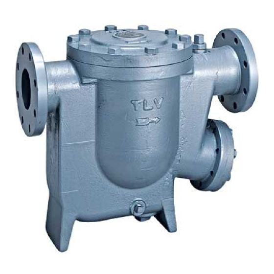
Summary of Contents for TLV J10
- Page 1 172-65237A-01 (J10) 11 March 2021 Float Dynamic Steam Trap Manufacturer 881 Nagasuna, Noguchi, Kakogawa, Hyogo, 675-8511 Japan Tel: [81]-(0)79-422-1122 Fax: [81]-(0)79-422-0112 Copyright © 2021 by TLV CO., LTD. All rights reserved...
-
Page 2: Table Of Contents
If detailed instructions for special order specifications or options not contained in this manual are required, please contact TLV for full details. This instruction manual is intended for use with the model(s) listed on the front cover. It is necessary not only for installation, but for subsequent maintenance, disassembly/reassembly and troubleshooting. -
Page 3: Safety Considerations
The three types of cautionary items above are very important for safety: be sure to observe all of them as they relate to installation, use, maintenance, and repair. Furthermore, TLV accepts no responsibility for any accidents or damage occurring as a result of failure to observe these precautions. - Page 4 Use only under conditions in which no water hammer will occur. The impact of water hammer may damage the product, leading to fluid discharge, which may cause burns or other injury. 172-65237A-01 (J10) 11 Mar 2021...
-
Page 5: Checking The Piping
** Valve No. is displayed for products with options. This item is omitted from the nameplate when there are no options. NOTE: The minimum differential pressure is 0.05 MPa. Do not use this product with a differential pressure less than this. 172-65237A-01 (J10) 11 Mar 2021... -
Page 6: Operation
(B), opening the large orifice on the main valve seat (C) instantly. As condensate discharges through the main valve seat orifice at a high velocity, condensate in the equipment and trap inlet pipe is also discharged. Steam Condensate 172-65237A-01 (J10) 11 Mar 2021... -
Page 7: Configuration
36 Float Cover 11 Snap Ring 24 Lock Release Valve Body 37 Float Cover Retainer Lock Release Valve Body 12 Stopper Ring 38 Drain Plug Gasket Gasket 13 Cover Gasket 26 V-ring Packing 39 Plug Gasket 172-65237A-01 (J10) 11 Mar 2021... -
Page 8: Installation
If there is a problem, determine the cause using the “Troubleshooting” section in this manual. Tolerance Angle for Installation - 5° Make sure the trap is installed with the raised lettering on the body horizontal. 172-65237A-01 (J10) 11 Mar 2021... -
Page 9: Operation
(tighten to a torque of 15 Nm (11 ftlb)). Do not leave the lock release valve open during regular operation. Always be sure CAUTION to close the lock release valve after eliminating air binding or steam-locking. 172-65237A-01 (J10) 11 Mar 2021... -
Page 10: Maintenance
Check for the build-up of scale V-ring Packing: Check for warping or damage Lock Release Valve Stem: Check for build-up or wear on seating surfaces Lock Release Valve Seat: Check for build-up, damage or wear 172-65237A-01 (J10) 11 Mar 2021... -
Page 11: Disassembly / Reassembly
Lift up and out Place on the ledge inside the body, making sure the rounded side is on top Float Remove, being careful Insert, being careful not to scratch or misshape not to scratch the polished surface 172-65237A-01 (J10) 11 Mar 2021... - Page 12 Replace with a new set of piston rings piston * Main Valve Unit Exhaust Holes Spring Washer Turn Stopper Bolt Main Valve Stopper Ring Main Valve Seat O-ring Main Valve Bolt U-Nut Spring Washer Turn Stopper Cylinder Piston Ring Set Piston 172-65237A-01 (J10) 11 Mar 2021...
- Page 13 - If drawings or other special documentation were supplied for the product, any torque given there takes precedence over values shown here. * Values represent tightening torque for threads that are wrapped with 3 – 3.5 turns of sealing tape. 172-65237A-01 (J10) 11 Mar 2021...
-
Page 14: Troubleshooting
Gasket deterioration or damage Replace with new gasket(s) from a place other Improper tightening torques were used Tighten to the proper torque than the outlet Float is frequently Water hammer has occurred Study and correct the piping damaged 172-65237A-01 (J10) 11 Mar 2021... -
Page 15: Tlv Express Limited Warranty
TLV EXPRESS LIMITED WARRANTY Subject to the limitations set forth below, TLV Corporation, a North Carolina corporation (“TLV”) warrants that products which are sold by it, TLV CO., LTD., a Japanese corporation (“TLVJ”) or TLV International, Inc., a Japanese corporation (“TII”), (hereinafter the “Products”) are designed and manufactured by TLVJ, conform to the specifications... - Page 16 WARRANTY NOT NEGATED HEREBY, AND ANY IMPLIED WARRANTY NOT NEGATED HEREBY, INCLUDING THE IMPLIED WARRANTIES OF MERCHANTABILITY AND FITNESS FOR A PARTICULAR PURPOSE, DO NOT COVER, AND NEITHER TLV, TII NOR TLVJ WILL IN ANY EVENT BE LIABLE FOR, INCIDENTAL OR CONSEQUENTIAL DAMAGES, INCLUDING, BUT NOT LIMITED TO LOST PROFITS, THE COST OF DISASSEMBLY AND SHIPMENT OF THE DEFECTIVE PRODUCT, INJURY TO OTHER PROPERTY, DAMAGE TO BUYER’S OR THE FIRST...
Need help?
Do you have a question about the J10 and is the answer not in the manual?
Questions and answers