Sign In
Upload
Manuals
Brands
Sensia Manuals
Controller
JISKOOT InSpec Sampler
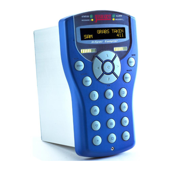
Sensia JISKOOT InSpec Sampler Controller Manuals
Manuals and User Guides for Sensia JISKOOT InSpec Sampler Controller. We have
1
Sensia JISKOOT InSpec Sampler Controller manual available for free PDF download: Application/Operation Manual
Sensia JISKOOT InSpec Sampler Application/Operation Manual (127 pages)
Brand:
Sensia
| Category:
Controller
| Size: 4 MB
Table of Contents
Table of Contents
3
Section 1: Introduction
11
Intended Use
11
Identifying the Parts of the Inspec Front Display
11
Front Panel
11
Basic Operation of the Instrument (Start, Stop, Reset, Manual)
14
Section 2: Common Software Features
15
Main Features
15
Inspec Security
15
Common Security Menu Items
15
Navigating the Inspec Display
17
Basic Screen Layout
17
Data Entry
18
Numeric Entry
18
Alphanumeric Entry
19
Password Entry
19
Questions & Decisions
19
Select/Assign Key
19
Registers
20
Register Mode Options
20
Display Setup
22
Scroll Setup
22
Display Items
22
Display Dec
22
Engineering Display
22
Bar Graph 1
23
Bar Graph 2
23
The Alarms Menu
24
Set Display Text
25
Set Source Register
25
Set Active Register
25
Invert Active
25
Minimum Value
25
Maximum Register
25
Invert Rslt
25
Hysteresis (%)
25
Set Phases
25
Alarm Delay
25
Email Notification
26
Inhibit Trim
26
Security
26
The Systems Menu
26
Inspec ID
26
Set Date/Time
26
Email Setup
27
Serial Ports
28
Modbus Tcp Slave
30
Modbus Tcp Master
30
Ip Settings
30
User Commands
31
Records and Logs
35
Generate Report
35
Print
35
Delete Batches
36
Email
36
Log Setup
38
Software Description
38
Operating System
38
Files
38
Section 3: Data Communications
39
What Is It
39
One Bit at a Time, or a Whole Byte
39
Parallel Transmission
39
Serial Transmission
39
Simplex, Half Duplex or Full Duplex
39
Simplex
39
Half Duplex
39
Full Duplex
39
The Right Connection
40
Line Termination and Fail-Safe
41
Section 4: Ip Settings
42
Ip Settings
42
What Is an IP Address
42
What Do IP Addresses Look Like
42
Configure DHCP
43
IP Address
43
Subnet Mask
43
Default Gateway
44
Primary DNS
44
Secondary DNS
44
SMTP URL Address
45
Print URL Address
45
NTP URL Address
45
View MAC Address
45
NTP Setup (Network Time Protocol Setup)
45
Resolving Ip Addresses
45
Email - Default Smtp Port = 25
45
Network Printer - Default Port = 515
46
Ntp Time - Default Port = 123 (Udp/Ip Protocol)
46
Modbus Tcp - Default Network Port = 502
46
Section 5: Sd Card File System
47
System Directory
47
Modlog.csv
47
Reglog.csv
47
Rebootlog.csv
47
Seclog.csv
47
Users.bin
47
Backup Directory
47
Temp Directory
47
Csdata
48
Images
48
System
48
Batch Directory
48
Log.txt
49
Log.csv
49
Al_Ph.csv
49
Report.txt
50
Report.htm
50
Section 6: Ftp File System Access
51
Section 7: Insitu Programming
52
Programming from the Bootloader
52
Automatic Software Update Via the Bootloader
52
Manual Software Update Via the Bootloader
53
Upgrading Existing Software Via Testcard
54
Upgrading - the Upgrade Data Folder
55
Upgrading the Bootloader Software Via the Application
56
Section 8: Sd Card System Files
58
Section 9: Modbus Information
61
General
61
Invalid Addresses
61
MODBUS Serial Set-Up
61
Ethernet Modbustcp Setup
61
Node Number
61
Mode
61
Ascii
62
Rtu
62
Tcp
62
Word Order
62
Functions Supported
62
Modbus Addresses
63
Comms Data Registers
63
RTU Delay (Serial Only)
63
String Size
63
Float Size
63
Start Offset
63
Modbus Slave
64
Modbus Master
64
General
64
Queries Blocks
64
Modbus Poll Delay (Serial Only)
64
Modbus Retries
64
Section 10: User Commands
65
Introduction
65
Command Types
65
Section 11: User Configurable Logic (Ucl)
67
How Does Ucl Run
67
How to Write Aucl Program
67
How to Use Build - Part 1
67
How to Execute Aucl Program
67
What Makes up Aucl Program
68
Types and Type Casting
69
Integer Type
69
Floating Point Type
69
Boolean Type
69
Register Names
69
Casting
69
Arithmetic Operators (+, -, *, /, %)
70
Boolean Logical Operators (&&, ||, ^^, !)
70
Boolean Comparison Operators (==, !=, >, <, >=, <=)
70
Bit-Wise Operators (&, |, ^)
71
Shift Operators (>>, <<)
71
Pointer Arithmetic Operators
71
Complex Math Operators (Log, Ln, Pow, Sin, Cos, Tan, Asin, Acos, Atan)
71
Log Example
71
Ln Example
71
Pow Example
72
Sin Example
72
Cos Example
72
Tan Example
72
Asin Example
72
Acos Example
72
Atan Example
72
Rand Example
72
Operators Decision Making (? :)
72
Operator Priority and Parenthesising
73
Operators: Conditional Jump Loop Labels (IF$LABEL, $LABEL:)
73
Section 12: Flow Weighted Averaging
76
Section 13: Pid Blocks
77
Section 14: Storing Configuration Backups
78
Section 15: Restoring Configuration Backups
79
Section 16: System Start up Menu
80
Exit
80
Toggle Wdog
80
Enable Debug
80
Default Uk
80
Default Us
80
Default Modbus
80
Clear Modbus Addrs
80
Default Files
80
Wipe Instrument
80
Format Sd Card
81
Startup Ctrl
81
Clear Reg Check
81
Register Editor
81
System Backup
81
System Restore
81
Section 17: Web (Http) Interface
82
Section 18: Svg Schematic - Web Interface
83
Section 19: Remote Io Module
87
Field Connections
87
Connect with Web Interface
87
Remote Adc Device
88
Remote Dac Device
89
Remote Digital Device
90
Remote Pulse Device
90
Section 20: Remote Io Web Page
92
Section 21: Safety Information
93
Section 22: Installation Details
94
General
94
Location
94
Mounting
94
Section 23: Making Connections
95
Field and Power Connections (Rear)
95
Input Power
95
Earthing Requirements
95
Shielded (Screened) Cables
96
Section 24: Field Connections
97
Cable Screens & Drain Wires
97
Plug No's 1, 2, 3 & 4
97
Relay Outputs (4 Off)
97
Plug No. 5
98
Rs422 & Rs485 Terminology
98
Rs422 & Rs485 Termination
99
Rs422 & Rs485 Connections
99
Plug No. 6
99
DC Power (1 Off)
100
Dual Function Digital Inputs/Outputs (4 Off)
100
Voltage or Current Pulse Inputs (2 Off)
100
4-20Ma ANALOGUE OUTPUT (2 Off)
101
4-20Ma ANALOGUE INPUT (3 Off)
101
Section 25: Instrument Specifications
102
General Specifications
102
Insulation Co-Ordination
103
Ac Power Inlet Creepage/Clearance
103
Relay Outputs Creepage/Clearance
103
Compliance to International Standards
103
Section 26: Instrument Breakdown
104
Disassembly
104
Reassembly
104
Section 27: Printed Circuit Boards
105
Fitting & Removal
105
Main Case/Extrusion
105
Front Panel
105
Printed Circuit Board Configuration
106
Pcb Handling Precautions
106
Pcb Identification & Description
106
F3174 Configuration
107
Battery Replacement
107
F3175 Configuration
108
Switch Settings for 'Sw1
108
Trigger Threshold Adjustment
108
F3176 Configuration
109
Display Contrast Adjustment
109
Section 28: Frequently Asked Questions
111
Battery Storage Life
111
Data Retention Time
111
Lcd Backlight Life Expectancy
111
Section 29: Maintenance / Entretien
112
Health and Safety Precautions / Precaution Sante Et Securite
112
Cleaning the Inspec
112
Section 30: Troubleshooting
113
Solving Common Problems
113
Power & Battery Problems
113
Display Problems
113
Serial Problems
113
Section 31: Support
115
Contact Information
115
Recommended Spares
115
First 10 Years Operation
115
Years Operation
115
Repackaging for Shipment
115
Section 32: Definition of Terms & Symbols
116
Abbreviations & Acronyms
116
Symbols / Symboles
118
Appendix A: Inspec Controller Panel Cut-Out Detail
120
Appendix B: Installation Sequence (Safe Area Unit)
121
Appendix C: Remote I/O (Rio) Configuration
124
Appendix D: Publisher Notes
126
Advertisement
Advertisement
Related Products
Sensia 5072735
Sensia 5072740
Sensia 5073290
Sensia 5073295
Sensia CLIF MOCK CD-20A
Sensia CLIF MOCK TC2000
Sensia INSTRUCT PCP
Sensia QRATE HCC2
Sensia Categories
Measuring Instruments
Controller
Control Systems
Gateway
Laboratory Equipment
More Sensia Manuals
Login
Sign In
OR
Sign in with Facebook
Sign in with Google
Upload manual
Upload from disk
Upload from URL