Table of Contents
Advertisement
Quick Links
Advertisement
Table of Contents

Subscribe to Our Youtube Channel
Related Manuals for Door Knox VDP300


Summary of Contents for Door Knox VDP300
- Page 1 DoorKnox PhoneSEE WiFi Box xVDP300 © 2021 System Q Ltd DoorKnox.com...
-
Page 2: Table Of Contents
VDP300 Table of Contents Part 1 Introduction 1 Key Features ................................1 Part 2 Connections 1 Overview ..................................2 2 Input Connections ..............................3 3 Output Connections ..............................4 Part 3 LED Indicators Part 4 Controls Part 5 Mounting Part 6 Smart App Part 7 Network Setup 1 EZ Mode Setup ................................ -
Page 3: Part 1 Introduction
Introduction Introduction The VDP300 PHONESEE WiFi DoorKnox box is used to integrate DoorKnox cameras and monitors for remote viewing and door relay control via the "Tuya Smart" application. The VDP300 is installed between DoorKnox cameras and DoorKnox monitors to intercept the images to stream and connect with the Tuya Smart app via the WiFi or via a Ethernet network cable connected to a router. -
Page 4: Part 2 Connections
Connections 2.1 Overview The VDP300 is installed between DoorKnox cameras and DoorKnox monitors in order to intercept the images to stream and connect with the Tuya Smart app via the WiFi or an Ethernet network cable connected to a router. -
Page 5: Input Connections
Connections 2.2 Input Connections © 2021 System Q Ltd DoorKnox.com... -
Page 6: Output Connections
VDP300 2.3 Output Connections © 2021 System Q Ltd DoorKnox.com... -
Page 7: Part 3 Led Indicators
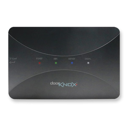
LED Indicators LED Indicators Power LED ON = Device is powered Note:- During boot-up the WIFI, SERVER and SIGNAL LEDs will be ON Once boot-up is complete the WIFI, SERVER and SIGNAL LEDs will turn OFF WIFI LED ON = Network ok OFF = Network disconnected Fast flash = Configuring network Slow flash = EZ mode... -
Page 8: Part 4 Controls
The control buttons on the back of the VDP300, are shown below. S-link (Only use if the SERVER light is not on solid) Short Press (>1s) = Restarts the VDP300 and starts "EZ Mode", the WIFI LED will flash slowly. See... -
Page 9: Part 5 Mounting
Mounting Mounting The VDP300 Hub can be mounted using the screws provided and the mounting holes on the rear. © 2021 System Q Ltd DoorKnox.com... -
Page 10: Part 6 Smart App
VDP300 Smart App Tuya Smart App Terms and Conditions 1. Download “Tuya Smart” app via the Apple store or Google Play store 2. Open the app to and register an account. © 2021 System Q Ltd DoorKnox.com... -
Page 11: Part 7 Network Setup
Mode. 7.1 EZ Mode Setup The VDP300 WiFi box can be paired up with a router (wirelessly) using the S-link pairing button on the back of the VDP300 and the "Tuya Smart" app. 1. Press the S-link to start the EZ pairing. The WiFi LED will flash slowly when in pairing mode 2. - Page 12 VDP300 4. At the top right, select "EZ Mode" 5. Tick "Next Step", then select Next 6. Select the WiFi Hub (Router or Access point) and enter the WiFi password, then select Next © 2021 System Q Ltd DoorKnox.com...
- Page 13 Network Setup 7. The WiFi LED will flash quickly once it starts pairing 8. Once paired the app will show the device is Added © 2021 System Q Ltd DoorKnox.com...
-
Page 14: Cable Mode Setup
"Tuya Smart" application. 1. Connect an Ethernet (CAT5 / 5e / 6) cable to the RJ45 port on the back of the VDP300. (The network port LED indicators will light up once connected) 2. - Page 15 Network Setup 6. Tick to confirm LED is flashing, then select Next 7. The app will search the device via the network Note: Reset the device if the search fails, see - Controls to reset 8. Select the device to add ©...
- Page 16 VDP300 9. The app will then try to add the device via the network 10. The app will show the device is Added © 2021 System Q Ltd DoorKnox.com...
-
Page 17: Ap Mode Setup
Network Setup 7.3 AP Mode Setup The VDP300 WiFi box can be paired up with a router (wirelessly) using the AP button on the back of the VDP300 and the "Tuya Smart" app. 1. Press the AP button to set the VDP300 to access point mode. - Page 18 VDP300 5. At the top right, select "AP Mode" 6. Tick "Next Step", then select Next 7. Use the switch button to connect to the main WiFi Hub (Router or Access point). © 2021 System Q Ltd DoorKnox.com...
- Page 19 Network Setup 8. Go back to the Tuya Smart app and select Next 9. Click "Go to Connect" to connect the mobile phone back to the "SmartLife-xxxxxx" WiFi. Then go back to the Tuya Smart app. © 2021 System Q Ltd DoorKnox.com...
- Page 20 VDP300 10. The WiFi LED will flash quickly once it starts pairing 11. Once paired the app will show the device is Added © 2021 System Q Ltd DoorKnox.com...
-
Page 21: Part 8 Using The App
Using the App 8.1 Visitor Calls When a visitor presses the call button on a door camera connected to the VDP300 a push notification will appear on the phone. To answer the call press the notification. 8.2 App Controls Once connected to the device the image and control options will display. -
Page 22: Part 9 Sd Card
VDP300 SD Card For local recording on the VDP300 itself an SD card must be installed. Recording time will vary dependent upon: SD card size. The maximum size supported is 32G class 10TF card. Remove power from the camera when inserting or removing the SD card in the "TF Card" slot. -
Page 23: Part 11 Doorknox Wiring
DoorKnox Wiring DoorKnox Wiring 11.1 Cameras All our door cameras have connection cables terminated into the same 7 colour coordinated wires. 4 wires are used to connect to the monitor and then 2 of the 3 remaining wires are used to connect to an electronic door lock. -
Page 24: Cable Runs
VDP300 11.5 Cable Runs The maximum achievable cable run is limited by the voltage drop in the chosen cable and also the quality of the cable used for the video cores which can cause signal loss and interference. Resistance differs depending on the cable used and the higher the resistance the more the voltage drops hence the shorter cable run achievable. -
Page 25: Part 12 Troubleshooting
General Maintenance · Ensure that the VDP300 is within signal range of the WiFi, ensure there is no large metal objects in between the VDP300 or the Router ·... -
Page 26: Part 14 Specification
VDP300 Specification Communication WiFi 2.4GHz Input Connections 2x Door Cameras / 2x Auxiliary Cameras Outputs Connections 2x Door Cameras / 2x Auxiliary Cameras Consumption 600mA (Max) SD Card Micro SD / 2GB – 32GB Class 10TD Input Voltage 12V DC... -
Page 27: Part 15 Conditions
Conditions Conditions All specifications are approximate. System Q Ltd reserves the right to change product specifications or features without notice. Whilst every effort is made to ensure that these instructions are complete and accurate, System Q Ltd cannot be held responsible for any losses, no matter how they arise, from errors or omissions in these instructions, or the performance or non-performance of the equipment refered to. -
Page 28: Index
VDP300 Index - K - Key Features - A - - L - Android LED Indicators AP Mode 9, 15 Lights 8, 9, 12, 15, 19 Apple - M - - B - Maintenance Monitor Connections Back plate Monitoring Buttons... - Page 29 Index Signal Signal LED Size S-Link Snapshot Specification Switch - T - Talk Talkback Tuya Smart - U - Unlock - V - Visitors Voltage - W - Wall WiFi 9, 15 WIFI LED © 2021 System Q Ltd DoorKnox.com...
Need help?
Do you have a question about the VDP300 and is the answer not in the manual?
Questions and answers