Table of Contents
Advertisement
Quick Links
Advertisement
Table of Contents

Related Manuals for Door Knox xVDP207


Summary of Contents for Door Knox xVDP207
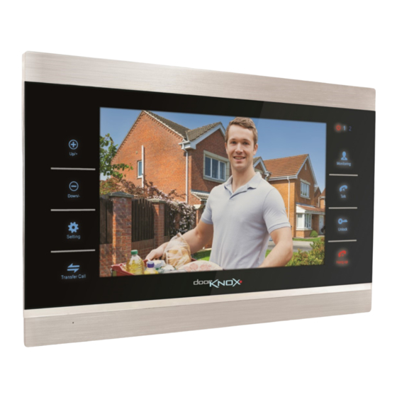
- Page 1 DoorKnox Video Door Entry 7 inch Monitor xVDP207 © 2021 System Q Ltd DoorKnox.com...
-
Page 2: Table Of Contents
VDP210 Table of Contents Part 1 Introduction 1 Key Features ................................1 Part 2 Controls & Features Part 3 Mounting Part 4 Connections and Wiring 1 Cameras ..................................4 2 Monitors ..................................5 3 Powering Cameras ..............................5 4 Powering Monitors ..............................5 5 Cable Runs ................................ -
Page 3: Part 1 Introduction
Introduction Introduction The new and improved DoorKnox VDP207 and VDP210 from serial numbers HCA01001 and HCB00401 onwards have many new features. With a stylish brushed aluminium & gloss black finish and quality build the DoorKnox is ideal for retail and commercial projects. Our touch button monitors provide you with full control of your door entry system and are available in a choice of two sizes;... -
Page 4: Part 2 Controls & Features
VDP210 Controls & Features Mounting The mounting place is secured to the mounting surface and then the monitor slots on to it. There is a large hold in the centre of the mounting plate to allow the cables to pass through. ©... -
Page 5: Part 4 Connections And Wiring
Connections and Wiring Connections and Wiring © 2021 System Q Ltd DoorKnox.com... -
Page 6: Cameras
VDP210 4.1 Cameras All of our door cameras have connection cables terminated into the same 7 colour coordinated wires. 4 wires are used to connect to the monitor and then 2 of the 3 remaining wires are used to connect to an electronic door lock. The common (COM) wire is always used along with either the normally open (NO) or normally closed (NC) wire depending on the lock type, power for the lock is separate as the Door Lock relay does not provide power output. -
Page 7: Monitors
Connections and Wiring 4.2 Monitors Every monitor is supplied with 6x 4 wire y-leads, 1x 2 wire y-lead and 1x 3 wire y-lead. The 4 wire y-leads are terminated into 4 pin plugs which are simply inserted into the sockets on the rear of the monitor. -
Page 8: Cable Runs
VDP210 4.5 Cable Runs The maximum achievable cable run is limited by the voltage drop in the chosen cable and also the quality of the video cable which can cause signal loss and interference. Resistance differs depending on the cable used and the higher the resistance the more the voltage drops hence the shorter cable run achievable. -
Page 9: Part 5 Menu Navigation
Menu Navigation Menu Navigation The Main Menu is entered by pressing the Setting button and navigated by using + for up or left, and – for down or right. Once in the menu the Setting button is used to select the feature. To go back at any time or to exit the menu use the Hang Up button. -
Page 10: Camera Switch
VDP210 6.2 Camera Switch As default Door Cam 2 and CCTV (Auxillary) Cameras are turned off. 1. From the menu select Settings and then System 2. Go to Door Cams / CCTV Cams 4. Select Channel 5. Then change Status in the list to ON. ©... -
Page 11: Part 7 Using The Door Entry System
Using the Door Entry System Using the Door Entry System 7.1 Visitor Calls When a visitor presses the call button on a door camera the ringtone will be played and their image will be displayed on all door monitors. To answer the call press the Talk button Door Camera Number Outdoor Door / Camera Relay Unlock... -
Page 12: Intercom (Monitor To Monitor Audio Only)
VDP210 7.2 Intercom (Monitor to Monitor Audio only) Press and hold Transfer Call button to show different monitor extension IDs Press the Up and Down to select the different monitor IDs then select using Setting to call another monitor. To answer the call press the Talk button on the receiving monitor. To end the call press the Hang Up Button. -
Page 13: Monitoring Cameras
Using the Door Entry System 7.3 Monitoring Cameras To monitor any camera press the Monitoring button to cycle through camera inputs. When monitoring a door camera open two way audio by pressing the Talk button. Unlock door by pressing the Unlock button. When monitoring cameras the door monitor will return to standby after 60 seconds of inactivity. -
Page 14: Part 8 Monitor Features
VDP210 Monitor Features 8.1 Standby Mode The standby screen mode can be set to either: Clock mode - which shows time date and the notifications bar at the bottom Digital Photo Frame mode - Which shows a sideshow / image which can be accompanied with background music. - Page 15 Monitor Features Notifications 1. Call - During any Door Camera call, the monitor automatically captures a snapshot or records video. 2. Messages - Automatic Video Message recording when no one answers the call on a monitor. 3. Motion - Motion can be set to record when motion is triggered at a door camera or CCTV (Auxiliary) Camera.
-
Page 16: Digital Photo Frame Mode
VDP210 8.1.2 Digital Photo Frame Mode Digital photo frame mode will play the pictures on the SD card in standby. The monitor will create a "Photo" folder on the SD Card, any pictures required for the system to play need to be placed in this folder. Remove the SD Card and place into a compatible device, like a PC or Phone. -
Page 17: Motion Detection
Monitor Features 8.2 Motion Detection Can be setup to trigger recording to the SD card in the monitors connected and also be reviewed later as a notification from the menu. 1. From the menu select Settings 2. Go to Door Cams / CCTV Cams 3. -
Page 18: Motion Detection Preview
VDP210 8.2.1 Motion Detection Preview When motion is detected then the camera which is activated can be set to display on the monitor. To turn Motion Detection Preview on:- 1. From the menu select Settings and then System 2. Set Motion Detection Preview to ON NOTE If Digital Photo Frame is running and Motion is triggered then the motion event will trigger and show the motion event. -
Page 19: Messages & Availablility Status
Monitor Features 8.3 Messages & Availablility Status The monitor supports Automated Message Recording if nobody answers the call on a monitor. The monitor will handle this differently depending on your availability status. Message needs to be turned on in the Door Camera First, Message Time can also be set, go to:- 1. - Page 20 VDP210 Availability Status This is set in the Main Menu on the monitor Available - The call will go through to the monitor and ring for 30 seconds. Then "Please leave a message" audio will play at the camera, then the caller can leave a message. Unavailable - The call will go straight to "Please leave a message"...
-
Page 21: Local Relay Unlock
Monitor Features 8.4 Local Relay Unlock The local relay to the monitor can be setup to unlock a door from the monitor itself without having to setup a install push button separate to the monitor. This can be activated in two ways:- Option 1. -
Page 22: Part 9 Troubleshooting
VDP210 Troubleshooting 9.1 Signal Loss / No Image Poor Connections - A poor lead connection may cause signal loss or interference so check that each component is firmly plugged in and any joints (soldered or otherwise) have been made well and solid with no shorts or crossed wires. -
Page 23: Part 11 Vdp207 Specification
VDP207 Specification VDP207 Specification Screen Size 7” Video Input CVBS Resolution 800 x 600 Camera Input 2x Door Cameras / 2x Auxiliary Cameras Door Monitor Inputs Door Monitor Outputs 1 (5 Auxiliary Max) TV Monitor Outputs 1 (720 x 576) SD Card Micro SD / 2GB –... -
Page 24: Part 12 Conditions
VDP210 Conditions All specifications are approximate. System Q Ltd reserves the right to change product specifications or features without notice. Whilst every effort is made to ensure that these instructions are complete and accurate, System Q Ltd cannot be held responsible for any losses, no matter how they arise, from errors or omissions in these instructions, or the performance or non-performance of the equipment refered to. -
Page 25: Index
Index Index Powering Cameras - S - - B - Setting - T - Back plate Buttons Talk 2, 9 - C - Transfer Call - U - Cable Runs Calls Camera Unlock Cameras Checking Cleaning - V - Connections Controls Visitors Volume...
Need help?
Do you have a question about the xVDP207 and is the answer not in the manual?
Questions and answers