Table of Contents
Advertisement
Quick Links
Advertisement
Table of Contents

Subscribe to Our Youtube Channel
Related Manuals for Streetwize LeisureWize EMOVE EM303A


Summary of Contents for Streetwize LeisureWize EMOVE EM303A
- Page 1 EM303A Caravan Manoeuvring System...
-
Page 2: Table Of Contents
TABLE OF CONTENTS Package contents (Parts list) Introduction Intended use Specifications Installation - safety guidelines Installation - mechanical components Installation - electrical/electronic components Installation - twin axle Operation - safety guidelines Operation - motor units Operation - remote control handset Operation - electronic control unit Operation - getting started Operation - hitching and unhitching... -
Page 3: Introduction
INTRODUCTION Congratulations on choosing the emove EM303A caravan manoeuvring system. This has been produced according to very high standards and has undergone careful quality control procedures. Simply by using the remote control handset you can move your caravan effortlessly into any position required within operating guidelines. -
Page 4: Installation - Mechanical Components
Check the minimal installation dimensions of the manoeuvring system based on figure 14. Only use adapters and accessories that are supplied or recommended by the manufacturer. Check that the caravan is disconnected from the battery supply and the mains electrical supply. Check that the tyres are not over worn and do have the same size and design (fitting to new or nearly new tyres is the best option). -
Page 5: Installation - Electrical/Electronic Components
Adequate ground clearance: Please notice that the min. distance between the lowest line of motors and ground is 110mm, no matter what kind of chassis or install situation. Make sure that the main cross bar (3) is positioned in the middle of the caravan (the centre of the bar is marked). - Page 6 Table. A Table. B FRONT OF AXLE FITTING REAR OF AXLE FITTING (4,6mm cables) (4,6mm cables) Motor unit A Positive (+) cable to terminal 4 Motor A Positive (+) cable to terminal 1 Motor unit A Negative (-) cable to terminal 3 Motor A Negative (-) cable to terminal 2 Motor unit B Positive (+) cable to terminal 2 Motor B Positive (+) cable to terminal 3...
-
Page 7: Installation - Twin Axle
Caution! Make sure that you do not reverse the Positive (+) and Negative (-) connections. Incorrect connection (reverse polarity) will result in damage to the control unit. Connect the battery cables (14 & 15) to the control unit (4). Seal the 25mm hole in vehicle under body using plastic body sealant. Installation of the caravan manoeuvring system is now complete. -
Page 8: Operation - Safety Guidelines
OPERATION - SAFETY GUIDELINES Practice operating the manoeuvring system in an open area before using for the first time. This is to fully familiarise yourself with the handset / manoeuvring system operation. Before use, always check the caravan manoeuvring system for any damage. When towing or moving the caravan please be aware, at all times, that ground clearance is reduced when the manoeuvring system has been fitted. -
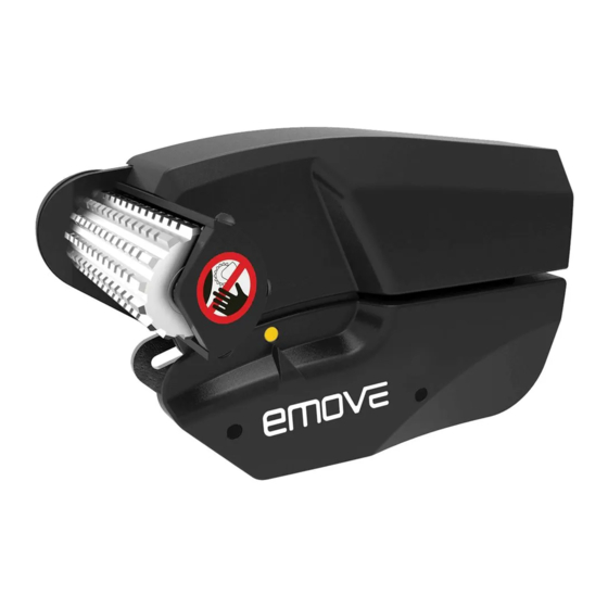
Page 9: Operation - Motor Units
OPERATION - MOTOR UNITS The manoeuvring system has two motor units (1 & 2). In general they are mounted in front of the axle of the caravan. Both units are identical but cannot be switched. Fig. 4 Aluminium drive roller 12V Motor Motor connection terminals (+ and -) Motor for automatic engaging system... -
Page 10: Operation - Electronic Control Unit
The slide switch (Fig. 5A) also acts as an The automatic engaging system: To activate the automatic engaging system of the motor powered rollers on the tyre, press the two buttons for engaging (Fig. 5I) or disengaging (Fig. 5J) for at least three seconds. The blue LED (Fig. 5K) will blink fast during these three seconds and every second there will be a beep. -
Page 11: Operation - Getting Started
Blue LED is blinking (2 times blinking, break, 2 times blinking, break etc.): Battery voltage too low (<10V). Battery needs to be recharged. Blue LED is blinking (4 times blinking, break, 4 times blinking, break etc.): Battery Voltage too high (over charged). -
Page 12: Operation - Hitching And Unhitching
In addition, the left forward (Fig. 5D) and right reverse (Fig. 5G) buttons or right forward (Fig. 5E) and left reverse (Fig. 5F) buttons may be pressed at the same time to turn the caravan around on its own axis without moving forward or backward (this function just can work under the -axle When you drive straight forwards or reverse (press button 5B or 5C), it is also possible to adjust the direction... -
Page 13: Trouble-Shooting
Regularly clean the drive units with a water hose to dissolve mud etc. Please check regularly the distance between the rollers and the tyres. In the neutral (fully disengaged) position this must be about 20mm. Once a year have your caravan manoeuvring system maintained and visually inspected. This inspection must include all the bolt/nut connections, the cables and electrical connections and lubrication of movable parts/joints. - Page 14 Check if there is any distortion signal (other transmitter, high power cables, Wifi etc.) that disturbs a good communication between remote control handset and control unit. If there is no good communication between the control unit and remote control handset, the manoeuvring system will not function and the green LED on remote control handset is blinking.
- Page 20 Five Year Warranty Your emove caravan mover is covered by a five years’ parts and labour warranty (when registered). You are covered against reasonable use of your caravan mover for the period of five years. It does not cover against misuse or accidental damage of the e caravan mover.
Need help?
Do you have a question about the LeisureWize EMOVE EM303A and is the answer not in the manual?
Questions and answers