Arjo Carevo Maintenance And Repair Manual
Hide thumbs
Also See for Carevo:
- Quick reference manual-use (7 pages) ,
- Instructions for use manual (56 pages)

Related Manuals for Arjo Carevo


Summary of Contents for Arjo Carevo
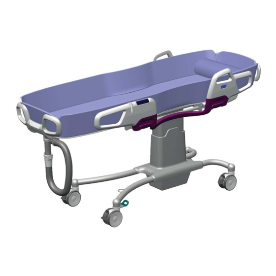
- Page 1 MAINTENANCE AND REPAIR MANUAL Carevo For internal use only! 09.BA.03_4EN • 11/2021...
-
Page 2: Table Of Contents
MRM Carevo NOTE Before using this Manual you must have taken part of and understood the Safety Precautions 09.NE.01 Blue text indicates changes compared to the previous manual. Index Preventive Maintenance Schedule ..........3 Procedures not included in PMS ..........4 Service Procedures................ -
Page 3: Preventive Maintenance Schedule
MRM Carevo Preventive Maintenance Schedule (PMS) Preventive Maintenance Schedule (PMS) NOTE All caregiver obligations according to Instructions for Use are to be checked when performing the Qualified personnel Service WARNING The points on this checklist are the minimum the manufacturer recommends. In some cases due to heavy use of the product and exposure to aggressive environment, more frequent inspections should be carried out. -
Page 4: Procedures Not Included In Pms
Preventive Maintenance Schedule (PMS) MRM Carevo Procedures not included in PMS After performing a replacement, check Replace the the involved functions according to control panel PMS. SP 9, page 15 Setting of the potentiometers SP 13 page 21 Replace the... -
Page 5: Service Procedures
MRM Carevo Service Procedures Service Procedures SP 1. Check that the latest updates have been implemented Check if there are any Field Safety Notices or Technical Advisory Notices (FSN:s and TAN:s) that have been published since the last service. Field Safety Notice: information notice informing of what actions must be taken in a Field Safety Corrective Action. - Page 6 Service Procedures MRM Carevo SP 2. Check battery Check the battery The battery condition tester will load the battery with a high current for a short time and this will show the battery condition on a meter. The battery power tester will load the battery...
- Page 7 MRM Carevo Service Procedures SP 3. Check all vital parts for corrosion and damage Visually check and correct so that the intended function is not impaired: • (a) Stretcher with flexible hip part • (b) Gables • (c) Chassis covers •...
- Page 8 Service Procedures MRM Carevo SP 4. Check mechanical attachments Visually check: (Torque=T, Locking nut =L, Lo= Loctite) NOTE • (a) Side support parts, T+Lo Screws and bolts attached with Loctite should • (b) Side support bearings and torsion not be checked by tools but manually to test if springs the jointing/component is securely fitted.
- Page 9 MRM Carevo Service Procedures Check the safety stop function Check that the microswitch (a) stops the stretcher from lowering if an object is hit. If not: • Check cabling (b) to PCB J3. If the cabling is shortcut the safety stop will not work. If the cabling is cut the actuator will not operate.
- Page 10 Always refer to the SWL identified on the actual hoist equipment Applicable load test: • Model: Carevo • SWL: 200 kg (440 lbs) • Test load: 200 kg (440 lbs) • Use the ArjoHuntleigh load test equipment and refer to SP015 for general information on load testing.
- Page 11 MRM Carevo Service Procedures SP 7. Inspect Castors Do a a validation concerning wear, movement of every swivel/ wheel and appearance as follows. NOTE The castors must be properly cleaned according to the customer obligations before starting. 1. Lay the product down onto a flat surface.
- Page 12 (d) and locking nut (a) (torque see page 23). NOTE If it is a single replacement and without straight steering on Carevo: reuse thin washer as position (c) 3. Check the function of the new castor Straight steering 1. Unscrew the locking nut (a) pull off the cas- tor and slide out the old screw 2.
- Page 13 MRM Carevo Service Procedures SP 8. Inspect handles of safety side Perform the visual inspection in case of any potential wear or damage to handles, which are used to lock or unlock safety sides. Pay attention to the areas indicated by the arrows below.
- Page 14 Service Procedures MRM Carevo SP 9. Perform full feature functionality test Check functions according to the following table as a final test after performed service procedures: Carevo Function Activation Demands for approval Lift up/down Panel Activation/deactivation Rotation and swivelling of castors...
- Page 15 MRM Carevo Service Procedures SP 10. Replace the control panel 1. Remove the battery 2. Remove membrane on control panel 3. Remove battery box cover (a) with 3 screws 4. Disconnect the control panel cable from the connection board (b) and release it from the...
- Page 16 Service Procedures MRM Carevo Control panel side support: The cables from the side supports are strapped (g) together with a grey cable cover in the side support and then attached with a clamp, the rest of the cable is attached with 2 straps up to the...
- Page 17 MRM Carevo Service Procedures SP 11. Replace the micro switch 1. Raise the stretcher to top position to get bet- ter access 2. Remove 2 screws with washers on each side holding the top cover (a) and lower both parts as a unit, there is no need to divide...
- Page 18 Service Procedures MRM Carevo SP 12. Replace the lift actuator Locking and torque see page 23-24 1. If possible position actuator in mid-position 2. Remove outer cover; unsnap from chassis and divide 3. Remove 2 screws with washers (a) on each side holding the top cover and divide them.
- Page 19 MRM Carevo Service Procedures Assembly 1. Attach actuator in chassis with screw (i), use Loctite 2. If applicable: Slide down and attach bearings with 2 screws, washers and new locknut (g), use torque 3. Run actuator to fit in the microswitch bearing 4.
- Page 20 Service Procedures MRM Carevo SP 13. Replace the bearings for side support 1. Cut the straps (a) holding the cable to the control panel and remove the cable clamp 2. Fold down the side support 3. Remove the top part of both bearings (b) cutting through the material 4.
- Page 21 MRM Carevo Service Procedures SP 14. Setting of the Potentiometers CAUTION To protect the PCB from static electricity (ESD); Ground yourself before proceeding. 1. From original position A use a small screw- driver to increase the power clockwise and decrease the power counterclockwise •...
-
Page 22: Lubrication, Sealants, Lockings And Torques
Lubrication, Sealants, Lockings and Torques MRM Carevo Lubrication, Sealants, Lockings and Torques For a more detailed description of lubrication, sealants and lockings with part numbers please refer to the Parts List: Service Articles and Special Tools... - Page 23 MRM Carevo Lubrication, Sealants, Lockings and Torques Chassis Shell GadusS3 Tighten the locking nut just inside bearing enough too make it land against the pillar Shell GadusS3 inside pillar Locking nuts Torque 23Nm±10% Gleitmo 155 Loctite 243 Torque 45 Nm ±10%...
- Page 24 Lubrication, Sealants, Lockings and Torques MRM Carevo Stretcher Locking nuts. No replacement if only gable is removed. Use Loctite 243 on screw. Torque 23 Nm±10% Torque 8 Nm±10% Gleitmo 155 Locking nuts Torque 3 Nm±10%, Locking nuts Locking nuts. No replacement if only gable is removed.
- Page 25 MRM Carevo Lubrication, Sealants, Lockings and Torques Side Supports Torque 2,0 Nm and Loctite 243 Torque 23 Nm and Loctite 243. Thread the screw And turn it once before Loc- tite is applied, this to Torque 9,3 Nm and avoid overflow on the...
-
Page 26: Tools
Tools MRM Carevo Tools For specification of tools please refer to the Parts List: Service Articles and Special Tools... -
Page 27: Trouble Shooting
MRM Carevo Trouble Shooting Trouble Shooting NOTE Before any further actions are taken: Check that the battery is OK and fully charged. (SP2) Cause Action Page Battery discharged/ Charge/replace battery defect Check battery and charger Sp2,p6 Part Problem Cause Action... - Page 28 Trouble Shooting MRM Carevo Part Problem Cause Action Page Pillar Slow Key grooves dirty Clean key grooves in SP11, p 18 lowering outer tube. Guide piece dam- Check/replace guide piece SP11, p 18 aged Castors Bad roll- Dirt/wear Clean/replace castors...
- Page 29 At Arjo, we are committed to improving the everyday lives of people affected by reduced mobility and age-related health challenges. With products and solutions that ensure ergonomic patient handling, personal hygiene, disinfection, diagnostics, and the effective prevention of pressure ulcers and venous thromboembolism, we help professionals across care environments to continually raise the standard of safe and dignifi...
Need help?
Do you have a question about the Carevo and is the answer not in the manual?
Questions and answers