
Related Manuals for Victory BX42S


Summary of Contents for Victory BX42S
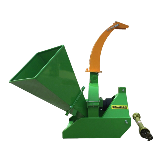
- Page 1 Wood Chipper Operator’s Manual BX42S & BX72R Please read this manual prior to operation...
- Page 2 IMPORTANT READ THESE INSTRUCTIONS BEFORE INSTALLING AND USING THIS IMPLEMENT...
- Page 3 INTRODUCTION Congratulations on your choice of a 3 Point Hitch Wood Chipper to compliment your operation. This equipment has been designed and manufactured to meet the needs of a discerning timber or landscaping industry. Safe, efficient and trouble free operation of your Wood Chipper requires that you and anyone else who will be using or maintaining the chipper, read and understand the Safety, Operation, Maintenance Trouble Shooting information contained within the Operator's Manual.
-
Page 4: Safety Alert Symbol
SAFETY SAFETY ALERT SYMBOL This Safety Alert symbol means The Safety Alert symbol identifies ATTENTION! BECOME ALERT! important safety messages on the YOUR SAFETY IS INVOLVED! TOWNSUNNY 3 Point Hitch Wood Chipper and in the manual. When you see this symbol, be alert to the possibility of personal injury or death. -
Page 5: General Safety
GENERAL SAFETY SAFETY 1. Read and understand the YOU are responsible for the SAFE operation and Operator’s Manual and maintenance of your TOWNSUNNY 3 Point Hitch all safety signs before Wood Chipper. YOU must ensure that you and using, maintaining, anyone else who is going to use, maintain or work adjusting or cleaning the around the 3 Point Hitch Wood Chipper be familiar... -
Page 6: Equipment Safety Guidelines
EQUIPMENT SAFETY GUIDELINES 1. Safety of the operator and bystanders is one 7. Never exceed the limits of a piece of of the main concerns in designing and machinery. If its ability to do a job, or to do so developing equipment. -
Page 7: Safety Training
SAFETY TRAINING SAFETY SIGNS 1. Safety is a primary concern in the design 1. Keep safety signs clean and legible at and manufacture of our products. all times. Unfortunately, our efforts to provide safe equipment can be wiped out by a single 2. -
Page 8: Maintenance Safety
PREPARATION MAINTENANCE SAFETY 1. Never use the machine until you have read 1. Good maintenance is your responsibility. and completely understand this manual, the Poor maintenance is an invitation to trouble. tractor Operator's Manual and each of the Safety Messages found on the safety signs on 2. - Page 9 2.7 OPERATING SAFETY 11. Use care when feeding material into chipper. Please remember it is important that you read Do not send metal, bottles, cans, rocks, glass and heed the safety signs on the 3 Point Hitch or other foreign material into wood chipper. If Wood Chipper.
-
Page 10: Hydraulic Safety
2.8 HYDRAULIC SAFETY 2.10 TRANSPORT SAFETY 1. Make sure that all the components in the hy- 1. Comply with state and local laws governing draulic system are kept in good condition and safety and transporting of machinery on are clean. public roads. -
Page 11: Safety Sign Locations
SAFETY SIGN LOCATIONS The types of safety signs and locations on the equipment are shown in the illustrations that follow. Good safety requires that you familiarize yourself with the various safety signs, the type of warning and the area, or particular function related to that area, that requires your SAFETY AWARENESS. •... - Page 12 The types of safety signs and locations on the equipment are shown in the illustrations that follow. Good safety requires that you familiarize yourself with the various safety signs, the type of warning and the area, or particular function related to that area, that requires your SAFETY AWARENESS. •...
- Page 13 The types of safety signs and locations on the equipment are shown in the illustrations that follow. Good safety requires that you familiarize yourself with the various safety signs, the type of warning and the area, or particular function related to that area, that requires your SAFETY AWARENESS. DANGER THROWN OBJECT HAZARD To prevent serious injury or death from...
- Page 14 The types of safety signs and locations on the equipment are shown in the illustrations that follow. Good safety requires that you familiarize yourself with the various safety signs, the type of warning and the area, or particular function related to that area, that requires your SAFETY AWARENESS. REMEMBER - If safety signs have been damaged, removed, become illegible or parts replaced without safety signs, new signs must be applied.
- Page 15 The types of safety signs and locations on the equipment are shown in the illustrations that follow. Good safety requires that you familiarize yourself with the various safety signs, the type of warning and the area, or particular function related to that area, that requires your SAFETY AWARENESS. REMEMBER - If safety signs have been damaged, removed, become illegible or parts replaced without safety signs, new signs must be applied.
- Page 16 The types of safety signs and locations on the equipment are shown in the illustrations that follow. Good safety requires that you familiarize yourself with the various safety signs, the type of warning and the area, or particular function related to that area, that requires your SAFETY AWARENESS. DANGER DANGER GUARDS MISSING...
- Page 17 ASSEMBLING The machine comes from the factory in a shipping configuration. Always use tools equipment and forklifts of appropriate size and capacity for the job. Always use 2 men when lifting, moving and assembling the machine. When the machine is shipped, follow this proce- dure when preparing for the customer: 1.
- Page 18 4. Cut the tie-down straps. Fig. 2 TIE-DOWNS 5. Lay-out components next to machine. BX32 BX62 Fig. 3 LAY-OUT...
- Page 19 6. Use a forklift to raise and lift the frame. Forklift 7. Or alternatively attach a lifting device to the lifting bracket on top of the frame. Bracket Fig. 4 LIFTING 8. Remove pallet and place machine on the ground. Fig.
- Page 20 9. Release feed hopper transport latch and lower hopper into the working position. Stow anchor latch. Fig. 6 HOPPER TRANSPORT LATCH 10. Tighten anchor bolts to their specified torque. Fig. 7 ANCHOR BOLTS (TYPICAL)
- Page 21 11. Connect the PTO drivline: a. Raise the input shaft guard. b. Check that the driveline telescopes eas-ily and that the shield rotates freely. c. Attach the driveline to the chipper input shaft by depressing the lock pin, slide yoke over the shaft and pushing on the yoke until the lock pin clicks into posi-tion.
-
Page 22: Operation
OPERATION OPERATING SAFETY • • Please remember it is important that you read Never use alcoholic beverages or drugs the operator's manual and heed the safety which can hinder alertness or coordination signs on the 3 Point Hitch Wood Chip-per. while operating this equipment. -
Page 23: Machine Components
5.2 MACHINE COMPONENTS The TOWNSUNNY 3 Point Hitch Wood Chipper is a rotor with blades for chip- ping wood. A hinged feed hopper moves the wood material into the rotor. Each rotor is designed with 4 blades and a twig-break- er to generate the small pieces of wood. -
Page 24: Machine Break-In
5.3 MACHINE BREAK-IN 5.4 PRE-OPERATION CHECKLIST Although there are no operational restrictions Efficient and safe operation of the TOWNSUNNY 3 on the Wood Chipper when used for the first Point Hitch Wood Chipper requires that each time, it is recommended that the following operator reads and understands the using proce- mechanical items be checked: dures and all related safety precautions outlined in... -
Page 25: Driveline Dimension
5. 5 DRIVELINE DIMENSION A PTO driveline is supplied with the machine. To ac- company the variety of 3 point hitch geometry available today, the driveline can be too long for most machines or too short for others. It is very important that the drive- line be free to telescope but not to bottom out when going through its working range. - Page 26 5.6 MOUNTING AND UNHOOKING TRACTOR When attaching chipper to a tractor, follow this procedure:. 1. Clear the area of bystanders, especially small children. 2. Make sure there is enough room and clear-ance to safely back up to the chipper. 3. Place the tractor arms in their full sway position.
- Page 27 5. Mounting with a Quick Hitch. a. Align the claws on the Quick Hitch slightly below the mounting pins on the chipper. IMPORTANT It may be necessary to add weight to the lower lift arms to bring them to the required height.
- Page 28 8. Connect the hydraulics: a. Use a clean rag or paper towel to clean the dirt from couplers on the hose ends and the tractor. b. Connect the hoses to the tractor cou- plers. Be sure the couplers are secure- ly seated.
- Page 29 5. 7 CONTROLS All controls are conveniently positioned next to where the operator would stand when feeding the machine to provide easy operation. Review this section to familiarize yourself with the loca- tion and function of each control before starting. 1.
- Page 30 Deflector Position: Each discharge hood is equipped with a deflector on the end to place the chips exactly where desired. There are 2 types available: a. Manual Clamp (BX42): The deflector is held in place by clamp- ing bolts on each side. Loosen the clamps, move the deflector and tighten the clamps.
-
Page 31: Field Operation
5. 8 FIELD OPERATION OPERATING SAFETY • • Please remember it is important that you Never use alcoholic beverages or drugs read the operator's manual and heed the which can hinder alertness or coordination safety signs on the 3 Point Hitch Wood while operating this equipment. - Page 32 4. Drive to the work area and position at the worksite. 5. Set park brake. 6. Stop engine. 7. Remove ignition key and place in your pocket. 8. Move the feed hopper down into its working configuration and secure with the anchor nuts. 9.
- Page 33 12. Emergency Stopping: Stop tractor engine if an emergency oc- curs. Correct emergency situation before starting engine and resuming work. 13. Feeding: a. Manual Feed: • Slowly slide the wooden material into the feed hopper and move it into the rotor.
- Page 34 16. Blades: There are 2 types of blades used on the Wood Chipper. They work together to cut, shear and shred the wood as it moves through the machine. a. Rotor blades: The rotor is equipped with 4 blades placed at 90° to each other to keep the rotor in balance.
- Page 35 18. Twig Breaker: Each machine is equipped with a twig breaker to break up twigs or other long material as it moves through the rotor compartment. Open the rotor cover and check the condition of the breaker on a weekly basis. Also check for any entangled material when the rotor cover is opened.
- Page 36 19. Shear Pin: The PTO driveline is designed with a shear pin at the input yoke to prevent overload-ing the drive system. Remove the broken parts from the yoke when the pin shears and replace with genuine TOWNSUNNY parts. The drive system is designed to function well without failing the shear pin.
-
Page 37: Severe Plug
20. Unplugging: Although the machine is designed to handle a wide variety of material without any prob- lem, occasionally it plugs. When the machine plugs, follow this procedure to unplug: a. Clear the area of bystanders, especially small children. Stop the engine, remove the ignition key and place it in your pocket and wait for all moving parts to stop before unplugging. - Page 38 21 . Cleaning: Clean the machine frequently to prevent a build- up of dust, chips and trash on the frame. A clean machine reduces the chance of rusting. Fig. 30 CLEANING 22. Curtains: Each feed hopper is designed with an internal rubber/belting curtain to prevent chips and de- bris from coming out of the hopper when work- ing.
- Page 39 23. Sharpening Blades: The rotor and stationary blades need to be sharp for the chipper to perform as expected. It is recommended that the rotor blades be removed from the rotor when sharpening. Always sharpen the blades at a 45° angle to provide the best cutting effect as it meets the stationary blade.
- Page 40 24. Hydraulic Feed Control: The machine with the hydraulic feed hop-per is designed with a control lever to place the hopper in FEED - OFF/NEUTRAL - RE- VERSE. Pull all the way out to feed, push in to the first detent for off or neutral and fully in for reverse.
-
Page 41: Personal Protective Equipment
25 . Personal Protective Equipment (PPE): Each person must wear appropriate personal protective equipment whenever operating the chipper or working in the vicinity. This equip- ment is designed to prevent injury to any personnel in the area. This list includes but is not limited to: •... -
Page 42: Transport Safety
5.9 TRANSPORTING TRANSPORT SAFETY 1. Comply with state and local laws govern- 5. Be sure the trailer is hitched positively to ing safety and transporting of machinery the towing vehicle and a retainer is used on public roads. through the mounting pins. 6. -
Page 43: Placing In Storage
5. 10 STORAGE 3. Inspect all rotating parts for entangled mate- OPERATING SAFETY rial. Remove all entangled material. 4. Run the machine a few minutes to dry • Store the unit in an area away from human the moisture from inside the machine. activity. -
Page 44: Service And Maintenance
6 SERVICE AND MAINTENANCE 6.1 SERVICE MAINTENANCE SAFETY 6.1 .1 FLUIDS AND LUBRICANTS • Good maintenance is your responsibility. 1. Grease: Poor maintenance is an invitation to trouble. Use an SAE multipurpose high temperature grease with extreme pressure (EP) • Follow good shop practices. perform-ance. -
Page 45: Servicing Intervals
6.1 .3 SERVICING INTERVALS The period recommended is based on normal operating conditions. Severe or unusual cond- tions may require more frequent lubrication or oil changes. Hours or Daily 1. Grease PTO driveline. Fig. 38 PTO driveline 40 Hours or Weekly 1. - Page 46 3. Check sharpness of blades: Rotor Stationary Remove, sharpen or switch edge as required. BX32 Rotor Stationary Fig. 41 BLADES 100 Hours 1. Grease the hydraulic feed system: Roller bearings. Pivot bushing. Left Side Right Side Fig. 42 HYDRAULIC FEED SYSTEM...
- Page 47 100 Hours 2. Grease rotor bearings on BX42 and BX62 models. IMPORTANT Do not over grease. Front WARNING Machine is shown with guard re- moved or rotor cover opened for illustrative purposes only. Do not operate machine with guard removed or cover opened. Rear Fig.
- Page 48 Annually 1. Clean machine. BX32 BX42 BX62 Fig. 45 MACHINE...
-
Page 49: Driveline Maintenance
6.2 MAINTENANCE By following a careful service and maintenance program for your machine, you will enjoy many years or trouble-free operation. 6.2.1 DRIVELINE MAINTENANCE driveline should telescope easily and the guard The PTO driveline is designed to telescope to al-low turn freely on the shaft at all times. - Page 50 6.2.2 DRIVE BELT TENSION AND ALIGNMENT (Model BX32) A set of V belts transmits rotational power to the rotor. They must be kept properly tensioned and the pulleys aligned to obtain the expected perfor- mance and life. To check the tension and alignment, follow this procedure: Clear the area of bystanders, especially small children.
-
Page 51: Specifications
Discharge Hood Rotation Discharge Hood Height 58" 60" 74" Rated RPM 540-1000 540-1000 Weight 320 lbs BX42S -425lbs/BX42R-625lbs BX62S-770lbs/BX62R-1070lbs BX92 Drive System Direct drive, pto w/shearbolt Engine Chipper capacity 10" diameter, (up to 14" slab) Chipper Housing Opening 10 1/2" x 14"... -
Page 52: Bolt Torque
7.2 BOLT TORQUE CHECKING BOLT TORQUE The tables shown below give correct torque values for various bolts and capscrews. Tighten all bolts to the torques specified in chart unless otherwise noted. Check tightness of bolts periodically, using bolt torque chart as a guide. Replace hardware with the same strength bolt. ENGLISH TORQUE SPECIFICATIONS Bolt Torque* Bolt... -
Page 53: Hydraulic Fitting Torque
7.3 HYDRAULIC FITTING TORQUE Tightening Flare Type Tube Fittings 1. Check flare and flare seat for defects that might cause leakage. 2. Align tube with fitting before tighten- ing. 3. Lubricate connection and hand tighten swivel nut until snug. 4. To prevent twisting the tube(s), use two wrenches. Place one wrench on the connector body and with the second tighten the swivel nut to the torque shown. - Page 54 BX42S Wood Chipper...
- Page 55 Ser.No. Part No. Name & Specification Qty Remarks BX42S.103 Guiding Cap 出料口罩 BX42S.114 Knob 把手螺母 BX42S.016 Discharge Chute 出料口焊合件 HBF6A35 Bolt M6*35 螺栓 M6*35 Plain Washer 6 平垫 6 Nylon Nut M6 锁紧螺母 M6 HBF6A30 Bolt M6*30 螺栓 M6*30 BX42S.018 Hood Latch 锁座焊合件...
- Page 56 BX42S wood chipper SW14 Plain Washer 14 弹垫 14 HB14A1.5A35 Bolt M14*15*35 螺栓 M14*1.5*35 EFH175-105 Lower Pin 下悬挂销 PW24 Plain Washer 24 平垫 24 NN24 Nylon Nut M8 锁紧螺母 M24 BX42S.106 Base 橡胶挡板 HN24 Nut M8 六角螺母 M8 HBF8A30 Bolt M8*30 螺栓...
- Page 57 BX72R...
- Page 58 Part No. old Part No Name & Specification 02.BX72.01.001 BX62-015 output chute hat 02.BX72.01.002 BX62-114 spring 02.BX72.01.003 M10 nut with hat 02.BX72.01.004 #3 chain 1230mm 02.BX72.01.005 BX62-016 03.01.5782.M6x35 hexagon head bolt M6x35 03.03.97,1.Φ8 flat washer Φ8 03.02.6182.M6 locking nut M6 02.BX72.01.009 BX42-018 handle...
- Page 59 Part No. old Part No Name & Specification 03.16.5860.G1/2 quick release coupling G1/2 03.18.982.G1/2 washer G1/2 oil pipe, 3200mm Φ22.5 02.BX72.02.003 BX62-125 oil pipe, 780mm Φ22.5 02.BX72.02.004 BX62-127 02.BX72.02.005 BX62-118 adapter oil pipe, 1600mm Φ22.5 02.BX72.02.006 BX72-116 02.BX72.02.007 hydraulic motor BMP200 oil pipe, 1500mm Φ22.5 02.BX72.02.008 BX72-115...
- Page 60 Part No. old Part No Name & Specification 02.BX72.03.001 BX72-016 lower roller cover 1 03.07.DIN11023.Φ56 linch pin 02.BX72.03.003 BX72-022 lower roller 03.05.7809.UCP208 inserted bearing with housing UCP208 03.01.77.M6x20 Hexagon socket set screws with falt point 02.BX72.03.006 BX72-015 lower roller cover 2 02.BX72.03.007 BX72-021 upper roller...
- Page 61 02.BX72.03.017 BX72-014 feeding chute 03.01.5783.M10x30 full thread hexagon head bolt M10x30 02.BX72.03.019 BX72-118 rubber plate 03.02.6182.M10 locking nut M10 02.BX72.03.021 rubber plate 03.08.894,1.Φ35 circlip for shaft 35 02.BX72.03.023 BX72-105 spring 02.BX72.03.024 BX72-113 right plate of foldable chute 02.BX72.03.025 BX72-027 handle 02.BX72.03.026 BX72-026 bottom plate...
- Page 62 03.05.7809.UCP208 inserted bearing with housing UCP208 03.02.6182.M14 locking nut M14...
- Page 63 Part No. old Part No Name & Specification 03.01.5783.M12x35 full thread hexagon head bolt M12x35 02.BX72.04.002 BX72-011 upper housing 03.02.6182.M12 locking nut M12 03.02.6182.M10 locking nut M10 02.BX72.04.005 BX72-102 rotor knife hexagon socket countersunk head cap 03.01.70,3.M10x35 screws M10x35 03.05.7809.UCF210 inserted bearing with housing UCF210 03.03.97,1.Φ14 flat washer Φ14...
- Page 64 The complete unit or parts should be returned to Victory Tractor Implements. The customer may have to cover the return shipping expense and is responsible for avoiding damage from the transport.
Need help?
Do you have a question about the BX42S and is the answer not in the manual?
Questions and answers