Canon iP4300 Simplified Service Manual
Hide thumbs
Also See for iP4300:
- Quick start manual (436 pages) ,
- Brochure & specs (4 pages) ,
- Start here (2 pages)
Table of Contents
Advertisement
Quick Links
iP4300
SIMPLIFIED SERVICE MANUAL
1. PRODUCT LIST
2. PRODUCT SPECIFICATIONS
3. ERROR DISPLAY
4. REPAIR
5. SERVICE MODE
6. EXTERNAL VIEW / PARTS LIST
7. TROUBLESHOOTING FLOWCHART
8. SPECIAL NOTES ON SERVICING
9. PRODUCT TECHNICAL INFORMATION
APPENDIX 1: SERVICE TEST PRINT
APPENDIX 2: EEPROM INFORMATION PRINT
QY8-13BA-000
Rev. 00
July 25, 2006
Canon Inc.
1
Advertisement
Table of Contents

Related Manuals for Canon iP4300


Summary of Contents for Canon iP4300
- Page 1 SIMPLIFIED SERVICE MANUAL 1. PRODUCT LIST 2. PRODUCT SPECIFICATIONS 3. ERROR DISPLAY 4. REPAIR 5. SERVICE MODE 6. EXTERNAL VIEW / PARTS LIST 7. TROUBLESHOOTING FLOWCHART 8. SPECIAL NOTES ON SERVICING 9. PRODUCT TECHNICAL INFORMATION APPENDIX 1: SERVICE TEST PRINT...
-
Page 2: Product List
1. PRODUCT LIST 1-1. Main Units Production q'ty Product name Product code Destination Accessories (for 3 months) Print head Canon Inkjet Printer Q30-4210-000 1438B001AA 194,000 Ink tanks iP4300 Q30-4213-000 1438B002AA 49,000 (Japan / Non-Japan) Q30-4210-000 1438B003AA BCI-9BK / PGI-5BK BCI- 7eBK / CLI-8BK... -
Page 3: Product Specifications
When printing a 6 megapixel image taken by certain Canon digital camera from PictBridge on default settings using Photo Paper Plus Glossy without border. -
Page 4: Product Life
Paper Same as the ASF, except that the Legal and Credit Card sizes and Photo Stickers specifications cannot be used in the cassette. DVD / CD print Supported media CD / DVD printable media Media size 120 mm / 80 mm (diameter) Print operation Front loading... -
Page 5: Print Head Specifications
Color document: Declared yield value in accordance with ISO/IEC FCD24711. Values obtained by continuous printing. "Photo (4"" x 6""): When printing Canon standard patterns on 4"" x 6"" <Photo Paper Plus Glossy> continuously with the default settings of <Photo Paper Plus Glossy>... -
Page 6: Error Display
3. ERROR DISPLAY Errors are indicated by the LED, and warnings are displayed on the monitor of the computer connected to the printer. 3-1. Operator Call Errors (Alarm LED Blinking in Orange) Alarm LED blinking in Error [Error code] Solution Remarks orange 2 times... - Page 7 (Operator Call Errors cont'd) Alarm LED blinking in Error [Error code] Solution Remarks orange 6 times Inner cover open. [1841] Close the inner cover, and press the Resume/Cancel button. Inner cover open during Close the inner cover, and press the printing on paper.
- Page 8 (Operator Call Errors cont'd) Alarm LED blinking in Error [Error code] Solution Remarks orange 13 times The remaining ink amount Replace the applicable ink tank with a The error is indicated when raw unknown. [1683] new one, and close the top cover. ink is detected but the dot count Printing with a once-empty ink tank can number exceeds the threshold of...
- Page 9 3-2. Service Call Errors (by Cyclic Blinking in Orange (Alarm LED) and Green (Power LED), or Alarm LED Lit in Orange) Solution Cycles of blinking in Error [Error code] (Replacement of listed parts, which are likely to be orange and green faulty) 2 times Carriage error [5100]...
- Page 10 3-3. Warnings (1) Printer (no LED indications) Displayed warning Remarks Low ink Status indication only. Print head temperature rise If the print head temperature is high when the access cover is opened, the warning is displayed When the print head temperature falls, the warning is released. Protection of excess rise of the print head If the print head temperature exceeds the specified limit, a Wait is temperature...
- Page 11 4. REPAIR 4-1. Notes on Service Part Replacement (and Disassembling / Reassembling) Service part Notes on replacement Adjustment / settings Operation check After replacement: Logic board ass'y - Before removal of the logic board - EEPROM QM3-1266 ass'y, remove the power cord, and 1.
-
Page 12: Grease Application
General notes: - Make sure that the flexible cables and wires in the harness are in the proper position and connected correctly. - Do not drop the ferrite core, which may cause damage. - Protect electrical parts from damage due to static electricity. - Before removing a unit, after removing the power cord, allow the printer to sit for approx. -
Page 14: Paper Feed Motor Adjustment
4-3. Paper Feed Motor Adjustment Perform the following adjustments when the paper feed motor unit is replaced: When attaching the motor, fasten the screws so that the belt is properly stretched (in the direction indicated by the blue arrow in the figure below). After replacement, be sure to perform the service test print, and confirm that no strange noise or faulty print operation (due to dislocation of the belt or gear, or out-of-phase motor, etc.) occurs. -
Page 15: Service Mode
5. SERVICE MODE Function Procedures Remarks Set a sheet of A4 or letter size paper in Service test print See "Service mode operation - Model name procedures" below. the ASF . - Destination For print sample, see APPENDIX 1, - ROM version SERVICE TEST PRINT. - Page 16 Time(s) LED indication Function Remarks 0 times Green (Power) Power off When the print head is not installed, the carriage returns and locks in the home position capped. 1 time Orange (Alarm) Service test print See APPENDIX 1, SERVICE TEST PRINT.
- Page 17 3 times HP BrightWhite 4 times Canon Extra, STEINBEIS Note: - Each time the Resume/Cancel button is pressed, the Alarm and Power LEDs light alternately, Alarm in orange and Power in green. - If the Resume/Cancel button is NOT pressed, and only the Power button is pressed, the printer remains in the LF correction mode.
- Page 18 In the printout, select the Pattern No. in which streaks or lines are the least noticeable, press the Resume/Cancel button the same number of time(s) as the selected Pattern No., then press the Power button. 3-1) LF correction value Selected pattern number Number of times the Resume/Cancel button is pressed 1 time 0 times...
- Page 19 From each paper source (ASF and cassette), 2 sheets of paper are ejected. The first sheet is blank, and the left margin correction pattern is printed on the second sheet. Printing sequence: For detail, see the flowcharts below. A sheet of paper feeds from the ASF, and ejected blank (single-sided printing). A sheet of paper feeds from the ASF.
- Page 20 Left margin correction START Start of duplex printing from the Press the Resume/Cancel button ASF and cassette (key entry) "L" times, then press the Power button to fix the selection. L = 0 No (N >= 2) L = 1 Printing is performed according to the current correction values in the Duplex printing from the...
- Page 21 Duplex printing from the ASF and cassette START Paper source: Paper type: Plain paper Print quality: Standard (Custom 3) Single-sided printing Print data: No data (blank) Print quantity: 1 sheet (1 page) Paper source: Paper type: Plain paper Print quality: Standard (Custom 3) Duplex printing Print data:...
-
Page 22: External View / Parts List
(For the print head, the YFI will be made in the 5th year after discontinuance of production.) Stock Date SENSO Parts, Starter Parts: From August 25, 2006 Other parts: From November 27, 2006 Repair by Canon Inc. Not available. (No repair is conducted by Canon Inc.) - Page 23 FIGURE 1 PRINTER & PRINT HEAD...
- Page 24 FIGURE & PART NUMBER RANK QTY DESCRIPTION REMARKS KEY No. QM2-3892-000 CASSETTE UNIT QC2-1925-000 COVER, CASSETTE QA4-1117-000 TRAY, CD SUB W/ CDR PRINTING QL2-1449-000 CDR TRAY ASS'Y W/ CDR PRINTING QY6-0061-000 PRINT HEAD QK1-0278-000 CORD, POWER 100V-120V(US, CA) QK1-0279-000 CORD, POWER 220V-240V(EUM, EMB, ASA) QK1-0286-000 CORD, POWER...
- Page 25 FIGURE 2 AC ADAPTER...
- Page 26 FIGURE & PART NUMBER RANK QTY DESCRIPTION REMARKS KEY No. QK1-3031-000 AC ADAPTER: 100V-240V 50/60HZ...
- Page 27 FIGURE 3 OPERATION PANEL UNIT & MAIN CASE UNIT...
- Page 28 FIGURE & PART NUMBER RANK QTY DESCRIPTION REMARKS KEY No. QM3-0450-000 PAPER SUPPORT UNIT QC2-2901-000 EMBLEM, PIXMA QC2-2902-000 EMBLEM, PIXUS QM3-0447-000 ACCESS COVER UNIT QM3-0445-000 PANEL COVER R UNIT QM3-0448-000 SIDE COVER R UNIT QC2-1844-000 SIDE COVER L UNIT QC2-1827-000 MAIN CASE UNIT QC2-1826-000 COVER, I/F...
- Page 29 FIGURE 4 BOTTOM CASE UNIT & INK ABSORBER...
- Page 30 FIGURE & PART NUMBER RANK QTY DESCRIPTION REMARKS KEY No. QY5-0176-000 ABSORBER KIT QM3-0446-000 BOTTOM CASE UNIT...
- Page 31 FIGURE 5 LOGIC BOARD ASS'Y...
- Page 32 FIGURE & PART NUMBER RANK QTY DESCRIPTION REMARKS KEY No. QM3-1266-000 LOGIC BOARD ASS'Y...
- Page 33 FIGURE 6 SHEET FEED UNIT...
- Page 34 FIGURE & PART NUMBER RANK QTY DESCRIPTION REMARKS KEY No. QM3-1292-000 DC CONNECTOR ASS'Y QM3-1287-000 MOTOR MULTI HARNESS ASS'Y QM3-1284-000 SENSOR MULTI HARNESS ASS'Y QC1-9982-000 COVER, PAPER FEED GUIDE QM2-3894-000 SHEET FEED UNIT...
- Page 35 FIGURE 7 CARRIAGE UNIT...
- Page 36 FIGURE & PART NUMBER RANK QTY DESCRIPTION REMARKS KEY No. QC1-6526-000 FILM, TIMING SLIT STRIP QC2-0010-000 CAM, CARRIAGE SHAFT R QK1-1500-000 MOTOR, CARRIAGE QC2-0009-000 CAM, CARRIAGE SHAFT L QM2-3884-000 CARRIAGE UNIT QL2-0938-000 IDLER PULLEY ASS'Y...
- Page 37 FIGURE 8 PLATEN UNIT...
- Page 38 FIGURE & PART NUMBER RANK QTY DESCRIPTION REMARKS KEY No. QC2-0435-000 ABSORBER, INK QM3-0001-000 PLATEN UNIT QC1-6619-000 SPRING, TORSION...
- Page 39 FIGURE 9 PURGE UNIT...
- Page 40 FIGURE & PART NUMBER RANK QTY DESCRIPTION REMARKS KEY No. QK1-3018-000 CABLE, PANEL QM3-0033-000 PURGE UNIT QC2-0032-000 TUBE, INK QC2-0030-000 COVER, INK TUBE QC2-0085-000 TUBE, INK JOINT...
- Page 41 FIGURE 10 PAPER FEED & CARRIAGE LIFT PART...
- Page 42 FIGURE & PART NUMBER RANK QTY DESCRIPTION REMARKS KEY No. QC1-9941-000 CAM, SWING ARM LOCK QL2-1450-000 PR LIFT SHAFT ASS'Y QM2-3890-000 PAPER GUIDE UNIT QM2-3886-000 PRESSURE ROLLER ASS'Y QM3-1273-000 CARRIAGE LIFT SENSOR UNIT QC2-0037-000 CARRIAGE LIFT GEAR BASE UNIT QC2-1873-000 GEAR, INPUT CARRIAGE LIFT QC1-6212-000...
- Page 43 FIGURE 11 OPTION & CONSUMABLES...
- Page 44 FIGURE & PART NUMBER RANK QTY DESCRIPTION REMARKS KEY No. 11 - BLACK INK TANK BCI-9BK CONSUMABLES BLACK INK TANK BCI-7eBK CONSUMABLES YELLOW INK TANK BCI7eY CONSUMABLES MAGENTA INK TANK BCI-7eM CONSUMABLES CYAN INK TANK BCI-7eC CONSUMABLES BLACK INK TANK PGI-5BK CONSUMABLES BLACK INK TANK CLI-8BK CONSUMABLES...
- Page 45 FIGURE 12 TOOL...
- Page 46 FIGURE & PART NUMBER RANK QTY DESCRIPTION REMARKS KEY No. QY9-0057-000 LUBE, FLOIL KG107A, OIL...
-
Page 47: Screw & Washer List
SCREW & WASHER LIST FIGURE & PART NUMBER RANK QTY DESCRIPTION REMARKS KEY No. XB1-2300-405 SCREW, MACH.BH, M3X4 XA9-1258-000 SCREW, TAP, WASHER HEAD, M3X12 XB2-4300-605 SCREW, W/WASHER, M3X6 XB4-7300-805 SCREW, TP, BH3X8 XA9-1437-000 SCREW, BIND, M2.6X4(RED) XB1-2200-405 SCREW, M2X4... -
Page 48: Troubleshooting Flowchart
7. TROUBLESHOOTING FLOWCHART 7-1. Printer Main Unit Troubleshooting Flowchart (how to confirm printer operation at refurbishment) Refer to 5. SERVICE MODE Power ON in the for printing method. service mode Service Call Error? Open access cover, and install print head Service Call Error? <Service test print check items>... - Page 49 *1: Refurbishment completion procedures: At end of refurbishment of normal printers, set the printer to the default shipment conditions (with the carriage locked in the home position, and the paper lifting plate in the raised position), following the steps below. Install the print head, and while pressing and holding the Power button, connect the AC plug.
- Page 50 7-2. Print Head Troubleshooting Flowchart (print head operation confirmation) Connect to printer Nozzle check pattern printing Correct? Print head cleaning Nozzle check pattern printing Correct? Print head deep cleaning Nozzle check pattern printing Correct? Print head deep cleaning Nozzle check pattern printing Correct? Replace ink tanks Nozzle check pattern printing...
-
Page 51: Special Notes On Servicing
8. SPECIAL NOTES ON SERVICING This section describes the procedures for transporting the printer for returning after repair, etc. In the service mode, press the Power button to finish the mode, and confirm that the paper lifting plate of the sheet feed unit is raised. Keep the print head and ink tanks installed in the carriage. - Page 52 9. PRODUCT TECHNICAL INFORMATION 9-1. FAQ (Problems specific to the iP4300 and corrective actions) No. Rank Function Phenomenon Condition Cause Corrective action Possible call or complaint Paper Paper feeding problems - Low temperature and low Due to curl of a round-trip postcard in - Eliminate the curl of the - Paper jams.
- Page 53 (9-1. FAQ cont'd) No. Rank Function Phenomenon Condition Cause Corrective action Possible call or complaint Print Soiling on paper in - Automatic duplex printing (Photo On the rib(s) inside the sheet feed unit Temporary operational - Paper gets smeared. results automatic duplex printing Paper Plus Double Sided, used for duplex printing, ink mist may...
- Page 54 (9-1. FAQ cont'd) No. Rank Function Phenomenon Condition Cause Corrective action Possible call or complaint Print Soiling on paper The printer has been used for a Due to ink mist attached to the ASF Clean the ASF sub-rollers (see *3 results long period of time with the ASF sub-pick-up rollers.
- Page 55 Fold the paper at approx. 60 mm from the end, and fold the folded end in half backward, as shown below. Moisten the folded end portion (indicated by the blue circle in the figure below) using a wipe, and set the paper in the ASF so that the moistened edge of the paper contacts the 2 sub-rollers.
-
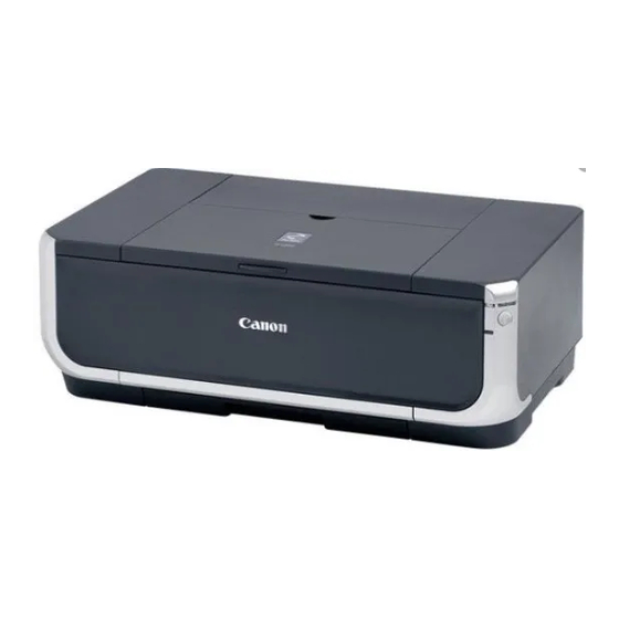
Page 56: New Technologies
Americas. (2) Design With the silver frame holding the main body from the bottom, the iP4300 wears a stately look in a fresh design. The square form makes the printer look more compact and shorter in height. - Page 57 By pressing and holding the Resume/Cancel button for 5 seconds or longer, the function to detect the remaining ink amount can be disabled. Unknown: Raw ink remains, but the dot count value exceeds the threshold of complete exhaustion of ink. By pressing and holding the Resume/Cancel button for 5 seconds or longer, the function to detect the remaining ink amount can be disabled.
-
Page 58: Appendix 1: Service Test Print
APPENDIX 1: SERVICE TEST PRINT <EEPROM information contents> On the service test print (sample below), confirm the EEPROM information as shown below. Top area: iP4300: Model name Vx.xx: ROM version D = xxx.x: Ink absorber counter value (%) USB (xxxxxx):... - Page 59 <Service test print sample> Check 1 Check 2 Check 3 Check 4 Check 5 Check 6 Check 7 Check 8 Check 9 Check 10 Check 2 Check 11...
-
Page 60: Appendix 2: Eeprom Information Print
19. User print head alignment values (BKoe/Coe/SCoe//CLbi/SCLbi/C-SC/BK-CL/BKbiPP/CLbiPP/SCLbiPP/NZctr/NZedge/CLbiHiReso/ SCLbiHiReso) 20. Camera Direct Print-supported device connection record (PB = Canon PictBridge-supported camera, OPB = Other PictBridge-supported camera) 21. ASF feed pages (total, plain paper, High Resolution Paper & Matte Photo Paper, Photo Paper Pro &... - Page 61 postcard, envelope) 23. Auto duplex print pages (total, Photo Paper Plus Double Sided, postcard) 24. Camera Direct print pages (total) 25. Borderless print pages (total) 26. 4x6 print pages 27. Number of CDs and DVDs printed 28. CD / DVD print position adjustment value 29. CD / DVD sensor correction value 30.
Need help?
Do you have a question about the iP4300 and is the answer not in the manual?
Questions and answers