Advertisement
Quick Links
Published Manual Number/ECN: MPIMWTXXAE/2019082A
• Publishing System: TPAS2
• Access date: 02/18/2019
• Document ECNs: Latest
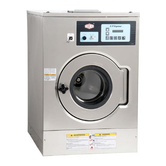
Installation and Service
MCT12E5, 16E5, 18E4
MWT12E5, 12X5, 12J5
MWT16E5, 16X5, 16J5
MWT18E4, 18X4, 18J6
PELLERIN MILNOR CORPORATION
POST OFFICE BOX 400, KENNER, LOUISIANA 70063-0400, U.S.A.
Advertisement


Need help?
Do you have a question about the MCT12E5 and is the answer not in the manual?
Questions and answers