Advertisement
Available languages
Available languages
Quick Links
All manuals and user guides at all-guides.com
D D IGITA
AL WIR
RELESS
DIGITA
TALES K
KABELL
SYSTE
EME D
DIGIT
TALE D
DRAAD
with 10,9
w
S BACK
K‐UP CA
LOSES
SYSTE
EM
E CAM
MERA D
DE REC
NU
UMERIQ
QUE
LOOS
9cm / 4.3
3" monit
mit 10,9
cm / 4,3
avec écr
ran 10,9c
m
met 10,9
9cm / 4,3
3" monito
DRC434
40
AMERA
A SYST
RÜCK
FAHRK
KAMER
CUL SA
ANS FIL
CAME
ERASYS
STEEM
tor
" Monito
or
cm / 4,3"
"
or
TEM
RA‐
L
M
Advertisement

Related Manuals for pro user DRC4340


Summary of Contents for pro user DRC4340
- Page 1 All manuals and user guides at all-guides.com D D IGITA AL WIR RELESS S BACK K‐UP CA AMERA A SYST TEM DIGITA TALES K KABELL LOSES RÜCK FAHRK KAMER RA‐ SYSTE EM SYSTE EME D E CAM MERA D DE REC CUL SA ANS FIL L UMERIQ QUE DIGIT TALE D DRAAD LOOS ...
-
Page 2: Important Safety Instructions
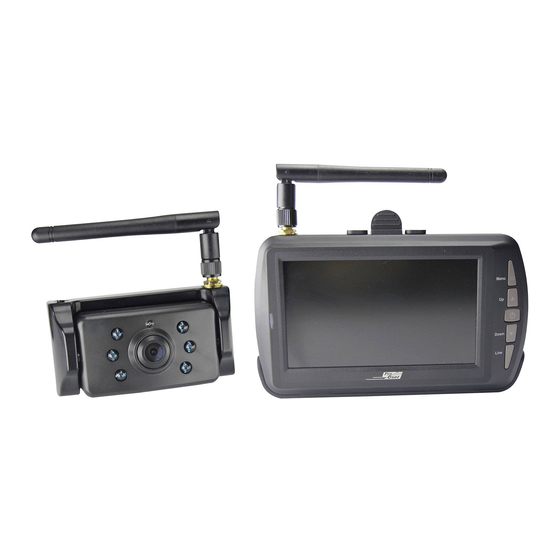
All manuals and user guides at all-guides.com INTRODUCTION The Pro‐User DRC4340 is a member of the family of advanced car back‐up systems manufactured by Pro User International Ltd. The Pro‐User Digital Back‐up Camera and Monitor with built in transmitter box, when used as described, will improve your ability to see behind your car, camper, trailer, or mini‐van. We have taken numerous measures in quality control to ensure that your product arrives in top condition, and will perform to your satisfaction. Please carefully read and follow the following safety and operating instructions. IMPORTANT SAFETY INSTRUCTIONS Before You Install If you are not confident working with 12V/24V DC vehicle wiring, removing and reinstalling interior panels, carpeting, dashboards or other components of your vehicle, contact the vehicle’s manufacturer, or consider having the camera system professionally installed. Innovation :NO Interference This device is free from interferences coming from Bluetooth, cell phones, Wi‐FI routers, power lines and other various electrical equipment. Repair The camera system should not be opened. Any attempt at modification or repair by the user will entail the loss of your guarantee. PARTS 1. Monitor and mounting Arm 2. Camera with mounting plate ... -
Page 3: Installation
All manuals and user guides at all-guides.com 3. Metal bracket 4. Mounting Accessories ... - Page 4 All manuals and user guides at all-guides.com Bracket for Numberpla ate A1. Remove e the rear lic cense plate, , and then l oosen the l icense plate e bolts/scre ews. A2. Position the supplie ed mountin g plates (wi ith camera together) b behind the l icense plate e bracket. Secure both license pla ate bracket a and mounti ing plates w with the lice ense plate b bracket bolt s/screws. A3. Mount t the license p plate on the...
- Page 5 All manuals and user guides at all-guides.com B2. Installing the second part of metal bracket to cars, then assembling the two parts of metal bracket as below: After chosing camera model A or B please go ahead with the following installation steps: 1. Choose a routing path for the camera’s power cable through the vehicle’s body to the reverse light circuit. If in doubt, seek professional installation assistance. 2. Some vehicles may have a hole available to pass the wire through, such as where the license plate light is mounted, or you can drill a hole close to where the power cable is attached to the camera. Once you have chosen where the cable will enter the vehicle’s body, remove the camera. If you are able to use an existing opening, skip ...
- Page 6 All manuals and user guides at all-guides.com the next two steps. 3. Before you drill a hole you MUST CHECK and see WHAT IS BEHIND WHERE YOU ARE DRILLING. If there are any vehicle components, such as electrical parts or fuel system components behind where you are drilling, you must take whatever precaution is necessary not to damage them. Remove the license plate and camera before drilling. 4. After you have drilled the hole, insert the supplied grommet, then pass the camera cables through the grommet into the vehicle. You must use the grommet to prevent the metal edge of the hole from cutting the camera cable. 5. Next you’ll need to find the vehicle’s reverse lights. Turn the vehicle’s ignition key to the accessory position, engage the parking brake and put the car in reverse. Look at the vehicle’s tail lights to see where the reverse lights are located, they are the white lights. To locate the reverse light’s 12V/24V + wire it will be necessary to gain access to the rear of the vehicle’s tail light. For help locating the vehicle’s reverse light circuit contact your vehicle’s manufacturer for vehicle specific wiring diagrams. 6. Once you have located the reverse light circuit you will have to route the camera cable to that location. You must securely fasten the power cable to prevent it from being caught on any vehicle component such as the trunk hinge. Never route the cable on the outside of the vehicle! 7. The reverse light sockets on most vehicles have two wires connected to them. Usually the negative wire is black and the positive wire is a colored wire. If you are uncertain about the ...
- Page 7 All manuals and user guides at all-guides.com 8. After determining which wire is the positive and which is the negative, turn off the ignition key, then remove the battery’s negative cable. 9. Splice the red wire using the supplied in‐line wire connectors to the reverse light’s Positive (+) wire. Use a set of slip joint pliers to squeeze the TAP and insure good Connection. 10. Next splice the black wire of the camera power cable to the reverse light’s negative (‐) wire or ground. 11. Replace the reverse light bulb, and then re‐install the light socket. Secure all the wires with cable ties or electrical tape. 12. Re‐attach the negative battery cable to the battery. Monitor Installation When choosing a location to mount the monitor, make sure the monitor is in an area that will not obstruct your vision while driving. 1. Before mounting the monitor, clean the mounting surface well. 2. Position the suction mount to the smooth surface which suits your requirement. 3. Press the suction cap against the smooth surface and press the lock down to attach and fix the mount to the surface. ...
- Page 8 All manuals and user guides at all-guides.com 5. Route th he power ca able to the v vehicle’s cig garette light ter socket 1 12V/24V po ower outlet. The cabl le must not interfere w with the safe e operation n of the veh icle. 6. Insert th he small 12V V/24V DC pl lug of the p power cable into the rig ght side of t the monitor r. 7.
-
Page 9: Operation
All manuals and user guides at all-guides.com OPERATION Operation and signal instructions of the product (Describe the steps and instructions in details, including error description) 1. Power supply Power of the receiver is supplied with socket of car‐borne cigarette lighter 12V or DC24V DC. 2. Operation of Receiver: a. After power is on, the blue indicator is on and the receiver enters working state automatically. b. If there is no signal, LCD of the receiver turns off automatically, and blue LED indicator flashes; when there is any signal, the image is displayed, and the LED is on. c. Description of receiver buttons. The buttons include Menu/Return, Up/Channel Selection, Power/Confirm, Down, and Guideline, as shown in the figure below: Menu Press to show OSD or return to the previous menu Up Select forward in OSD operation Power Confirm or enter in OSD operation,Press and turn off/on when there is no OSD Down Select backward in OSD operation Line Guideline display selection ... - Page 10 All manuals and user guides at all-guides.com 3. Pairing Press MENU U button to enter main menu, and d press Conf firm key to enter pairin ng interface e. Press Confir rm key to en nter pairing state, whe en PAIRING appears. At this time please pres ss the butto on at the ca mera in ord der to pair t the camera with the m onitor. After pairing g is successf ful, there w will be show ...
- Page 11 All manuals and user guides at all-guides.com 4. SETUP Press UP or Down butto on to select t “ SETUP” t to enter bel low screen. 4.1. AUTO O DISPLAY Press confirm m key to se elect the cam mera CAM1 1、CAM2、 or SPLIT. 4.2. MIRR ROR Select MIRR ROR to ente r below the eme, NORM MAL/UP/FLIP P/UP&FLIP, Then Press confirm Ke e y. ...
- Page 12 All manuals and user guides at all-guides.com 4.3. Vers ion Select VERSI ION, Press C Confirm Key y to enter a and view sof ftware vers ion informa ation of the eceiver and d transmitte er. n view VERS SION inform mation scree en, Press th he “UP” key y for 5s to cl ear paired c channels. Please use t his function n carefully, two paired channels w will be cleare ed at the sa ame time,an...
- Page 13 All manuals and user guides at all-guides.com 4.6. TRAST sett ing Select icon o of contrast, press Conf irm key to e enter, and p press Up an d Down key y to select a an Appropriate e display eff fect. 4.7. COLO OR setting Select incon n of color, p ress Confirm m key to en nter, press U Up and Dow wn key to se elect an app ropriate Display effec ct. ...
- Page 14 All manuals and user guides at all-guides.com 4.8. Other operation. 4.8.1. Press”Up” Key to enter Auto display when there is no OSO. 4.8.2. Press “DOWN” to select CAM1/CAM2/CAM1&CAM2 when there is no OSO. 5. Camera transmitter operation : 5.1. The camera transmitter is installed in the rear side of the car when it is used for backing, please connect to power supply of taillights; if it is installed in the car for door monitoring, it can be connected to power supply of interior lights, or other 8V‐30V DC power supply systems. When it is connected to power cord in parallel, be cautious that red wire is +, and black wire is ‐. Prevent from short circuit and take insulation measures, for electrical short circuit may result in fire or other serious consequences. Camera transmitter features anti‐reversing connection, and the device won' t be damaged in the event of reverse connection. 5.2. When it is used for the first time, be sure to pair with the receiver. Select CAM1 or CAM2 channel for the receiver, press Confirm key to enter pairing mode, and then press PAIR key within 30S, wait for pairing to be completed, ensure that wireless signal isn' t interfered with in the pairing process, and icon of PAIRED will be displayed on the receiver after pairing is successful. If the pairing isn' t completed in time, it will return to the previous state. For an installed device, the pairing requires two persons for operation. 5.3. One camera transmitter can only be paired with one channel. The receiver has two channels, which can be paired with one camera transmitter separately or with two ...
- Page 15 All manuals and user guides at all-guides.com 6.3. Connect one end of power cord of the receiver to the host and plug the other end directly into the socket of car‐borne cigarette lighter. 6.4. The transmitter can be mounted on rear of the car for car backing monitoring, or in the car where it can be fixed securely. ...
- Page 16 All manuals and user guides at all-guides.com TECHNICA AL SPECIFIC CATIONS Camera Operating V Voltage 8‐3 0V DC Current con sumption < 35 50mA mage senso or OS No. of pixel 0x480 Optical lens F2.1 1mm / F2.0 0 Transmissio n frequency y 2.4 GHz (ISM b band) RF transmiss sion distanc ce (open sp ace) m ...
-
Page 17: Wichtige Sicherheitshinweise
All manuals and user guides at all-guides.com EINLEITUNG Der Artikel Pro‐User DRC4340 gehört zur Familie der zukunftsweisenden Auto‐Rückfahr‐ Kamera‐Systeme der Firma Pro‐User. Die digitale kabellose Pro‐User Rückfahrkamera mit Monitor ermöglicht es Ihnen, hinter Ihr Auto, Ihren Anhänger oder Mini‐Van zu sehen. Es wurden zahlreiche Maßnahmen bei der Qualitätskontrolle ergriffen, um Ihnen ein hochwertiges Produkt zu Ihrer Zufriedenheit zu liefern. Bitte lesen Sie die Bedienungsanleitung sorgfältig durch und folgen Sie den Sicherheitshinweisen und der Montageanleitung. WICHTIGE SICHERHEITSHINWEISE Vor der Montage Falls Sie sich nicht sicher fühlen, dieses System an die 12V/24V Stromversorgung Ihres Fahrzeuges selbstständig zu montieren (bohren von Löchern, abnehmen von Verkleidungen etc.) nehmen Sie Kontakt zu Ihrem Autohaus oder zur Kfz‐Werkstatt Ihres Vertrauens auf. Dort können Sie eine professionelle Montage des Systems in Auftrag geben. Störungssignale Durch die digitale Übertragungstechnik wird dieses Kamera‐System nicht von Störsignalen wie z.B. von Handys, Bluetooth, Navigationssysteme und anderen elektrischen Geräten beeinflusst. Reparatur Dieses Kamera‐System darf nicht geöffnet werden! Bei jeglichem Versuch einer Reparatur erlischt die Garantie. ZUBEHÖR ... -
Page 18: Montage
All manuals and user guides at all-guides.com 3. Met tall‐Halterun ng (zusätzlic ch) 4. I nstallations szubehör ... - Page 19 All manuals and user guides at all-guides.com Nummernsc childhalters und nehme en Sie diese en ab. A2. Position ieren Sie di e Befestigu ngsplatte m mit der Kam mera hinter d dem Numm mernschildh alter und befestigen S Sie die Befes stigungspla tte und den n Nummern nschildhalte er am Fahrze eug. A3. Befestig en Sie nun Ihr Numme ernschild wi eder auf de em Numme rnschildhalt ter. ...
- Page 20 All manuals and user guides at all-guides.com B2. Befestigen Sie dann den unteren Teil der Halterung an Ihrem Fahrzeug und befestigen Sie dann den oberen Teil der Halterung mitsamt der Kamera an der Haltevorrichtung analog den Bildern unten. Danach folgt die Verkabelung an das Fahrzeug: 1. Wählen Sie jetzt eine Stelle, wo Sie das Elektrokabel der Kamera durch die Karosserie Ihres Autos zum Stromkabel des Rückfahrlichtes ziehen können. 2. Einige Autos haben in der Nähe des Kennzeichens eine Bohrung, wo Sie das Kabel durchziehen können. Falls das nicht der Fall ist, müssen Sie in der Nähe des ...
- Page 21 All manuals and user guides at all-guides.com Kennzeichens, dicht an der Stelle, wo sich das Kabel der Kamera befindet, selber ein Loch bohren. Wenn Sie den Platz für das Bohrloch festgelegt haben können Sie die Kamera und das Kennzeichen wieder demontieren. Wenn Sie eine vorhandene Öffnung benutzen, können Sie die zwei folgenden Schritte überspringen. 3. Bevor Sie bohren, demontieren Sie die Kamera und das Nummernschild. PRÜFEN SIE, BEVOR SIE BOHREN, WAS SICH AUF DER RÜCKSEITE DER STELLE BEFINDET, WO SIE BOHREN WOLLEN! Sorgen Sie z.B. dafür, dass sich dort keine Elektrokabel, Flüssigkeitstanks oder Leitungen befinden. Beachten Sie alle Vorsichtsmaßnahmen! 4. Nachdem Sie gebohrt haben, befestigen Sie den mitgelieferten Kantenschutz in der Bohrung, um das Kabel vor den scharfen Rändern des Bohrloches zu schützen. Dann ziehen Sie das Kabel der Kamera ins Fahrzeuginnere. 5. Schalten Sie die Zündung Ihres Autos an (nicht starten!), ziehen Sie die Handbremse an und legen Sie den Rückwärtsgang ein. Dann schauen Sie am Heck Ihres Autos, wo sich der Rückfahrscheinwerfer befindet. Um die Kabel vom Rückfahrscheinwerfer zu entsprechenden Kabel orten. Ggf. suchen Sie hierzu Ihr Autohaus oder die Kfz‐ Werkstatt Ihres Vertrauens auf. 6. Wenn Sie die entsprechenden Kabel gefunden haben, legen Sie das Kabel der Kamera an den Verbindungspunkt. Sorgen Sie bitte dafür, dass die Befestigung des Kabels sicher und fest ist, damit es beim Öffnen und Schließen der Heckklappe nicht beschädigt werden kann. Verlegen Sie das Kabel niemals außerhalb des Autos! 7. An der Kontaktdose des Rückfahrscheinwerfers sind zwei Drähte befestigt. Meistens ist der negative Draht schwarz und der positive farbig. Wenn Sie unsicher sind, ...
- Page 22 All manuals and user guides at all-guides.com 9. Verbinde en Sie den r roten Draht t vom Kabel l der Kamer ra mit dem positiven D Draht des Rückfah rscheinwerf fers. Benutz zen Sie dazu u die beilieg genden Kab belklemmen n. Drücken S Sie die Klemme n fest mit e einer Zange zusammen n und legen Sie die rote e Plastikabd deckung übe er diese Kontakts stellen. 10.
- Page 23 All manuals and user guides at all-guides.com Position aus. Drehen Sie nun die Schrauben an. 6. Legen Sie das Netzkabel zum Zigarettenanzünder. Verlegen Sie das Kabel so, das es zu keinen Einschränkungen oder Behinderungen während der Fahrt kommen kann. 7. Stecken Sie den kleinen 12V/24V Stecker von dem Netzkabel in die Öffnung auf der rechten Seite vom Monitor. 8. Den anderen Stecker des Kabels stecken Sie in den Zigarettenanzünder. 9. Um den festen Halt des Saugers zu gewährleisten wird der Gebrauch nur unter Einhaltung folgender Voraussetzungen empfohlen: • Die Temperatur der Oberfläche sollte zwischen 21 und 38 Grad Celsius liegen. • Der Gebrauch unter 10 Grad Celsius sollte vermieden werden. • Der Gebrauch bei direkter Sonneneinstrahlung sollte vermieden werden. Die Befestigung sollte vor direkter Sonneneinstrahlung geschützt werden. ACHTUNG: BEI EXTREM HELLEN LICHTVERHÄLTNISSEN BENÖTIGT DER MONITOR EINIGE SEKUNDEN UM SICH DIESEN LICHTVERHÄLTNISSEN ANZUPASSEN. WARTEN SIE BITTE MIT DEM RÜCKWÄRTS FAHREN BIS SICH DAS BILD STABILISIERT HAT. System Test 1. Prüfen Sie, ob Sie das negative Kabel der Autobatterie wieder befestigt haben. ...
-
Page 24: Bedienung
All manuals and user guides at all-guides.com BEDIENUNG Bitte koppeln Sie die Kamera mit dem Monitor vor der ersten Verwendung wie unten beschrieben. 1. Stromversorgung Bitte stecken Sie den Adapter in die Zigarettenanzuenderdose und das Gegenstück in den Monitor. Das System ist für 12V und 24V ausgelegt. 2. Bedienung des Monitors a. Drücken Sie Power Taste um den Monitor mit Strom zu versorgen. Eine blaue LED leuchtet auf und der Monitor schaltet sich automatisch an. Wenn ein Signal empfangen (nach erfolgreicher Kopplung, siehe unten) wird wird das Bild auf dem Bildschirm angezeigt und die LED leuchtet blau. b. Wenn der Monitor kein Eingangssignal empfängt schaltet sich der Bildschirm automatisch aus und die blaue LED fängt zu blinken an. c. wenn der Monitor ausgeschaltet ist wird kein Bild angezeigt und die blaue LED ist aus. Folgende Taster sind am Monitor angebracht: Menu (auch Return Taste) Up / Hoch (auch Kanalwahlschalter) Power (auch Bestätigungsschalter) Down / Runter Line Guidelines / Hilfslinien Menu ... - Page 25 All manuals and user guides at all-guides.com 3. Kopplun ng Drücken Sie die MENU Taste und w wählen Sie d dort den Pu unkt “Pairin g” aus. Best tätigen Sie diese Auswahl bitt te mit der “ “Power” Tas ste. Folgendes B Bild erschein nt: Bitte drücke en Sie kurz d danach den kleinen Pla astikknopf a auf der Unte erseite der Kamera sol ange, bis sic ch die Kamera ...
- Page 26 All manuals and user guides at all-guides.com 4. SETUP Drücken Sie “UP” oder “Down” Ta sten um in das “SETUP P”Menu zu g gelangen. 4.1. AUTO O DISPLAY m Unterme enu AUTO D DISPLAY kön nen Sie ein stellen, ob Sie Kamera 1, Kamera 2 oder eine en geteilten n Bildschirm s standardmä ssig darstel len möchte en. Sie habe en mit den “ “UP” und “D DOWN” Tas sten später ...
- Page 27 All manuals and user guides at all-guides.com 4.3. Vers ion m Unterme enü “Version n” können S Sie die aktu elle Softwa areversion d der Kamera und des Mo onitors nachschaue n. Hier hab en Sie auch die Möglic chkeit alle g ekoppelten Kameras z u löschen, i indem Sie d den “ “UP” Schalte er für 5 Sek unden gedr rueckt halte en. Sie müss sen danach Kameras n eu koppeln um wieder r ...
- Page 28 All manuals and user guides at all-guides.com 4.4.1. BRIG GHTNESS se etting Wählen Sie mit den Pfe eiltasten die e gewünsch te Helligkei t aus, bestä ätigen Sie di ie Wahl mit t der Power‐Taste e. 4.4.2. CON TRAST sett ing Wählen Sie mit den Pfe eiltasten de n gewünsch hten Kontra ast aus, best tätigen Sie d die Wahl m mit der Power‐Taste e. ...
- Page 29 All manuals and user guides at all-guides.com 4.4.4. Weit tere Bedien nung des M onitors nn das Menü ü geschloss en ist und S Sie ”Up” drü ücken wird das Auto di isplay aktivi iert. nn das Menü ü geschloss en ist und S Sie “DOWN” ” drücken k önnen Sie z zwischen M1/CAM2/CA AM1&CAM 2 umschalt ten. 5. Umgang g mit der Ka amera/Übe rtragungsm modul: ...
-
Page 30: Garantie
All manuals and user guides at all-guides.com TECHNISC HE SPEZIF FIKATION Kamera Betriebsspa nnung 8‐3 0V DC Stromaufna hme < 35 50mA Bildsensor OS Auflösung 0x480 Linsenoptik F2.1 1mm / F2.0 0 Ü Übertragung gsfrequenz frequency 2.4 GHz (ISM b band) Ü Übertragung gsdistanz (f rei) m ... - Page 31 All manuals and user guides at all-guides.com INTRODUCTION Le Pro‐User DRC4340 fait partie de la gamme de cameras de recules sans fils de dernières génération fabriqués par Pro User International Ltd. Félicitations! La caméra de recul numérique Pro‐User améliorera considérablement votre vue vers l'arrière de votre voiture, camping‐car, caravane ou remorque, si vous l'utilisez comme décrit ci‐dessous. Nous avons testé sérieusement ce système pour être sûr que vous pourrez vous en servir sans problèmes et que vous serez entièrement satisfait de son fonctionnement. S’il vous plait, veuillez lire attentivement cette notice et suivre les instruction. IMPORTANT ‐ CONSIGNES DE SECURITE Avant l’installation Si vous ne vous sentez pas capable d’intervenir sur le circuit électrique 12/24 volt DC d'une voiture, de démonter et remonter les panneaux intérieurs, la moquette, le tableau de bord ou d'autres pièces de votre voiture, on vous conseille de prendre contact avec votre concessionnaire, votre garage ou centre auto pour faire installer ce système de façon professionnelle par une personne qualifié. Interférence Ce système sans fil, le Pro‐User ne pourra pas être troublé dans son fonctionnement par des portables, des casques bluetooth, des systèmes GPS, des câbles électrique, routeur WiFi ou par d'autres appareils électriques. Réparation La camera et le moniteur ne doivent jamais être ouvert. Autrement l’utilisateur pert la garantie. ...
- Page 32 All manuals and user guides at all-guides.com 3. Fixation m métallique ( supplémen taire) 4. Accessoi ires de fixat tion ...
- Page 33 All manuals and user guides at all-guides.com A1: Enlevez la plaque d ’immatricu lation (et po orte plaque e) en la dévi issant ou en n enlevant es rivets. A2: Placez la a plaque de montage (a avec la cam méra) derriè res la plaqu ue d’immatr riculation puis fixez les s solidairem ment avec la a plaque d’im mmatricula ation. Par vi s ou rivets. A3: Fixer la p plaque d’im mmatriculati ion sur le su upport de p...
- Page 34 All manuals and user guides at all-guides.com B2. Fixer la partie inférieure de la fixation sur le véhicule, puis la partie supérieure avec caméra sur le support (voir visuels ci‐dessous) Ensuite effectuer les branchements comme suit: 1. Choisissez un chemin d’accès pour le câble d’alimentation de la camera dans l’intérieure du coffre de votre véhicule afin de le brancher sur le faisceau électrique de l’ampoule de marche arrière. Si vous avez des doutes, consultez un professionnel. Votre garagiste, centre auto ou concessionnaire. ...
- Page 35 All manuals and user guides at all-guides.com 2. Certains véhicules ont d’origine un trou à cet effet, qui vous permet de faire passer le câble d’alimentation. Dans le cas contraire il vous faut percer un trou. De préférence derrière la plaque d’immatriculation. Une fois que vous avez identifié l’endroit retirez la camera. Si vous avez la possibilité d’utiliser un trou de passage existant alors vous pouvez sauter le 2 points suivants. 3. Avant de PERCER un TROU, vous devez VERIFIER CE QU’IL Y’A DERRIERE, à l’intérieur de votre véhicule. Si il y’à des câbles, composant ou autre objet, alors vous devez choisir un autre endroit pour percer le trou. Enlever la plaque et la caméra avant de percer. 4. Après avoir percer le trou, veuillez insérer la bague de passage fournie. Elle protège votre câble d’alimentation contre les bords tranchants. Maintenant fixez le boîtier transmetteur dans votre coffre. Raccordez le cable d’alimentation à votre caméra puis au boîtier de transmission. 5. En suite vous devez identifier l’ampoule de marche arrière (généralement le feu blanc). Tournez la clef de contact de votre véhicule, serrez le frein à main puis enclencher la marche arrière. Regardez à l’arrière de votre véhicule ou demander à une autre personne de regarder quelle ampoule s’allume. Trouvez le câble 12/24V qui alimente l’ampoule de marche arrière. Pour se faire vous devez retourner à l’arrière de votre véhicule. Si vous n’y parvenez pas alors consultez un professionnel, votre garagiste ou concessionnaire. 6. Une fois le circuit électrique le l’ampoule de marche arrière identifié, vous devez passer le câble d’alimentation du boîtier transmetteur vers le câble électrique de a. l’ampoule. Fixez le de manière très sûr. Le câble ne doit pas pouvoir être arraché par b.
- Page 36 All manuals and user guides at all-guides.com 8. Après av voir déterm iné les pola arités des fil ls électrique es veuillez r retirer la cle ef decontac t puis déconne ectez la coss se (‐) négat ive de votre e batterie d e démarrag ge (la batter rie se situe souvent da ns le compa artiment m oteur du vé éhicule), cec ci afin d’êtr e sûr qu’il n n’y ai plus d e courant d dans les circuits é électrique. Pour trouve er la batteri ie veuillez c onsulter la ...
- Page 37 All manuals and user guides at all-guides.com 6. Passer la câble d’alimentation 12/24V entre le moniteur et votre prise allume cigare de sorte qu’il ne puisse en aucun cas gêner le conducteur. Même si il devait tomber. 7. Insérer le petit connecteur dans le côté droit du moniteur, c’est le câble d’alimentation 12V/24V. 8. Brancher la prise d’alimentation dans la prise allume cigare de votre véhicule. Pour optimiser la fixation du moniteur sur le tableau de bord il est recommandé: • De l’installer lors de températures ambiantes de 21 à 38 C°. • De ne pas le coller lors de températures sous 10 C°. • Ne pas exposer la fixation directement au soleil. • De bien dégraisser l’endroit de fixation. 9. Protéger l’installation des rayons du soleil pendant 24 heures. REMARQUE: lors d’une lumière ambiante très Claire, le moniteur nécessite un certain temps d’adaptation. Pour tester le système 1. Assurez‐vous que la cosse négative est branchée sur la batterie du véhicule. 2. Mettez le contact en tournant la clef, ne démarrez pas. 3. Serrez le frein à main puis engagez la marche arrière. 4. Une fois le test effectué et si vous êtes satisfait du résultat, alors fixer définitivement les câbles d’alimentation dans votre coffre. 5. Placez les câbles derrière les caches et moquettes de votre véhicule. Utilisez les serres fils fournis pour fixer le surplus de câbles. ...
- Page 38 All manuals and user guides at all-guides.com a. Appuyer sur la touche « Power » pour mettre en marche le moniteur. Une LED bleu s’allume avec le démarrage du moniteur. Si un signal est reçu (après accouplement de la caméra avec le moniteur, voir ci‐dessous) l’image s’affiche sur le moniteur et la LED s’allume en bleu. b. Si le moniteur ne reçoit pas de signal, il s’éteint automatiquement et la LED clignote bleu. c. Si le moniteur est hors tension, aucune image ne s’affiche et la LED est éteinte. Fonction des touches sur le moniteur: Menu (accès au menu, mais aussi touche retour) Up / Haut (sert aussi à sélectionner le canal) Power / Marche‐Arrêt (sert aussi de touche de validation) Down / Bas Line Guidelines / Lignes graduées (facilite la notion de distance) ...
- Page 39 All manuals and user guides at all-guides.com Cette image s’affiche: Veuillez tout t de suite a près appuye er sur le pe tit bouton e en plastique e en bas de la caméra j jusqu’à ce q q ue e moniteur et la camér ra soient co uplés ensem mble et que e l’image su uivante appa araisse. A l’avenir la caméra et l le moniteur r se connect teront auto matiqueme ent ensemb ble. ...
- Page 40 All manuals and user guides at all-guides.com SETUP (Régl lages) Appuyer sur r les touche s ‘Up » ou « « Down » po our accéde r au menu « « SETUP ». 3.1. AUTO O DISPLAY Le sous‐me nu AUTO D DISPLAY vo us permet de configu urer l’affich age par dé éfaut du m moniteur. ...
- Page 41 All manuals and user guides at all-guides.com 3.3. Vers ion Dans le sous s‐menu VER RSION vous accédez à l’ ’informatio n sur la ver sion du logi iciel utilisé. Ici vous pouvez auss si réinitialise er l’appairag ge des camé éras en app puyant 5 sec condes sur l la touche U P. Ensuite vous devrez refaire l’ap pairage com me indique au menu 3.4. PICT URE (Image e) ...
- Page 42 All manuals and user guides at all-guides.com 3.4.1. BRIG GHTNESS se etting (Lumi inosité) Choisissez le e réglage à l l’aide des to ouches flèch hes (Up‐Dow wn) puis va lidez avec la a touche PO OWER. 3.4.2. CON TRAST sett ing (Contra ste) Choisissez le e réglage à l l’aide des to ouches flèch hes (Up‐Dow wn) puis va lidez avec la a touche PO OWER. 3.4.3. COLO OR setting ( (Couleur) ...
- Page 43 All manuals and user guides at all-guides.com 3.4.4. Autres fonctionnalités du moniteur Appuyer sur la touche UP alors que le menu est éteint pour activer l’AUTODISPLAY » En appuyant sur la touche DOWN lorsque le menu est éteint vous zapper entre les différentes vues des caméras : CAM1 / CAM2 / CAM1 & CAM2 4. Manipulation du moniteur / module de transmission : 4.1. Connecter la caméra comme décrit ci‐dessus sur l’alimentation du feu de recul, afin que l'appareil s’allume automatiquement lorsque vous enclenchez la marche arrière. Si vous voulez ...
- Page 44 All manuals and user guides at all-guides.com CARACTE ERISTIQU UES TECH HNIQUES Caméra Alimentatio n 8‐3 0V DC Consommat tion < 35 50mA Capteur OS Nombre. de pixel 0x480 Lentille F2.1 1mm / F2.0 0 Fréquence d de transmis sion 2.4 GHz (ISM b band) Porté (cham mp libre) m ...
-
Page 45: Belangrijke Veiligheidsinstructies
All manuals and user guides at all-guides.com INLEIDING De Pro‐User DRC4340 maakt deel uit van de serie geavanceerde achteruitrijsystemen vervaardigd door Pro User International Ltd. De Pro‐User digitale draadloze achteruitrijcamera en monitor, mits gebruikt zoals beschreven, zorgen ervoor dat u beter zicht hebt op alles achter uw auto, camper, aanhangwagen of bestelbus. We hebben vele maatregelen genomen tijdens kwaliteitscontroles zodat het product u in topconditie bereikt en naar uw tevredenheid zal werken. Lees de volgende veiligheids‐ en bedieningsinstructies zorgvuldig door. BELANGRIJKE VEILIGHEIDS INSTRUCTIES Voordat u het systeem installeert Als u niet thuis bent in het werken met de 12/24‐volt DC bedrading van uw voertuig, het demonteren en opnieuw aanbrengen van de binnenpanelen, vloerbedekking of andere onderdelen van uw voertuig, neem dan contact op met de fabrikant van het voertuig of overweeg om het camerasysteem door vaklieden te laten instaleren. Storing Dit apparaat is niet gevoelig voor storingen veroorzaakt door mobiele telefoons, Bluetooth headsets, Wi‐Fi routers, elektriciteitsleidingen en andere elektrische apparaten, etc. Reparatie Het camerasysteem mag niet geopend worden. Elke poging tot wijziging of reparatie door de gebruiker heeft tot gevolg dat uw garantie vervalt. ONDERDELEN ... - Page 46 All manuals and user guides at all-guides.com 3. Metalen s steun (bijge eleverd). 4. installati eaccessoire es ...
- Page 47 All manuals and user guides at all-guides.com kenteke nplaathoud der los. A2. Plaats de e meegelev verde beves stigingsplate en (samen m met de cam mera) achter r de houder r van de k kentekenpla aat. Zet zow wel de houde er van de k entekenpla at en de bevestig gingsplaten vast met de e bouten/sc chroeven va an de kente kenplaatho ouder. ...
- Page 48 All manuals and user guides at all-guides.com B1. Schroef vervolgens de camera van de kentekenplaathouder af en bevestigt deze aan de bovenste metalen steun (bovenste deel), zoals op de foto’s hieronder: B2. Bevestig dan het onderste deel van de steun aan uw voertuig en bevestig vervolens het bovenste deel van de steun samen met de camera op onderste steun zoals aangegeven op onderstaande foto's. Daarna volgt het aanbrengen van de bedrading aan het voertuig en wel als volgt: 1. Kies een traject voor de voedingskabel van de camera door het carrosserie van het voertuig naar de bedrading van de achteruitverlichting. Schakel in geval van twijfel professionele hulp in voor de installatie. ...
- Page 49 All manuals and user guides at all-guides.com 2. Sommige voertuigen kunnen een gat hebben waar de kabel doorheen kan, zoals waar de kentekenplaatverlichting is gemonteerd, of u kunt een gat boren dicht bij waar de voedingskabel bevestigd wordt aan de camera. Als u eenmaal gekozen heeft waar de kabel de carrosserie van het voertuig naar binnen zal gaan, verwijder dan de camera. Als u een bestaande opening kunt gebruiken, slaat u de volgende twee stappen over. 3. Voordat u een gat boort MOET U CONTROLEREN en nakijken WAT ZICH ACHTER DE PLAATS BEVINDT WAAR U WILT BOREN. Als zich daar onderdelen van het voertuig bevinden, zoals elektrische onderdelen of onderdelen van het brandstofsysteem, moet u alle noodzakelijke voorzorgsmaatregelen nemen om deze niet te beschadigen. Verwijder de kentekenplaat en de camera voordat u gaat boren. 4. Plaats na het boren de meegeleverde doorvoertule in het gat en leidt de kabels van de camera door de doorvoertule het voertuig in. U moet de doorvoertule gebruiken om te voorkomen dat de metalen rand van het gat de kabel van de camera beschadigt. Bevestig de zender in de kofferbak. Sluit de voedingskabel van de zender en die van de camera aan op de zender. 5. Nu moet u kijken waar de achteruitrijlichten van het voertuig zich bevinden. Draai de contactsleutel in de accessoirestand, activeer de handrem en zet de auto in zijn achteruit. Kijk naar de achterlichten van het voertuig om te zien waar de achteruitrijlichten zich bevinden; dit zijn de witte lichten. Om de 12/24V+ kabel van de achteruitrijlichten te vinden moet de achterzijde van de achteruitrijlichten toegankelijk zijn. Als u hulp nodig heeft bij het vinden van de stroomkring van uw achterlichten neem dan contact op met de fabrikant van uw voertuig voor de bedradingschema’s van uw voertuig. 6.
- Page 50 All manuals and user guides at all-guides.com 1 = Positief (+) 2 = Gewricht 3 = Lamp 4 = Negatiev (‐) 5 = Camera Negatieve (‐) (zwart) 6 = Camera Positief (+) (gekleurde) 7 = Camera 8. Nadat u heeft bepaald welke kabel de positieve en welke de negatieve is, draait u de contactsleutel weer naar de 'off' stand en vervolgens verwijdert u de negatieve kabel van de accu. 9. Verbind de rode kabel met de positieve (+) kabel van de achteruitrijlichten in serie door gebruik te maken van de meegeleverde lasklem. Gebruik een combinatietang voor het aandrukken om te zorgen voor een goede aansluiting. 10. Verbind vervolgens de zwarte voedingskabel van de zendeenheid met de negatieve (‐) kabel of aarde van het achteruitrijlicht. 11. Plaats het lichtpeertje van het achteruitrijlicht weer terug en installeer de contactdoos opnieuw. Zet alle kabels vast met kabelbinders of isolatietape. 12. Bevestig de negatieve accukabel weer aan de accu. Installatie van de monitor ...
- Page 51 All manuals and user guides at all-guides.com 4. Schuif het beeldscherm in de arm die aan de zuignap vastzit. 5. Draai de arm en de kop zodanig tot het beeldscherm in de juiste hoek staat en draai de schroefjes stevig vast. 6. Gebruik het bijgeleverde 12/24 volt netsnoer met aansluitbus voor de sigarettenaansteker. Zorg ervoor dat de kabel niet het veilig rijden van de auto beïnvloed. 7. Steek de kleine 12/24 Volt DC plug van het netsnoer in de rechterkant van het beeldscherm. 8. De aansluitbus aan de andere kant van het snoer kan bevestigd worden in de het contact van de sigarettenaansteker van de auto. 9. Om de effectiviteit van de bevestiging te maximaliseren wordt het aanbevolen dat dit wordt uitgevoerd onder de volgende omstandigheden: • De temperatuur van het oppervlak moet tussen de 21 en 38 graden Celsius zijn. • Uitvoering bij een temperatuur minder dan 10 graden moet vermeden worden. • Het mag niet worden gedaan in direct zonlicht. De bevestiging niet blootstellen aan direct zonlicht voor een periode van 24 uur. N.B.: ONDER OMSTANDIGHEDEN MET EXTREEM HELDER LICHT KAN HET EEN PAAR SECONDEN DUREN VOORDAT HET BEELD ZICH STABILISEERT. WACHT TOTDAT HET BEELD IS GESTABILISEERD VOORDAT U ACHTERUIT RIJDT. ...
- Page 52 All manuals and user guides at all-guides.com 2. Draai de contactsleutel in de accessoirestand, start het voertuig niet. 3. Activeer de handrem en zet de versnelling in zijn achteruit. 4. Na het testen van het systeem en als u tevreden bent met de route die u heeft gekozen voor de bekabeling, moet u het systeem permanent installeren. 5. Leidt alle kabels achter binnenpanelen of onder tapijt zodat ze verborgen zijn. Gebruik de meegeleverde kabelbinders om overtollige kabel netjes bij elkaar te houden. BEDIENING 1. Voeding: Steek de adapter in de sigarettenaansteker en de aan de andere zijde aangebrachte plug in de monitor. Het systeem is ontworpen voor 12V en 24V. 2. De bediening van de monitor a. Druk op de “Power‐knop” om de monitor van stroom te voorzien. Een blauw LED licht op en de monitor gaat automatisch aan. Als er een signaal wordt ontvangen (na een succesvolle koppeling, zie hieronder), wordt het beeld op het scherm weergegeven en de LED geeft blauw licht. b. Wanneer de monitor geen ingangssignaal ontvangt, dan schakelt het scherm zich automatisch uit en de blauwe LED begint te knipperen. ...
- Page 53 All manuals and user guides at all-guides.com Menu Druk kken om he et menu wee er te geven of terug te keren naar r het vorig ge item in h het menu. Up/Omhoog g Druk k op deze kn nop om naa ar voren of naar boven te gaan. Power/Span nning Aan en uit scha kelen en de e bevestigin ngsschakela ar in de nu‐modus. Down/Omla aag Druk k op deze kn nop om naa ar achteren of naar ben...
- Page 54 All manuals and user guides at all-guides.com n het vervo olg zullen d de camera e en de moni itor elkaar automatisc h detectere en en is ee n handmat tige koppeling niet meer no odig. 4. SETUP Druk op de " "UP" of "Do own" knop o om het SETU...
- Page 55 All manuals and user guides at all-guides.com 4.2. MIRR ROR / SPIEG GEL n het subm menu "Mirro or", kunt u instellen of f het beeld d normaal, o omgedraaid d, verkeerd gespiegeld d of omgedraaid en verkee erd gespieg geld ...
- Page 56 All manuals and user guides at all-guides.com 4.4. PICT URE / BEEL LD n het subm enu "PICTU URE" heeft U U de volgen de keuzes: S Selecteer de e gewenste e instelling e en bevestig deze met d e "Power" k knop. 4.4.1. BRIG GHTNESS se etting / HEL DERHEID in nstelling Gebruik de pijltjestoets sen om de gewenste h helderheid te selectere en en beves s tig de keuze door op de ...
- Page 57 All manuals and user guides at all-guides.com 4.4.2. CON TRAST sett ing / CONT TRAST instel lling Gebruik de p pijltoetsen om het gew wenste cont trast te sele ecteren, bev vestig de se lectie door op de “Pow wer” knop te druk kken. 4.4.3. COLO OR setting / / KLEUR ins stelling Gebruik de pijltjestoets sen om de kleursterkt te te selecte eren, beves stig de sele ctie door o op de “Pow er” ...
- Page 58 All manuals and user guides at all-guides.com wordt aangesloten. Niet verkeerd aansluiten, omdat er dan kortsluiting, brand of andere gevaarlijke situaties kunnen ontstaan. De camera zelf is met een zekering uitgerust en het met de verkeerde polen aansluiten beschadigt de camera niet. 5.2. Wanneer u het systeem voor het eerst gaat gebruiken, let u er dan op dat de camera aan de monitor moet worden gekoppeld. Kies zoals hierboven is omschreven de "Pairing" modus, selecteer CAM1 of CAM2 en druk binnen 30 seconden net zo lang op de kleine knop op de camera totdat de koppeling is voltooid. ...
-
Page 59: Garantie
All manuals and user guides at all-guides.com TECHNISC HE SPECIF FICATIES Camera Voedingsspa anning 8‐3 0V DC Stroomverb ruik < 35 50mA Beeld senso r OS Aantal pixels s 0x480 ens F2.1 1mm / F2.0 0 Zendfrequen ntie 2.4 GHz (ISM b band) RF zendafsta and (open r ruimte) m ... - Page 60 Artikelnummer / Article numb ber: 20134 Model / Type: DRC4340 irmenanschrift t / Company ad ddress: Pro‐User Euro ope GmbH, See strasse 19, 832 253 Rimsting, G Germany ...
- Page 61 All manuals and user guides at all-guides.com NOTES ...
- Page 62 All manuals and user guides at all-guides.com NOTES ...
- Page 63 All manuals and user guides at all-guides.com NOTES ...
- Page 64 All manuals and user guides at all-guides.com © Pro‐User Europe Pro‐User Europe GmbH ...
Need help?
Do you have a question about the DRC4340 and is the answer not in the manual?
Questions and answers