
Subscribe to Our Youtube Channel
Related Manuals for ROBOTIQ 56854B


Summary of Contents for ROBOTIQ 56854B
- Page 1 Original Notice © 2021 Robotiq Inc. Robotiq Finishing Kits Instruction Manual robotiq.com | leanrobotics.org Instruction Manual...
-
Page 2: Table Of Contents
Revisions 1. General Presentation 1.1. Robotiq Finishing Kits 2. Safety 2.1. Warning 2.2. Intended Use 3. Installation 3.1. Scope of delivery 3.2. Environmental and Operating Conditions 3.3. Mechanical installation 3.4. URCap Package on Universal Robots 4. Software 4.1. Copilot control with Universal Robots 4.2. - Page 3 7.2. Sanding Kits 8. Troubleshooting 8.1. Monitoring the Sensor state (Surface Finishing and Sanding Kits) 9. Warranty 9.1. Surface Finishing Kit and Sanding Kit 9.2. FT 300-S Force Torque Sensor 9.3. Exclusions 10. License Agreement 11. Contact Robotiq Finishing Kits- Instruction Manual...
-
Page 4: Revisions
Revisions Robotiq may modify this product without notice, when necessary, due to product improvements, modifications or changes in specifications. If such modification is made, the manual will also be revised, see revision information. See the latest version of this manual online at support.robotiq.com... - Page 5 Information provided by Robotiq in this document is believed to be accurate and reliable. However, no responsibility is assumed by Robotiq for its use. There may be some differences between the manual and the product if the product has been modified after the edition date.
-
Page 6: General Presentation
1.1.2. Sanding Kit The Sanding Kit is now part of the Robotiq Finishing Kits. It includes the Robotiq Finishing Copilot software (in a dongle for e- Series), an air control accessories kit and the Dynabrade orbital sander model 56819B and its bracket. CB-Series kits also include an FT 300-S Force Torque Sensor for force and torque data acquisition and in which the software is included. - Page 7 Fig. 1-1: General presentation of the Robotiq Force Torque Sensors with main features. Main features The end-of-arm tool contact surface (in green) is the only point of contact allowed between the Sensor and the tool to ensure cor- rect force and torque feedback.
- Page 8 The X axis traces a symmetric line centered on the connector; the positive direction points the opposite way away from the con- nector. The Y axis uses the right hand thumb rule according to X-Z. Robotiq Finishing Kits- Instruction Manual...
-
Page 9: Safety
2. Safety Warning The operator must have read and understood all the instructions in this manual before handling one of the Robotiq Finishing Kits and using the license mentioned in this manual. Info The term "operator" refers to anyone responsible for any of the following operations, associated robot or tools, with the... - Page 10 Potentially explosive atmospheres can be caused by dust and fumes resulting from sanding or grinding. Always use dust extraction or suppression systems which are suitable for the material being processed. All local safety measures and/or laws on robot operation must be applied to all the Robotiq products mentioned in this instruction manual.
-
Page 11: Intended Use
The unit may be used only within the range of its technical specifications. Any other use of the product is deemed improper and unintended use. Robotiq will not be liable for any damages resulting from any improper or unintended use. -
Page 12: Installation
1 x Air Control accessories (ACC-AIR-001) 3.1.3. Sanding Kit for UR e-Series Sanding Kit (SAND-ES-UR-KIT) 1 x Finishing Copilot dongle license (CP-FIN-ES-UR-KIT) 1 x Air Control accessories (ACC-AIR-001) 1 x Sander & Mounting Kit Dynabrade (SAND-ROS-001) Robotiq Finishing Kits- Instruction Manual... -
Page 13: Environmental And Operating Conditions
1 x Air Control accessories (ACC-AIR-001) 3.1.5. Sander models compatible with the Finishing Kits Mirka Finishing tool Dynabrade Finishing tool MR-30, MR-34, MR-350, MR-350CV, MR-35SVG, MR-38CV, MR-5, MR-508, 56854B MR-525, MR-5V, MR-6, MR-608, MR-625, MR-6V, MROS-150, MR-150NV, MR- 56819B 325CV 56830B... -
Page 14: Mechanical Installation
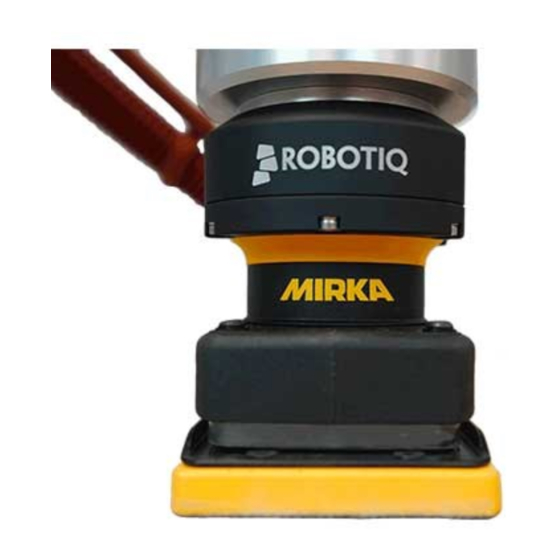
3.3.1. Mounting the Mirka finishing tool on e-Series robots 1. Mount the Robotiq Mirka bracket on the robot tool flange and secure it with the M6 screws and the tooth lock washers. 2. Align the Mirka finishing tool on the bracket. - Page 15 3.3.2. Mounting the Dynabrade finishing tool on e-Series robots 1. Mount the Robotiq Dynabrade bracket on the robot tool flange and secure it with the M6 screws and the tooth lock washers. 2. Align the Dynabrade finishing tool on the bracket.
- Page 16 3.3.3. Mounting the Finishing Kits on CB-Series robot The installation of Finishing kits on a CB-Series robot requires the preliminary installation of a Robotiq FT 300-S Force Torque Sensor. The steps below describe the installation procedure of the Sensor and the kits.
- Page 17 5. Secure by inserting the M4 screws and the Belleville washers (with the convex side upward) in a cross pattern to properly compress the O-ring. 6. Insert the dowel pin into hole #1 of the Force Torque Sensor and mount the Robotiq Mirka bracket on the FT 300-S Sensor. Secure it with the M6 screws and the tooth lock washers.
- Page 18 5. Secure by inserting the M4 screws and the Belleville washers (with the convex side upward) in a cross pattern to properly compress the O-ring. 6. Insert the dowel pin into hole #1 of the Force Torque Sensor and align the Robotiq Dynabrade bracket on the FT 300-S Sensor. Secure it with the M6 screws and the tooth lock washers.
- Page 19 Fig. 3-4: Mechanical installation of the Finishing Kit with the Dynabrade finishing tool on CB-Series robot 3.3.4. Supplying air to the valve 1. Push the 3/8 inch air tube into the finishing tool air inlet fitting. 2. Connect your air supply line to port #1. 3.
- Page 20 Maximum output voltage tolerance is 10%, exceeding this limit, 26.4 V DC could damage the Sensor. Info Robotiq recommends the use of the following power supply: TDK-Lambda DPP Series, 15W Single Output DIN Rail Mount Power Supply, DPP15-24. Wiring the FT 300-S Force Torque Sensor Power and communications are established with the FT 300-S Force Torque Sensor via a single device cable.
- Page 21 Kits along all axes without pulling out the connectors. Always protect the controller side of the cable connection with a strain relief cable clamp. Fig. 3-6: Pinout of the Robotiq Force Torque Sensor FT 300-S and color code for the respective cable type. Info Power pins 2 &...
-
Page 22: Urcap Package On Universal Robots
3.4. URCap Package on Universal Robots 3.4.1. On e-Series Robots Robotiq provides you with a Universal Robots URCap package that enables direct serial communication to your UR controller. Info To get the URCap package for your UR controller, browse to www.support.robotiq.com. - Page 23 Tap System in the navigation pane on the left. Select the URCap Tap the Plus (+) button to display the storage devices and browse for the URCap files. Once the file is selected, tap the Open button. Tap the Restart button to complete the URCap install- ation.By doing so, you accept the License agreement detailed in the URCap information textbox.
- Page 24 Select System in the navigation pane on the left. Select URCaps. In the Active URCaps box, select the URCap to unin- stall. Tap the minus (-) button to uninstall the URCap. Restart PolyScope to complete the uninstallation pro- cess. Robotiq Finishing Kits- Instruction Manual...
- Page 25 Force Copilot URCap pack- age. Go to www.support.robotiq.com, select Browse by product, click on your Robotiq product page and then Universal Robots Click on Software → Surface Finishing Kit software → Copilot, download the URCap zip and extract it on the root of a blank USB stick.
- Page 26 Restart PolyScope to complete the URCap install- ation.By doing so, you accept the License Agree- ment that is detailed in the URCap Information text When PolyScope reopens, the ActiveDrive toolbar will appear on the screen. Robotiq Finishing Kits- Instruction Manual...
- Page 27 URCap package uninstallation Go to Setup Robot. Tap URCaps Setup. In the Active URCaps box, select the URCap to unin- stall. Tap the minus (-) button to uninstall the URCap. Restart PolyScope to complete the uninstallation pro- cess.
-
Page 28: Software
Find Contact Offset Apply Contact Offset Path Generator Multipoint Path Multipoint Path (with External TCP option) Path Path (with External TCP option) Zero FT Sensor Active Drive Table 4-1: Nodes and Features, based on License Type Robotiq Finishing Kits- Instruction Manual... -
Page 29: Visible Nodes Using Copilot
4.2. Visible Nodes using Copilot Copilot gives the possibility to remove Copilot nodes from the menus in case they are not to be displayed. To do so, go to Installation > URCaps > Copilot, select the Visible Nodes tab and select the nodes to display. The system must be restarted to apply any change. - Page 30 Fig. 4-4: The Find Surface programing node is now part of the URCaps drop-down menu (UR CB-Series robot). Info An existing robot program containing nodes that are not currently displayed will still be executed without any issue. Info The Visible Nodes option only applies to the Copilot programing nodes. Robotiq Finishing Kits- Instruction Manual...
-
Page 31: Force And Torque Script Functions
4.3. Force and torque script functions Force Torque Sensor functions are made available in the Script drop-down menu. The rq_zero_sensor() function can be called at any point in a robot program to zero the force and torque values of the Force Torque Sensor. - Page 32 Features Primary icon Functionality Description name ActiveDrive Tap to toggle between the expanded and collapsed ActiveDrive Toolbar. When greyed out, the functionality is not available. Tap the button to see why it is not available. Robotiq Finishing Kits- Instruction Manual...
- Page 33 Primary icon Functionality Description name Tap to start or stop ActiveDrive. ActiveDrive will automatically turn off after 30s of inactivity. Start / Stop When started, ActiveDrive allows you to move the robot freely by applying forces on robot’s end-effector. This is different from the Free Drive feature on the robot, where you can move the robot arm.
- Page 34 If no external forces are applied, tap Zero Sensor. Message: Solution: The robot is not initialized: Tap OK and go to PolyScope’s home page. Tap Setup Robot and go to Initialize Robot to start the robot. Robotiq Finishing Kits- Instruction Manual...
- Page 35 Message: Solution: A program is already running: The ActiveDrive Toolbar cannot be used while a program is running. Stop the program to enable the ActiveDrive feature.
-
Page 36: Find Contact Offset Node
1. Go to the Installation tab → Features → Point. 2. Create a Feature Point, then tap "Set Point". Caution The feature point can be located anywhere, as long as the set coordinates remain within the robot reach at all times. On CB-Series robot: Robotiq Finishing Kits- Instruction Manual... - Page 37 3. Insert a Find Contact Offset node. 4. Tap Teach sequence. 5. From the " Feature to offset " drop- down list, select the feature point you previously created. For more information, select the help button. 6. Select Add translation or Add orientation to determine by how much the feature has been offset.
- Page 38 Fig. 4-6: Select this button to insert a Translation node. Fig. 4-7: Translation node Fig. 4-8: Add Translation program tree Follow these steps to setup a Translation node. 1. Select the Touch node from the program tree for detailed instructions. Robotiq Finishing Kits- Instruction Manual...
- Page 39 2. Tap Transition_Point from the Robot Program, move the robot to the required position, and select Set waypoint . Info Transition Point : feature point used to move between waypoints without colliding with the object. 3. Repeat for Approach_Point . 4.
- Page 40 The offset value is stored under the Universal Robots Installation tab. As such, this value can be reused either in the same robot program where it was first calculated, or in a different robot program altogether. 4.5.2. Add orientation Fig. 4-9: Select this button to insert an Orientation node. Fig. 4-10: Orientation node Robotiq Finishing Kits- Instruction Manual...
- Page 41 Fig. 4-11: Add Orientation program tree. The Orientation node can be set up in the same way as a Translation node. However, the Orientation node contains two Touch nodes. Configure each node as described in Add Translation section. The two offset values will be used to calculate a rotation angle.
-
Page 42: Apply Contact Offset Node
Reduce cycle time by inserting a Find Contact Offset node in the "Before_Start" section of the robot program, or as a sub-program. This strategy will reduce the frequency at which nodes are run in the course of your robot program. Robotiq Finishing Kits- Instruction Manual... -
Page 43: Finishing Tool Control Node
4.7. Finishing Tool Control node When running a program that uses a Robotiq end-effector, you can send a command to either start or stop this tool. The Finishing Tool Control node offers two commands: Start tool and Stop tool. Select Start tool to turn on your tool when it comes into contact with the surface. Select Stop tool to turn off your tool, after it is no longer in contact with the surface. - Page 44 You can enable e-stops, p-stops and program stops with options from the following window. Select the input and output ports to which your tool is wired, then make sure to select Low when not running from the dropdown list. Other settings will not enforce stops. Robotiq Finishing Kits- Instruction Manual...
-
Page 45: Path Recording Node
4.8. Path Recording node The Finishing Copilot software package adds a Path feature in PolyScope which can be used to record paths directly by moving the robot. The ActiveDrive Toolbar is a great tool to use while recording a path, as it is an easy way to hand guide the robot end effector. - Page 46 Actual pose of the robot or go configure a Feature point in Installation tab → Features → Point. When the External Tooling is selected: Configure the position and the orientation of your Tool Center Point (TCP) in Installation tab → Features → Point Robotiq Finishing Kits- Instruction Manual...
- Page 47 Overview Path recording and visualization. Path speed box. Path options. Warning section. Displayed whenever a setting results in a duration different than the original path duration. 4.8.1. Features* Primary icon Description Starts and stops the path recording.
- Page 48 If you tap the record button when a path is already recorded in a node, a warning pop-up will ask if you want to overwrite the path (tap OK) or keep the previously recorded path (tap Cancel). Robotiq Finishing Kits- Instruction Manual...
-
Page 49: Multipoint Path Node
Try inserting a Multipoint Path node in a Robotiq Force Control node. The former will perform the movements that were taught while taking into consideration the parameters set in the latter. - Page 50 If the External Tooling option is selected, you will have to create a feature point in Installation tab → Features → Point. Fig. 4-14: Multipoint Path node External tooling option Info Please note that a Multipoint Path parent node is always followed by a MoveJ command leading to the starting waypoint of the path sequence. Robotiq Finishing Kits- Instruction Manual...
- Page 51 4.9.1. How to set up a Multipoint Path Step 1 Select the MoveJ To waypoint child node in the program tree. A menu will display in the Command tab. Using the Freedrive mode or the UR Move menu, move the robot arm to the position you want to be the starting point of your Multipoint Path.
- Page 52 Adding several waypoints (lines or curves) without moving the robot in between them will result in the generation of identical waypoints. In order to remedy this situation, the user can edit each waypoint created and adjust its position. Robotiq Finishing Kits- Instruction Manual...
-
Page 53: Path Generator Node
You can toggle at any time between the Line to waypoint and Curve to waypoint options. Select the waypoint in the program tree and tap the appropriate radio button in the Command tab. Repeat step 2 until you complete your Multipoint Path. Fig. - Page 54 Vertical passes. You can also check the Path relative to a feature box to choose between the Actual pose of the robot or go configure a Feature point in Installation tab → Features → Point. Robotiq Finishing Kits- Instruction Manual...
- Page 55 Surface 1. If you have selected the Surface only or Peri- meter and Surface options, you have to con- figure the Surface tab. 2. The Tool Speed (A) and the Spacing (B) are respectively preseted at 60 mm/s and 30 mm but you can set your own parameters in function of your objectives.
- Page 56 You can also create UR variables: Program > Advanced > Assignment. To optimize your configuration, start your teach with the biggest part so you can minimize the errors when an adjustment of the dimensions is necessary. Robotiq Finishing Kits- Instruction Manual...
- Page 57 Margins A Margin is the distance between the runtime fin- ishing tool center and the taught Point 1, 2, 3 or 4. You can configure the four (4) margins by either: 1. Enter a value manually according to the desired results. 2.
- Page 58 To finish complex shapes, it is possible to put one path generator node after the other. If the first one’s end point is the second one’s starting point, both paths will be followed by the robot without interruption. Robotiq Finishing Kits- Instruction Manual...
- Page 59 6-Point Path 1. Define the six points that represent your surface. 2. Each point has its own node. 3. Choose Set Waypoint to define your waypoint (bring the robot to where your corner is). 4. Make sure the point you are teaching fits the point sequence on the illustration.
- Page 60 Note : this will make your robot move, make sure its workspace is clear. You can decide if you want to do vertical or horizontal passes. The illustration will show you the one you selected. Robotiq Finishing Kits- Instruction Manual...
-
Page 61: Insertion Nodes
4.11. Insertion nodes The Copilot software Package includes Insertion nodes, which can be used to perform spiral, rotational and linear movements to insert objects in holes or bores, or to make contact with a surface. It is an essential integration resource for streamlining robot programs in the framework of precise assembly applications. - Page 62 Force initiating insertion parameter: Textbox for the user to enter a force drop value indicating that the part/tool has found the path of least resistance, prior to completing the insertion process Robotiq Finishing Kits- Instruction Manual...
- Page 63 Radius increment per turn parameter: Textbox for the user to enter the distance between each spiral turn on the spiral radius Enable peck mode box: Box that enables the retraction of the tool between points of contact Maximum radius (Error condition): Textbox for the user to enter the maximum radius of the spiral, considering that no path of least resistance has been found Default values and units of measurement Parameter...
- Page 64 Default values and units of measurement Parameter Unit of measurement Default value Reference frame (Direction) Tool Axis (Direction) Linear speed mm/s Force initiating rotation Rotation speed °/s Maximum torque Maximum rotation angle (Error condition) ° Robotiq Finishing Kits- Instruction Manual...
-
Page 65: Find Surface Node
Features (Linear) Reference frame dropdown menu (Direction): Menu used to select the frame according to which the tool will move in space Axis dropdown menu (Direction): Menu used to select the direction in which the tool will go to reach the destination Advanced parameters box: Box that expands the advanced parameters menu when ticked Speed parameter: Textbox for the user to enter a speed value for the approach motion towards the destination Force threshold parameter: Textbox for the user to enter a force threshold value that completes the linear motion... - Page 66 Force threshold (Stop condition): Textbox for the user to enter a force threshold value that completes the linear motion Parameter Unit of measurement Default value Direction relative to the tool Motion speed mm/s Maximum distance traveled (Stop condition) Force threshold (Stop condition) Robotiq Finishing Kits- Instruction Manual...
- Page 67 Fig. 4-17: Find Surface node with stop condition(s)
-
Page 68: Force Control Node
Where a UR Move node would normally be used, the user shall record a Robotiq Path emulating the desired Move. In a situation where the user wants to make contact with a surface in accordance with the user-defined settings, a Wait instruction can be inserted as child of the Robotiq Force Control. - Page 69 Fig. 4-18: Force Control node with Reference Feature drop-down highlighted. Parameters Enable control: each checkbox corresponds to the enablement of force feeding along an axis (upper three options) or torque feeding around an axis (lower three options) Force/Torque: depending on which options were checked at step 1, the corresponding textboxes here should be filled with the desired force/torque values Force values applied are in newtons (N) –...
- Page 70 When entering into contact with a surface for the first time, the end-effector will pull back for it has reached the force/torque value entered at steps 2a and/or 2b. It will then go back to the surface and apply the same force/torque values while pulling back less and less over time. Robotiq Finishing Kits- Instruction Manual...
- Page 71 Fig. 4-20: End-effector experiencing adaptive stiffness upon repeated contact with a surface on CB-Series Current vs targeted position From the Force Control node, you can choose to either: Apply force at the current position Apply force based on a targeted position...
- Page 72 Fig. 4-21: Force control for e-Series Fig. 4-22: Force control for CB-Series Robotiq Finishing Kits- Instruction Manual...
- Page 73 Use the targeted position option when your defined trajectory is close to the actual part that will be processed within the Force Control node. Use the current position option when your defined trajectory may not resemble to the actual part that is being processed.
- Page 74 The Test button applies the user-defined settings of the Force Control node to the sensor, therefore moving along/around the corresponding axes, if the control had been enabled for the latter, regardless of other instructions entered before or after the Force Control node in the program tree. Robotiq Finishing Kits- Instruction Manual...
- Page 75 You can also test in real time your preset values by holding the Test button for the Tool and the Base features.
-
Page 76: Force Event Node
Click detection node. The program automatically goes to the following instructions. Indeed, a program instruction can be added if no click is detected. Robotiq Finishing Kits- Instruction Manual... - Page 77 To perform a click button action, as shown by the animated GIF, a Find Surface function has to be added up in the Click detection node. 4.14.2. Features (Wait for Force) The Wait for Force feature is used to detect a specific force or torque inside a Force Control node. The program waits until the force or torque is reached prior to the program continuation.
-
Page 78: Collision Detection Node
Sensor for CB- Series robot. Thus, any forces or torques applied to the robot arm will not be detected. Only those applied to the end-of-arm tooling are monitored. Robotiq Finishing Kits- Instruction Manual... - Page 79 The Collision Detection feature in the installation tab can be configured to start the monitoring upon every robot program start. On the other hand, the Collision Detection node in the Program tab starts a thread that runs in parallel with the rest of the robot program.
-
Page 80: Specifications
5. Specifications The following sections provide data on the various specifications of the Robotiq Force Torque Sensor. Section 5.1 details the technical dimensions of the Dynabrade and Mirka's brackets of the Finishing Kits. Section 5.2 details the technical dimensions of the sensor. - Page 81 Fig. 5-2: Technical dimensions of Dynabrade's bracket...
-
Page 82: Technical Dimensions Of The Ft 300-S Force Torque Sensor
5.2. Technical Dimensions of the FT 300-S Force Torque Sensor Fig. 5-3: Robotiq FT 300-S Sensor general technical dimensions. Robotiq Finishing Kits- Instruction Manual... -
Page 83: Mechanical Specifications
5.3. Mechanical Specifications 5.3.1. Mechanical Specifications of the Brackets for the Mirka and Dynabrade Sanders MIRKA DYNABRADE BRACKET BRACKET SPECIFICATION Metric Imperial Metric Imperial External envelope dimensions [77 89 37] mm [3.0 3.5 1.5] in. [100 119 31] mm [3.9 4.7 1.2] in. without sander Added height 7 mm... -
Page 84: Center Of Mass And Tool Center Point
Fx/300 + Fy/300 + Fz/300 + Mx/30 + My/30 + Mz/30 < 500% 5.4. Center of mass and tool center point Center of mass (mm) TCP (mm) Mass Product Finishing kit -7.0 60.0 138.0 1775 (SAND-FTS-S-CB-UR-KIT) Finishing kit (SAND-ES-UR-KIT) -9.0 37.0 100.0 1335 Robotiq Finishing Kits- Instruction Manual... -
Page 85: Signal Specifications
5.5. Signal Specifications FT 300 SPECIFICATION FT 300-S (prior to 10/2017) Force ±300 N Measuring range Torque ± 30 Nm Fx, Fy 1.2 N 0.1 N 0.5 N 0.1 N Signal noise Mx, My 0.02 Nm 0.005 Nm 0.03 Nm 0.003 Nm Fx, Fy Recommended threshold when mounted on a... -
Page 86: Electrical Ratings
5 to 24 V DC ± 10% Max power consumption Communication electrical interface RS-485 Recommended fuse Phoenix #0916604 (UT6-TMC M 1 A) Recommended power supply TDK-Lambda DPP Series 15W Single Output DIN Rail Mount Power Supply, DPP15-24 Robotiq Finishing Kits- Instruction Manual... -
Page 87: Maintenance
Correct functioning of your Sensor. Validity of your warranty. Proper lifetime for your Sensor. Warning Unless otherwise specified, any repairs done on the FT 300-S Force Torque Sensor will be done by Robotiq. 6.2.1. Maintenance Intervals Operation Daily Weekly... -
Page 88: Spare Parts, Kits And Accessories
1 x Sander & Mounting Kit Dynabrade (SAND-ROS-001) 1 x FT 300-S Sensor Kit for UR (FTS-300-S-UR-KIT) Sanding kit for UR CB-Series SAND-FTS-S-CB- 1 x Air Control accessories (ACC-AIR-001) UR-KIT 1 x Sander & Mounting Kit Dynabrade (SAND-ROS-001) Robotiq Finishing Kits- Instruction Manual... -
Page 89: Troubleshooting
8. Troubleshooting The following are some common troubleshooting hints, if you need further assistance please contact support@robotiq.com. 8.1. Monitoring the Sensor state (Surface Finishing and Sanding Kits) In order to view the sensor status and verify the force and torque values:... -
Page 90: Warranty
9.3. Exclusions Robotiq reserves the right to make changes in the design or construction of any of its products at any time without incurring an obligation to make any changes whatsoever on units already purchased. This warranty excludes failure resulting from: improper use or installation, normal wear and tear, accident, abuse, neglect, fire, water, lightning or other acts of nature, causes external to the product or other factors beyond Robotiq's control. -
Page 91: License Agreement
2.2 hereof including their modifications and upgrades and their related materials; 3. “Licensor” means Robotiq inc., a corporation incorporated under the laws of Quebec, having its registered office at 500-966 chemin Olivier, Lévis, Québec, Canada, G7A 2N1, which specializes into the conception, advanced man- ufacturing and sale of robotic products (the “Licensor’s Business”);... - Page 92 Software, which Software shall be used in accordance with such documentation. This documentation, if applic- able, will be provided, wholly or in part, within (i) this Agreement, (ii) the Licensor’s Web site http://robotiq.com/ (iii) the Licensor’s Products and the Purchase Agreement therewith, or (iv) any other agreement, document, support, whatsoever decided by the Licensor.
- Page 93 This Agreement shall be governed and construed in accordance with the laws of the province of Quebec and the federal laws of Canada applicable therein. Any legal action or proceeding between the Licensor and the End-User for any purpose concerning Robotiq Finishing Kits- Instruction Manual...
- Page 94 this Agreement or the parties' obligations hereunder shall be brought exclusively in a court of competent jurisdiction sitting in the judicial district of Québec, Québec. The Licensor’s failure to insist upon or enforce strict performance of any provision of this Agreement shall not be construed as a waiver of any provision or right.
-
Page 95: Contact
(01) 418-380-2788 Outside US and Canada Technical support and engineering option 3 Sales option 2 Head office Robotiq: 966, chemin Olivier Suite 500 St-Nicolas, Québec G7A 2N1 Canada Where automation Pros come to share their know-how and get answers. dof.robotiq.com Robotiq Finishing Kits- Instruction Manual...
Need help?
Do you have a question about the 56854B and is the answer not in the manual?
Questions and answers